EP0379197A2 - Pumpenlaufrad - Google Patents
Pumpenlaufrad Download PDFInfo
- Publication number
- EP0379197A2 EP0379197A2 EP90101018A EP90101018A EP0379197A2 EP 0379197 A2 EP0379197 A2 EP 0379197A2 EP 90101018 A EP90101018 A EP 90101018A EP 90101018 A EP90101018 A EP 90101018A EP 0379197 A2 EP0379197 A2 EP 0379197A2
- Authority
- EP
- European Patent Office
- Prior art keywords
- boss
- impeller
- main shroud
- retainer plate
- pump impeller
- Prior art date
- Legal status (The legal status is an assumption and is not a legal conclusion. Google has not performed a legal analysis and makes no representation as to the accuracy of the status listed.)
- Granted
Links
Images

Classifications
-
- F—MECHANICAL ENGINEERING; LIGHTING; HEATING; WEAPONS; BLASTING
- F04—POSITIVE - DISPLACEMENT MACHINES FOR LIQUIDS; PUMPS FOR LIQUIDS OR ELASTIC FLUIDS
- F04D—NON-POSITIVE-DISPLACEMENT PUMPS
- F04D29/00—Details, component parts, or accessories
- F04D29/18—Rotors
-
- F—MECHANICAL ENGINEERING; LIGHTING; HEATING; WEAPONS; BLASTING
- F04—POSITIVE - DISPLACEMENT MACHINES FOR LIQUIDS; PUMPS FOR LIQUIDS OR ELASTIC FLUIDS
- F04D—NON-POSITIVE-DISPLACEMENT PUMPS
- F04D29/00—Details, component parts, or accessories
- F04D29/18—Rotors
- F04D29/22—Rotors specially for centrifugal pumps
- F04D29/2205—Conventional flow pattern
- F04D29/2222—Construction and assembly
- F04D29/2227—Construction and assembly for special materials
-
- F—MECHANICAL ENGINEERING; LIGHTING; HEATING; WEAPONS; BLASTING
- F05—INDEXING SCHEMES RELATING TO ENGINES OR PUMPS IN VARIOUS SUBCLASSES OF CLASSES F01-F04
- F05D—INDEXING SCHEME FOR ASPECTS RELATING TO NON-POSITIVE-DISPLACEMENT MACHINES OR ENGINES, GAS-TURBINES OR JET-PROPULSION PLANTS
- F05D2230/00—Manufacture
- F05D2230/20—Manufacture essentially without removing material
- F05D2230/23—Manufacture essentially without removing material by permanently joining parts together
- F05D2230/232—Manufacture essentially without removing material by permanently joining parts together by welding
-
- F—MECHANICAL ENGINEERING; LIGHTING; HEATING; WEAPONS; BLASTING
- F05—INDEXING SCHEMES RELATING TO ENGINES OR PUMPS IN VARIOUS SUBCLASSES OF CLASSES F01-F04
- F05D—INDEXING SCHEME FOR ASPECTS RELATING TO NON-POSITIVE-DISPLACEMENT MACHINES OR ENGINES, GAS-TURBINES OR JET-PROPULSION PLANTS
- F05D2300/00—Materials; Properties thereof
- F05D2300/10—Metals, alloys or intermetallic compounds
- F05D2300/17—Alloys
- F05D2300/171—Steel alloys
-
- F—MECHANICAL ENGINEERING; LIGHTING; HEATING; WEAPONS; BLASTING
- F16—ENGINEERING ELEMENTS AND UNITS; GENERAL MEASURES FOR PRODUCING AND MAINTAINING EFFECTIVE FUNCTIONING OF MACHINES OR INSTALLATIONS; THERMAL INSULATION IN GENERAL
- F16B—DEVICES FOR FASTENING OR SECURING CONSTRUCTIONAL ELEMENTS OR MACHINE PARTS TOGETHER, e.g. NAILS, BOLTS, CIRCLIPS, CLAMPS, CLIPS OR WEDGES; JOINTS OR JOINTING
- F16B2200/00—Constructional details of connections not covered for in other groups of this subclass
- F16B2200/40—Clamping arrangements where clamping parts are received in recesses of elements to be connected
- F16B2200/403—Threaded clamping parts
-
- Y—GENERAL TAGGING OF NEW TECHNOLOGICAL DEVELOPMENTS; GENERAL TAGGING OF CROSS-SECTIONAL TECHNOLOGIES SPANNING OVER SEVERAL SECTIONS OF THE IPC; TECHNICAL SUBJECTS COVERED BY FORMER USPC CROSS-REFERENCE ART COLLECTIONS [XRACs] AND DIGESTS
- Y10—TECHNICAL SUBJECTS COVERED BY FORMER USPC
- Y10T—TECHNICAL SUBJECTS COVERED BY FORMER US CLASSIFICATION
- Y10T403/00—Joints and connections
- Y10T403/70—Interfitted members
- Y10T403/7098—Non-circular rod section is joint component
Definitions
- the present invention relates to a pump impeller manufactured by press forming of steel plate, which is advantageously used as an impeller of a centrifugal pump made of steel plate.
- Conventional pump impellers manufactured by press forming of steel plate are generally classified into two groups with respect their structure, namely, (a) two engaging planes type, and (b) boss welding type.
- Figs. 6(a) and 6(b) are a front view and a side sectional view, respectively, of a main portion of an impeller according to the two engaging planes type (a).
- a retainer plate 2 is fixed to the central portion of the impeller main shroud 1.
- the main shroud 1 and the retainer plate 2 are both formed with circular bores 3 having two parallel engaging planes for fitting to a main shaft (not shown) having the same cross-sectional shape, and connected with each other in an axial direction by means of screws.
- numeral 4 denotes a side plate
- numeral 5 an impeller blade.
- Figs. 7(a) and 7(b) are a front view and a side sectional view, respectively, of a main portion of an impeller according to the boss welding type (b).
- the same numerals as in Figs. 6(a) and 6(b) indicate the same or similar portions.
- a boss 6 is formed, through such as machining, with a slunt or conical surface 6a on the front side (suction side) of the impeller, a step portion 6b on the rear end of the conical surface 6a, and a cylindrical surface 6c of a smaller diameter adjacent to the step portion 6b.
- the impeller main shroud 1A is formed with a central aperture.
- the main shroud is fitted to the boss with its central aperture fitting on the cylindrical surface 6c and with its central portion abutting on the step portion 6b, and then the main shroud and the boss are connected with each other by welding 7 between the rear portion of the conical surface 6a and the abutting portion of the main shroud 1A.
- an object of this invention is to provide a pump impeller in which the welded portion of the impeller suffers no significant stress concentration and thereby makes the adoption of simple welding processes possible.
- Another object of this invention is to provide an impeller in which transmission of power from the boss to the impeller main shroud is effected through relatively large area and whereby stress concentration at the transmission area is avoided.
- Still another object of this invention is to provide an impeller in which the boss suffers no thermal deformation upon welding and no additional machining is required to the boss after welding.
- a further object of this invention is to provide an impeller in which no special cross-sectional shape is required of the impeller main shaft.
- the pump impeller comprises a boss formed with a polygonal portion on the periphery of the boss and with a bore at a central portion of the boss for connecting the boss with a main shaft, a main shroud formed with a polygonal recess for fitting to said polygonal portion, and a retainer plate mounted on an end position of the boss opposite to the end portion from which the main shroud is fitted to the boss and the retainer plate is connected with the main shroud by welding.
- the boss is formed with a radial step on said polygonal portion at the rear end thereof, that the main shroud is formed with a skirt portion radially inwardly extending from an end of said recess, and that the skirt portion is abutted on and engaged with the radial step.
- a radially inner portion of said retainer plate may be abut said radial step.
- the polygonal portion formed on the periphery of the boss is fitted to the polygonal recess of the impeller main shroud, and the retainer plate, which is mounted on the boss from the side opposite to the main shroud mounting side, is welded to the main shroud.
- the main shroud is surely secured to the boss, which is fixed, in turn, to the main shaft by means of such as a key way.
- the torque is transmitted from the main shaft to the boss through such as a key, and then, to the main shroud through the surfaces of the polygonal portion of the boss and the corresponding surfaces of the polygonal recess of the main shroud, thereby delivering the water from the impeller.
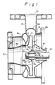
- Fig. 1 is a longitudinal sectional view of a centrifugal pump having an impeller made of steel plate according to an embodiment of the present invention.
- a boss 13 is provided for mounting an impeller main shroud 11 on a main shaft 12.
- the boss 13 is formed at its central (inner circumference side) portion with a bore 13a which is adapted to fit to the main shaft 12, and on a part of the bore with a key way 13b for power transmitting.
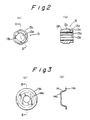
- the boss is further formed with a polygonal (hexagonal in the figure) portion 13c on the periphery of the boss at the axially middle portion of the same, the polygonal portion being adapted to fit to the impeller main shroud 11 as will be explained hereunder.
- the radial step 13d determines the axial position of the main shroud.
- a slant or conical surface 13f which is machined to have a tapered shape converging in the forward direction, and adapted to fit to a correspondingly shaped retainer plate 14.
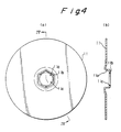
- a front end portion 14a of the retainer plate 14 (see Figs. 3(a) and 3(b)) is, upon assembling of an impeller, gripped between a nut 12a for the main shaft and the front surface of the boss 13, while a rear end portion 14b abut on the main shroud 11.
- the middle portion of the retainer plate has a tapered shape corresponding to the slant surface 13f of the boss 13. This tapered shape of the retainer plate allows smooth suction flow of the pumped water into the impeller and whereby increases pump performance.
- the impeller main shroud 11 is formed by press forming at its central portion with a polygonal (hexagonal in the figure) tubular recess 11a which has the same shape as that of the polygonal portion 13c formed on the periphery of the boss.
- a skirt portion 11b extending radially inwardly from an end of the recess 11a is formed with a circular aperture 11c for fitting to the cylindrical surface 13e of the boss 13, and said skirt portion abuts on the step 13d of the boss
- the polygonal portion 13c formed on the periphery of the boss and the polygonal recess 11a formed in the main shroud 11 fit to each other, and the step 13d formed on the periphery of the boss and the radially inwardly extending skirt portion 11b of the main shroud 11 abut on each other.
- the main shroud 11 is fitted to the boss 13.
- the retainer plate 14 is mounted on the boss from the side opposite to the main shroud fitting side, and the rear end or radially outer portion 14b of the retainer plate 14 is strongly secured to the main shroud 11 by a projection welding or a spot welding 15.
- numeral 16 denotes a casing body manufactured from a steel plate by press forming, numeral 16a a volute expanded portion, numeral 16b a casing flange, numeral 16c a casing front portion, numeral 16d a suction port portion, numeral 17 a nozzle connecting the maximum portion of the volute with a discharge port 20, numeral 18 a casing cover, and numeral 19 a suction port.
- the torque is transmitted from the main shaft 12 through the key and key way to the boss 13, and then to the main shroud 11 through the polygonal portion formed on the periphery of the boss and polygonal recess of the main shroud, thereby delivering out the water under the function of the impeller. Since the torque transmitted from the main shaft 12 to the boss 13 is further transmitted to the main shroud 11 as stated above, the transmission of the torque is conducted through polygonal surfaces. In consequence, no substantial stress concentration at the torque transmitting portion can occur, and no significant stress acting in a rotational direction is produced at the welding portion 15.
- the cross-section of the polygonal portion 13c formed on the periphery of the boss 13 is hexagonal, any polygonal shape other than hexagon will do.
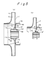
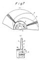
- Fig. 5(a) is a longitudinal sectional view of an impeller formed as a double-liner ring type one according to another embodiment of the present invention.
- the same numerals in the figure as in Fig. 1 denote the same members or portions.
- the direction of the recess 11a′ of the main shroud 11′ is the reverse in comparison with that in the embodiment shown in Fig. 1, and the radially inwardly extending skirt portion 11b′ abuts on the front end surface of the boss 13.
- a radially inner end portion 14a′ of the retainer plate 14′ engages with the step portion 13d of the boss 13, and a radially outer end portion 14b′ is axially extended to form a cylindrical portion, i.e. a liner ring 14c.
- the main shroud 11′ and the retainer plate 14′ are formed near their central portion with a plurality of holes (balance hole) 10, which functions to balance the pressure at region (B) radially inside of the liner ring 14c with that at the suction side region (A).
- Fig. 5(b) is further embodiment of an impeller for a double-liner ring type according to the invention.
- a main shroud 11 ⁇ and a retainer plate 14 ⁇ are similar to those shown in Fig. 1, but a separate liner ring 24 is provided on the rear surface of the impeller to form a double-liner ring type impeller.
Landscapes
- Engineering & Computer Science (AREA)
- Mechanical Engineering (AREA)
- General Engineering & Computer Science (AREA)
- Structures Of Non-Positive Displacement Pumps (AREA)
- Rotary Pumps (AREA)
- Saccharide Compounds (AREA)
- Applications Or Details Of Rotary Compressors (AREA)
Applications Claiming Priority (2)
| Application Number | Priority Date | Filing Date | Title |
|---|---|---|---|
| JP861989 | 1989-01-19 | ||
| JP8619/89 | 1989-01-19 |
Publications (3)
| Publication Number | Publication Date |
|---|---|
| EP0379197A2 true EP0379197A2 (de) | 1990-07-25 |
| EP0379197A3 EP0379197A3 (en) | 1990-09-26 |
| EP0379197B1 EP0379197B1 (de) | 1993-12-08 |
Family
ID=11697960
Family Applications (1)
| Application Number | Title | Priority Date | Filing Date |
|---|---|---|---|
| EP90101018A Expired - Lifetime EP0379197B1 (de) | 1989-01-19 | 1990-01-18 | Pumpenlaufrad |
Country Status (9)
| Country | Link |
|---|---|
| US (1) | US4986736A (de) |
| EP (1) | EP0379197B1 (de) |
| JP (1) | JPH02277998A (de) |
| KR (1) | KR970010513B1 (de) |
| AT (1) | ATE98341T1 (de) |
| DE (3) | DE69004975T2 (de) |
| DK (1) | DK0379197T3 (de) |
| ES (1) | ES2048868T3 (de) |
| IT (2) | IT1239538B (de) |
Cited By (2)
| Publication number | Priority date | Publication date | Assignee | Title |
|---|---|---|---|---|
| US10865802B2 (en) | 2018-05-09 | 2020-12-15 | Philip Wessels | Double-sided single impeller with dual intake pump |
| EP3889437B1 (de) * | 2020-03-31 | 2025-08-13 | Pedrollo S.p.a. | Kreiselpumpenlaufrad |
Families Citing this family (44)
| Publication number | Priority date | Publication date | Assignee | Title |
|---|---|---|---|---|
| JP2809487B2 (ja) * | 1989-07-05 | 1998-10-08 | 株式会社荏原製作所 | 遠心ポンプケーシング |
| DE4131088A1 (de) * | 1991-09-18 | 1993-03-25 | Siemens Ag | Verfahren und einrichtung zum messen der konzentration eines gases im rauchgas |
| JPH0968195A (ja) * | 1995-08-31 | 1997-03-11 | Ebara Corp | キャンドモータポンプ |
| US20050013715A1 (en) * | 2003-07-14 | 2005-01-20 | Cooper Paul V. | System for releasing gas into molten metal |
| US20070253807A1 (en) | 2006-04-28 | 2007-11-01 | Cooper Paul V | Gas-transfer foot |
| US7470392B2 (en) * | 2003-07-14 | 2008-12-30 | Cooper Paul V | Molten metal pump components |
| US7402276B2 (en) | 2003-07-14 | 2008-07-22 | Cooper Paul V | Pump with rotating inlet |
| CN1675016A (zh) * | 2002-08-02 | 2005-09-28 | Abb涡轮系统有限公司 | 夹紧旋转对称物体的方法和装置及所要夹紧物体的结构 |
| US7906068B2 (en) * | 2003-07-14 | 2011-03-15 | Cooper Paul V | Support post system for molten metal pump |
| US9205490B2 (en) | 2007-06-21 | 2015-12-08 | Molten Metal Equipment Innovations, Llc | Transfer well system and method for making same |
| US8337746B2 (en) * | 2007-06-21 | 2012-12-25 | Cooper Paul V | Transferring molten metal from one structure to another |
| US9409232B2 (en) | 2007-06-21 | 2016-08-09 | Molten Metal Equipment Innovations, Llc | Molten metal transfer vessel and method of construction |
| US9643247B2 (en) | 2007-06-21 | 2017-05-09 | Molten Metal Equipment Innovations, Llc | Molten metal transfer and degassing system |
| US8613884B2 (en) | 2007-06-21 | 2013-12-24 | Paul V. Cooper | Launder transfer insert and system |
| US9410744B2 (en) | 2010-05-12 | 2016-08-09 | Molten Metal Equipment Innovations, Llc | Vessel transfer insert and system |
| US8366993B2 (en) * | 2007-06-21 | 2013-02-05 | Cooper Paul V | System and method for degassing molten metal |
| US9156087B2 (en) | 2007-06-21 | 2015-10-13 | Molten Metal Equipment Innovations, Llc | Molten metal transfer system and rotor |
| US8449814B2 (en) * | 2009-08-07 | 2013-05-28 | Paul V. Cooper | Systems and methods for melting scrap metal |
| US8535603B2 (en) * | 2009-08-07 | 2013-09-17 | Paul V. Cooper | Rotary degasser and rotor therefor |
| US8444911B2 (en) | 2009-08-07 | 2013-05-21 | Paul V. Cooper | Shaft and post tensioning device |
| US10428821B2 (en) * | 2009-08-07 | 2019-10-01 | Molten Metal Equipment Innovations, Llc | Quick submergence molten metal pump |
| US8524146B2 (en) | 2009-08-07 | 2013-09-03 | Paul V. Cooper | Rotary degassers and components therefor |
| US8714914B2 (en) | 2009-09-08 | 2014-05-06 | Paul V. Cooper | Molten metal pump filter |
| US9108244B2 (en) * | 2009-09-09 | 2015-08-18 | Paul V. Cooper | Immersion heater for molten metal |
| US8807918B2 (en) * | 2010-06-18 | 2014-08-19 | Hamilton Sundstrand Corporation | Rotating catcher for impeller containment |
| JP5606358B2 (ja) | 2011-02-24 | 2014-10-15 | 三菱重工業株式会社 | インペラ及びこれを備えたロータ並びにインペラの製造方法 |
| JP2013047479A (ja) | 2011-08-29 | 2013-03-07 | Mitsubishi Heavy Ind Ltd | インペラ及びこれを備えた回転機械並びにインペラの製造方法 |
| CN103122871A (zh) * | 2011-11-18 | 2013-05-29 | 镇江江大泵业科技有限公司 | 叶轮螺母防反转松脱技术 |
| JP5907723B2 (ja) * | 2011-12-26 | 2016-04-26 | 三菱重工業株式会社 | 回転機械の製造方法 |
| US9903383B2 (en) | 2013-03-13 | 2018-02-27 | Molten Metal Equipment Innovations, Llc | Molten metal rotor with hardened top |
| US9011761B2 (en) | 2013-03-14 | 2015-04-21 | Paul V. Cooper | Ladle with transfer conduit |
| US10052688B2 (en) | 2013-03-15 | 2018-08-21 | Molten Metal Equipment Innovations, Llc | Transfer pump launder system |
| US10138892B2 (en) | 2014-07-02 | 2018-11-27 | Molten Metal Equipment Innovations, Llc | Rotor and rotor shaft for molten metal |
| CN106795891B (zh) * | 2014-10-14 | 2020-11-10 | 株式会社荏原制作所 | 离心泵用的叶轮组件 |
| US10947980B2 (en) | 2015-02-02 | 2021-03-16 | Molten Metal Equipment Innovations, Llc | Molten metal rotor with hardened blade tips |
| TWI725016B (zh) * | 2015-03-20 | 2021-04-21 | 日商荏原製作所股份有限公司 | 用於離心式泵浦之葉輪 |
| US10267314B2 (en) | 2016-01-13 | 2019-04-23 | Molten Metal Equipment Innovations, Llc | Tensioned support shaft and other molten metal devices |
| US11149747B2 (en) | 2017-11-17 | 2021-10-19 | Molten Metal Equipment Innovations, Llc | Tensioned support post and other molten metal devices |
| KR102125868B1 (ko) * | 2018-10-15 | 2020-06-23 | 주식회사 코아비스 | 전동식 워터펌프용 임펠러 |
| JP7292858B2 (ja) * | 2018-11-15 | 2023-06-19 | 株式会社荏原製作所 | 羽根車、該羽根車を備えたポンプ、および該羽根車の製造方法 |
| US11858036B2 (en) | 2019-05-17 | 2024-01-02 | Molten Metal Equipment Innovations, Llc | System and method to feed mold with molten metal |
| US11873845B2 (en) | 2021-05-28 | 2024-01-16 | Molten Metal Equipment Innovations, Llc | Molten metal transfer device |
| CN114321001B (zh) * | 2022-03-15 | 2022-06-10 | 四川川工泵业有限公司 | 一种旋喷泵用的叶轮 |
| US12146508B2 (en) | 2022-05-26 | 2024-11-19 | Molten Metal Equipment Innovations, Llc | Axial pump and riser |
Family Cites Families (18)
| Publication number | Priority date | Publication date | Assignee | Title |
|---|---|---|---|---|
| DE462853C (de) * | 1927-11-05 | 1928-07-19 | Lorenzen G M B H C | Laeufer fuer Kreiselverdichter, dessen Deckscheibe gegen die freien Kanten der mit der Laeuferscheibe aus einem Stueck gearbeiteten Schaufeln in axialer Richtung gepresstwird |
| US3019039A (en) * | 1956-04-09 | 1962-01-30 | Fairchild Stratos Corp | Means for mounting a body on a rotating shaft |
| US3213794A (en) * | 1962-02-02 | 1965-10-26 | Nash Engineering Co | Centrifugal pump with gas separation means |
| DE2303608B2 (de) * | 1973-01-25 | 1981-02-12 | Grundfos A/S, Bjerringbro (Daenemark) | Wellenlagerung, insbesondere für eine Kreiselpumpe |
| US4080079A (en) * | 1977-01-06 | 1978-03-21 | Visi-Trol Engineering Company | Universal joint |
| US4285305A (en) * | 1979-11-16 | 1981-08-25 | Tecumseh Products Company | Keyed adapter sleeve |
| US4337747A (en) * | 1980-02-08 | 1982-07-06 | Lucas Industries Limited | Fuel injection pumping apparatus |
| JPS5752397A (en) * | 1980-08-08 | 1982-03-27 | Brother Ind Ltd | Stop control system of pulse motor |
| JPS5892497U (ja) * | 1981-12-16 | 1983-06-22 | 株式会社日立製作所 | ポンプの鋼板製羽根車 |
| JPS58144697A (ja) * | 1982-02-22 | 1983-08-29 | Hitachi Ltd | 鋼板製ポンプ羽根車 |
| JPS61123701A (ja) * | 1984-11-21 | 1986-06-11 | Toyota Motor Corp | セラミツクス製タ−ビンロ−タ |
| DE3517499A1 (de) * | 1985-05-15 | 1986-11-20 | Klein, Schanzlin & Becker Ag, 6710 Frankenthal | Laufrad |
| FR2586987B1 (fr) * | 1985-09-06 | 1990-06-01 | Peugeot Cycles | Sous-ensemble telescopique pour colonne de direction |
| JPH0247279Y2 (de) * | 1986-01-08 | 1990-12-12 | ||
| US4720242A (en) * | 1987-03-23 | 1988-01-19 | Lowara, S.P.A. | Centrifugal pump impeller |
| JPS63259194A (ja) * | 1987-04-15 | 1988-10-26 | Hitachi Ltd | 鋼板製羽根車 |
| US4925369A (en) * | 1987-10-28 | 1990-05-15 | Brunswick Corporation | Easily removed marine propeller |
| US4890980A (en) * | 1988-08-08 | 1990-01-02 | Ingersoll-Rand Company | Centrifugal pump |
-
1990
- 1990-01-18 ES ES90101018T patent/ES2048868T3/es not_active Expired - Lifetime
- 1990-01-18 DE DE69004975T patent/DE69004975T2/de not_active Expired - Fee Related
- 1990-01-18 DE DE4001379A patent/DE4001379C2/de not_active Expired - Fee Related
- 1990-01-18 JP JP2007031A patent/JPH02277998A/ja active Pending
- 1990-01-18 DE DE9000532U patent/DE9000532U1/de not_active Expired - Lifetime
- 1990-01-18 AT AT90101018T patent/ATE98341T1/de not_active IP Right Cessation
- 1990-01-18 DK DK90101018.1T patent/DK0379197T3/da active
- 1990-01-18 EP EP90101018A patent/EP0379197B1/de not_active Expired - Lifetime
- 1990-01-18 US US07/466,845 patent/US4986736A/en not_active Expired - Lifetime
- 1990-01-19 KR KR1019900000618A patent/KR970010513B1/ko not_active Expired - Fee Related
- 1990-01-19 IT IT67034A patent/IT1239538B/it active IP Right Grant
- 1990-01-19 IT IT05282990U patent/IT223986Z2/it active IP Right Grant
Cited By (2)
| Publication number | Priority date | Publication date | Assignee | Title |
|---|---|---|---|---|
| US10865802B2 (en) | 2018-05-09 | 2020-12-15 | Philip Wessels | Double-sided single impeller with dual intake pump |
| EP3889437B1 (de) * | 2020-03-31 | 2025-08-13 | Pedrollo S.p.a. | Kreiselpumpenlaufrad |
Also Published As
| Publication number | Publication date |
|---|---|
| IT9052829U1 (it) | 1990-07-20 |
| EP0379197B1 (de) | 1993-12-08 |
| DE4001379C2 (de) | 2003-05-15 |
| DE4001379A1 (de) | 1990-07-26 |
| IT9052829V0 (it) | 1990-01-19 |
| EP0379197A3 (en) | 1990-09-26 |
| IT9067034A1 (it) | 1991-07-19 |
| DK0379197T3 (da) | 1994-04-11 |
| DE69004975D1 (de) | 1994-01-20 |
| DE9000532U1 (de) | 1990-04-19 |
| ES2048868T3 (es) | 1994-04-01 |
| DE69004975T2 (de) | 1994-06-09 |
| ATE98341T1 (de) | 1993-12-15 |
| US4986736A (en) | 1991-01-22 |
| KR900011995A (ko) | 1990-08-02 |
| JPH02277998A (ja) | 1990-11-14 |
| IT9067034A0 (it) | 1990-01-19 |
| IT223986Z2 (it) | 1995-10-05 |
| IT1239538B (it) | 1993-11-05 |
| KR970010513B1 (ko) | 1997-06-26 |
Similar Documents
| Publication | Publication Date | Title |
|---|---|---|
| EP0379197B1 (de) | Pumpenlaufrad | |
| US5256033A (en) | Sheet metal interstage casing for a pump | |
| US5344285A (en) | Centrifugal pump with monolithic diffuser and return vane channel ring member | |
| US5961246A (en) | Structure for joining impeller to rotatable shaft | |
| US4639188A (en) | Turbine wheel containment | |
| US5310310A (en) | Pump casing made of sheet metal | |
| US6250881B1 (en) | Molten metal shaft and impeller bearing assembly | |
| US5176497A (en) | Boreless hub compressor wheel assembly for a turbocharger | |
| GB1579143A (en) | Impeller for a fluid flow machine | |
| US4610600A (en) | Adjustable-pitch axial fan wheel | |
| US6030051A (en) | Two-piece steel wheel | |
| US3070348A (en) | Composite rotor | |
| US4863353A (en) | Attaching arrangement | |
| US4453889A (en) | Stacked rotor | |
| US4795311A (en) | Centrifugal compressor impeller | |
| US20040253134A1 (en) | Vane pump with integrated shaft, rotor and disc | |
| US7905024B2 (en) | Drive wheel | |
| EP0934465B1 (de) | Rotor mit wellenlagern | |
| EP1114947B1 (de) | Baueinheit aus einer einwegkupplung und einem lager | |
| EP1061233B1 (de) | Gasturbinenrotorverbindung | |
| JPH03141898A (ja) | 遠心型圧縮機の翼車 | |
| EP0129311B1 (de) | Aufbau eines Verdichterlaufrades | |
| US6059486A (en) | Flat key washer | |
| JPS5944000A (ja) | 循環ポンプに使用されるヘツド・ケ−シング | |
| JPS61190191A (ja) | 車両用電動式燃料ポンプ |
Legal Events
| Date | Code | Title | Description |
|---|---|---|---|
| PUAI | Public reference made under article 153(3) epc to a published international application that has entered the european phase |
Free format text: ORIGINAL CODE: 0009012 |
|
| AK | Designated contracting states |
Kind code of ref document: A2 Designated state(s): AT BE CH DE DK ES FR GB GR IT LI LU NL SE |
|
| PUAL | Search report despatched |
Free format text: ORIGINAL CODE: 0009013 |
|
| AK | Designated contracting states |
Kind code of ref document: A3 Designated state(s): AT BE CH DE DK ES FR GB GR IT LI LU NL |
|
| 17P | Request for examination filed |
Effective date: 19910102 |
|
| 17Q | First examination report despatched |
Effective date: 19920408 |
|
| ITF | It: translation for a ep patent filed | ||
| GRAA | (expected) grant |
Free format text: ORIGINAL CODE: 0009210 |
|
| AK | Designated contracting states |
Kind code of ref document: B1 Designated state(s): AT BE CH DE DK ES FR GB GR IT LI LU NL SE |
|
| PG25 | Lapsed in a contracting state [announced via postgrant information from national office to epo] |
Ref country code: GR Free format text: LAPSE BECAUSE OF FAILURE TO SUBMIT A TRANSLATION OF THE DESCRIPTION OR TO PAY THE FEE WITHIN THE PRESCRIBED TIME-LIMIT Effective date: 19931208 Ref country code: BE Effective date: 19931208 |
|
| REF | Corresponds to: |
Ref document number: 98341 Country of ref document: AT Date of ref document: 19931215 Kind code of ref document: T |
|
| REF | Corresponds to: |
Ref document number: 69004975 Country of ref document: DE Date of ref document: 19940120 |
|
| ET | Fr: translation filed | ||
| PG25 | Lapsed in a contracting state [announced via postgrant information from national office to epo] |
Ref country code: LU Free format text: LAPSE BECAUSE OF NON-PAYMENT OF DUE FEES Effective date: 19940131 |
|
| REG | Reference to a national code |
Ref country code: ES Ref legal event code: FG2A Ref document number: 2048868 Country of ref document: ES Kind code of ref document: T3 |
|
| REG | Reference to a national code |
Ref country code: DK Ref legal event code: T3 |
|
| PLBE | No opposition filed within time limit |
Free format text: ORIGINAL CODE: 0009261 |
|
| STAA | Information on the status of an ep patent application or granted ep patent |
Free format text: STATUS: NO OPPOSITION FILED WITHIN TIME LIMIT |
|
| 26N | No opposition filed | ||
| EAL | Se: european patent in force in sweden |
Ref document number: 90101018.1 |
|
| REG | Reference to a national code |
Ref country code: GB Ref legal event code: IF02 |
|
| PGFP | Annual fee paid to national office [announced via postgrant information from national office to epo] |
Ref country code: ES Payment date: 20050211 Year of fee payment: 16 |
|
| PGFP | Annual fee paid to national office [announced via postgrant information from national office to epo] |
Ref country code: SE Payment date: 20060105 Year of fee payment: 17 |
|
| PGFP | Annual fee paid to national office [announced via postgrant information from national office to epo] |
Ref country code: FR Payment date: 20060110 Year of fee payment: 17 |
|
| PGFP | Annual fee paid to national office [announced via postgrant information from national office to epo] |
Ref country code: AT Payment date: 20060111 Year of fee payment: 17 |
|
| PGFP | Annual fee paid to national office [announced via postgrant information from national office to epo] |
Ref country code: DE Payment date: 20060112 Year of fee payment: 17 |
|
| PGFP | Annual fee paid to national office [announced via postgrant information from national office to epo] |
Ref country code: CH Payment date: 20060113 Year of fee payment: 17 |
|
| PGFP | Annual fee paid to national office [announced via postgrant information from national office to epo] |
Ref country code: NL Payment date: 20060115 Year of fee payment: 17 |
|
| PGFP | Annual fee paid to national office [announced via postgrant information from national office to epo] |
Ref country code: GB Payment date: 20060118 Year of fee payment: 17 Ref country code: DK Payment date: 20060118 Year of fee payment: 17 |
|
| PGFP | Annual fee paid to national office [announced via postgrant information from national office to epo] |
Ref country code: IT Payment date: 20060131 Year of fee payment: 17 |
|
| PG25 | Lapsed in a contracting state [announced via postgrant information from national office to epo] |
Ref country code: SE Free format text: LAPSE BECAUSE OF NON-PAYMENT OF DUE FEES Effective date: 20070119 |
|
| PG25 | Lapsed in a contracting state [announced via postgrant information from national office to epo] |
Ref country code: LI Free format text: LAPSE BECAUSE OF NON-PAYMENT OF DUE FEES Effective date: 20070131 Ref country code: CH Free format text: LAPSE BECAUSE OF NON-PAYMENT OF DUE FEES Effective date: 20070131 |
|
| PG25 | Lapsed in a contracting state [announced via postgrant information from national office to epo] |
Ref country code: DE Free format text: LAPSE BECAUSE OF NON-PAYMENT OF DUE FEES Effective date: 20070801 |
|
| REG | Reference to a national code |
Ref country code: CH Ref legal event code: PL |
|
| EUG | Se: european patent has lapsed | ||
| GBPC | Gb: european patent ceased through non-payment of renewal fee |
Effective date: 20070118 |
|
| NLV4 | Nl: lapsed or anulled due to non-payment of the annual fee |
Effective date: 20070801 |
|
| REG | Reference to a national code |
Ref country code: DK Ref legal event code: EBP |
|
| REG | Reference to a national code |
Ref country code: FR Ref legal event code: ST Effective date: 20070930 |
|
| PG25 | Lapsed in a contracting state [announced via postgrant information from national office to epo] |
Ref country code: GB Free format text: LAPSE BECAUSE OF NON-PAYMENT OF DUE FEES Effective date: 20070118 Ref country code: AT Free format text: LAPSE BECAUSE OF NON-PAYMENT OF DUE FEES Effective date: 20070118 |
|
| PG25 | Lapsed in a contracting state [announced via postgrant information from national office to epo] |
Ref country code: NL Free format text: LAPSE BECAUSE OF NON-PAYMENT OF DUE FEES Effective date: 20070801 Ref country code: DK Free format text: LAPSE BECAUSE OF NON-PAYMENT OF DUE FEES Effective date: 20070131 |
|
| REG | Reference to a national code |
Ref country code: ES Ref legal event code: FD2A Effective date: 20070119 |
|
| PG25 | Lapsed in a contracting state [announced via postgrant information from national office to epo] |
Ref country code: FR Free format text: LAPSE BECAUSE OF NON-PAYMENT OF DUE FEES Effective date: 20070131 |
|
| PG25 | Lapsed in a contracting state [announced via postgrant information from national office to epo] |
Ref country code: ES Free format text: LAPSE BECAUSE OF NON-PAYMENT OF DUE FEES Effective date: 20070119 |
|
| PG25 | Lapsed in a contracting state [announced via postgrant information from national office to epo] |
Ref country code: IT Free format text: LAPSE BECAUSE OF NON-PAYMENT OF DUE FEES Effective date: 20070118 |