EP0379213A2 - Condensateur à électrolyte solide et son procédé de fabrication - Google Patents
Condensateur à électrolyte solide et son procédé de fabrication Download PDFInfo
- Publication number
- EP0379213A2 EP0379213A2 EP90101091A EP90101091A EP0379213A2 EP 0379213 A2 EP0379213 A2 EP 0379213A2 EP 90101091 A EP90101091 A EP 90101091A EP 90101091 A EP90101091 A EP 90101091A EP 0379213 A2 EP0379213 A2 EP 0379213A2
- Authority
- EP
- European Patent Office
- Prior art keywords
- tcnq
- capacitor
- solid electrolyte
- complexes
- capacitors
- Prior art date
- Legal status (The legal status is an assumption and is not a legal conclusion. Google has not performed a legal analysis and makes no representation as to the accuracy of the status listed.)
- Granted
Links
Images
Classifications
-
- H—ELECTRICITY
- H01—ELECTRIC ELEMENTS
- H01G—CAPACITORS; CAPACITORS, RECTIFIERS, DETECTORS, SWITCHING DEVICES, LIGHT-SENSITIVE OR TEMPERATURE-SENSITIVE DEVICES OF THE ELECTROLYTIC TYPE
- H01G9/00—Electrolytic capacitors, rectifiers, detectors, switching devices, light-sensitive or temperature-sensitive devices; Processes of their manufacture
- H01G9/004—Details
- H01G9/022—Electrolytes; Absorbents
- H01G9/025—Solid electrolytes
- H01G9/028—Organic semiconducting electrolytes, e.g. TCNQ
Definitions
- the present invention relates to a solid electrolyte capacitor and a manufacturing method therefor more particularly to an organic semiconductor solid electrolyte capacitor using 7,7,8,8,-tetracyanoquinodimethane (hereinafter referred to as "TCNQ”) complexes as an electrolyte.
- TCNQ 7,7,8,8,-tetracyanoquinodimethane
- One of inventors of the present invention has proposed various organic semiconductor solid electrolyte capacitors using a TCNQ complex as an electrolyte.
- a TCNQ complex of N-substituted isoquinoline of which the substituent at N atom is an alkyl group is used as an electrolyte.
- the solid electrolyte capacitors of this type exhibit excellent high frequency characteristics and, therefore, are widely used for switching power sources or the like.
- capacitors of this type are also demanded to miniaturize as chips which are mountable directly on a printed circuit board using reflow solder.
- the TCNQ complex is too weak to resist the heat applied upon soldering capacitor of chip type and deterioration of performance of the capacitor such as an extroadinary increase of the leakage current or the like is invited. Accordingly, in order to improve the heat resistivity of the TCNQ complex, some TCNQ complexes having melting points higher than those of the conventional TCNQ complexes have been developed.
- TCNQ complexes having been developed until now exhibit improved heat resistivities but the electrical conductivities of them are considerably lowered in comparison of that of the conventional isoquinoline TCNQ complex when solidified by cooling after melted once. Due to this, they have disadvantages in that the excellent high frequency characteristic which is the most important property of the capacitor using a conventional TCNQ complex is lost.
- one of objects of the present invention is to provide organic semiconductor solid electrolyte capacitors which exhibit excellent high frequency characteristics even if high heat were applied to them upon soldering.
- Another object of the present invention is to provide TCNQ complexes for solid electrolyte capacitors which are able to yield both the high heat resistivity against soldering and the excellent high frequency characteristics to the capacitors.
- a further object of the present invention is to provide a method for manufacturing solid electrolyte capacitors using at least one TCNQ complex which is able to yield a high heat resistivity to them.
- a solid electrolyte capacitor including an electrolyte being comprised of a mixture of at least two kinds of TCNQ complexes having cations different from each other, said mixture of TCNQ complexes being melted by heating and impregnated into a capacitor element and, then, solidified by cooling.
- the equivalent series resistance (hereinafter referred to as E.S.R.) thereof is reduced to about one tenth to one half of the E.S.R. of each of TCNQ complexes.
- the electrical conductivity of the mixture of TCNQ complexes is increased from two times to ten times when compared with that of each of TCNQ complexes.
- the melting point of the mixture of TCNQ complexes having been solidified after melted by heating is supposed to be lowered when compared with that of each TCNQ complex, however it is still higher than that of the conventional isoquinoline TCNQ complex. Therefore, the mixture has a melting point and a heat resistivity enough for enduring the heat applied upon mounting chips of capacitors on circuit boards using reflow solder.
- a method for manufacturing solid electrolyte capacitors comprising the following steps; a step for impregnating at least one TCNQ complex having been liquefied into a capacitor element which has an electrical conductivity available as an electrolyte, said electrical conductivity being defined as that of said TCNQ complex solidified after liquefied once, a step for solidifying the TCNQ complex having been impregnated, a step for enclosing said capacitor element in a case made of a heat resistive material, and a step for aging said capacitor by heating it at a temperature falling in a range defined between 150°C and the melting point of the TCNQ complex.
- aging of capacitors was usually done at a temperature falling in a range between 105°C and 125 °C since the melting point of the TCNQ complex used for the solid electrolyte capacitor is ranging from about 210°C to 260 °C.
- the aging of capacitors is done at a temperature higher than that of the conventional aging which falls in a range defined between about 150°C and 260°C and, therefore, the heat resistivity of an insulating cover membrane which is generated to repair a leakage current is supposed to be enhanced (See Tables 3 and 4 in the present specification). Thereby, it becomes possible to prevent the leakage current from increasing even in the case that the capacitors are exposed to such a high temperature as applied upon soldering.
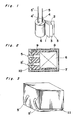
- Fig. 1 shows a capacitor element to which the present application is applied.
- aluminum foils having a purity higher than 99.99% are subjected to etching treatment in order to increase the effective surface area of them.
- oxidized membranes membranes of oxidized aluminum
- An anode foil 1 comprised of the aluminum foil processed as mentioned above and an opposing cathode foil 2 are rolled up into a cylinder putting a Manila paper as a separator inbetween these foils.
- a capacitor element 6 is formed, as shown in Fig. 1.
- Reference numerals 4 and 4′ indicate aluminum leads and reference numerals 5 and 5′ indicate lead wires.
- the capacitor element 6 is subjected to a heat treatment for carbonizing the Manila paper as the separator 3 to lower the density thereof by thinning fibers thereof.
- Fig. 2 is a sectional view of a capacitor of chip type wherein the capacitor element 6 shown in Fig. 1 is enclosed in an aluminum case 7 and Fig. 3 is an appearance of the capacitor of chip type.
- predetermined quantities of TCNQ complexes 8 are charged into the aluminum case 7 and the latter is put on a heat plate (not shown).
- the aluminum case 7 is heated up at a temperature equal to or higher than 210°C to liquefy the TCNQ complexes charged thereinto.
- the capacitor element 6 preheated is inserted in the aluminum case 7 to impregnate the liquefied TCNQ complexes into the capacitor element 6. And, immediately, the TCNQ complexes are solidified by cooling. Thereafter, a resin 9 being not reactive with the TCNQ complexes is charged into the aluminum case 7 and the opening of the case 7 is sealed with an epoxy resin 10.
- the aluminum case 7 has grooves 11 formed along bottom edges thereof into which lead wires 5, 5′ are inserted.
- TCNQ complexes having melting points higher than about 230°C are shown in Table 1.
- Table 1 there are also listed up electrical characteristics of capacitors made by using respective TCNQ complexes.
- Complex symbol (I) in Table 1 indicates a conventional TCNQ complex used in conventional solid electrolyte capacitors.
- Lutidine used for compositing TCNQ complexes indicated by complex symbols (A), (B) and (H) is 3.5-lutidine exactly and phenylpyridine used for compositing TCNQ complexes indicated by complex symbols (C), (D) and (E) is 4-phenylpyridine exactly.
- specifications of the capacitor used were 25 volts in the voltage and 0.68 ⁇ F in the capacitance.
- Table 2 contains results obtained when capacitors were made using various mixtures of the same quantity of TCNQ complexes listed up in Table 1 and those obtained in a reflow test made under thermal conditions supposed to be caused upon mounting capacitors using reflow solder. In the reflow test, capacitors were leaved at 160 °C for two minutes and subsequently, were leaved at 230 °C for 30 seconds in a reflow furnace.
- mixtures of at least two kinds of TCNQ complexes having cations different from each other as an electrolyte for solid electrolyte capacitors can control increase of E.S.R. and can yield capacitors having the heat resistivity endurable against the heat applied upon mounting them on printed circuit boards.
- E.S.R. of a single TCNQ complex having a high melting point which is chosen in order only to improve the heat resistivity against the heat applied upon mounting capacitors becomes 7 to 27 times that of the conventional TCNQ, for instance, isoquinoline TCNQ (I) wherein the substituent at N atom is an alkyl group
- E.S.R. of the mixed TCNQ complex according to the present invention can be reduced to an order of 2.4 to 6 times that of the conventional one and, further, electrical characteristics of the capacitor after exposed to severe thermal conditions, according to the present invention, are kept substantially unchanged from the initial electrical characteristics.
- the capacitor element 6 as shown in Fig. 1 was impregnated with N-n-buthylisoquinoline (TCNQ)2 and, then, it was sealed with the resins 9 and 10 in the aluminum case 7 as shown in Fig. 2.
- TCNQ N-n-buthylisoquinoline
- the capacitors were aged under various conditions (A) to (E) cited below in a state that they were inserted in holes formed on the heat plate each of which has diameter slightly larger than that of the capacitor and a depth larger than the height of the capacitor.
- Results of this aging test are listed up in Table 3. Ten samples were used per each aging condition and, therefore, each of values listed in Table 3 was a value obtained by averaging over ten samples.
- the melting point of N-n-buthylisoquinoline (TCNQ)2 used in the preferred embodiment ranged from 210 °C to 220 °C. Further, the aging voltage to be applied to the capacitor during aging was so called reduction voltage which was decreased as the heating temperature was increased.
- Capacitors were prepared using capacitor elements 6 as shown in Fig. 1 and a mixture of TCNQ complexes of the same quantity comprised of N, N-Penthamethylene (lutidinium)2 (TCNQ)4 and N-n-propylphenylpyridinium (TCNQ)2.
- Each capacitor 6 was enclosed by curing with a buthyl rubber molded and sealded therewith, as shown in Fig. 2. Specifications of this capacitor were of 25 volts in the voltage and 1 ⁇ F in the capacitance.
- the aging time needed in the manufacturing process of capacitors can be shortened extremely and reduction of processing steps and symplification of the aging equipment can be achieved.
- capacitors having heat resistivities being excellent in the electrical characteristics especially in the leakage current property can be obtained.
- Capacitor elements of roll type are mentioned in the present preferred embodiment, however, the present invention is applicable to capacitors using anode elements made by sintering molded bodies of powder metal such as aluminum, tantalum and/or niobium and at least one TCNQ complex as an electrolyte.
Landscapes
- Chemical & Material Sciences (AREA)
- Chemical Kinetics & Catalysis (AREA)
- Electrochemistry (AREA)
- Engineering & Computer Science (AREA)
- Power Engineering (AREA)
- Microelectronics & Electronic Packaging (AREA)
- Fixed Capacitors And Capacitor Manufacturing Machines (AREA)
Applications Claiming Priority (6)
| Application Number | Priority Date | Filing Date | Title |
|---|---|---|---|
| JP1271589 | 1989-01-20 | ||
| JP12715/89 | 1989-01-20 | ||
| JP1100769A JPH0744131B2 (ja) | 1989-04-20 | 1989-04-20 | 固体電解コンデンサの製造方法 |
| JP100769/89 | 1989-04-20 | ||
| JP270614/89 | 1989-10-18 | ||
| JP1270614A JPH0722076B2 (ja) | 1989-01-20 | 1989-10-18 | 固体電解コンデンサ |
Publications (3)
| Publication Number | Publication Date |
|---|---|
| EP0379213A2 true EP0379213A2 (fr) | 1990-07-25 |
| EP0379213A3 EP0379213A3 (fr) | 1991-11-21 |
| EP0379213B1 EP0379213B1 (fr) | 1996-10-09 |
Family
ID=27279959
Family Applications (1)
| Application Number | Title | Priority Date | Filing Date |
|---|---|---|---|
| EP90101091A Expired - Lifetime EP0379213B1 (fr) | 1989-01-20 | 1990-01-19 | Condensateur à électrolyte solide et son procédé de fabrication |
Country Status (4)
| Country | Link |
|---|---|
| US (1) | US5031077A (fr) |
| EP (1) | EP0379213B1 (fr) |
| CA (1) | CA2007997C (fr) |
| DE (1) | DE69028790T2 (fr) |
Cited By (1)
| Publication number | Priority date | Publication date | Assignee | Title |
|---|---|---|---|---|
| EP0558392A1 (fr) * | 1992-02-28 | 1993-09-01 | Compagnie Europeenne De Composants Electroniques Lcc | Procédé de stabilisation d'un complexe à transfert de charge basé sur le 7,7,8,8-tétracyanoquinodiméthane |
Families Citing this family (5)
| Publication number | Priority date | Publication date | Assignee | Title |
|---|---|---|---|---|
| US5766271A (en) * | 1994-11-24 | 1998-06-16 | Sanyo Electric Co., Ltd. | Process for producing solid electrolyte capacitor |
| TWI267507B (en) | 2000-12-05 | 2006-12-01 | Ind Tech Res Inst | TCNQ composite salt and application on solid capacitor of the same |
| US7736398B2 (en) * | 2007-02-26 | 2010-06-15 | Kaneka Corporation | Method of manufacturing conductive polymer electrolytic capacitor |
| CN104882279B (zh) * | 2015-05-28 | 2018-03-09 | 南通华裕电子有限公司 | 一种高比容铝电解电容器老化方法 |
| CN116043249B (zh) * | 2021-10-28 | 2025-11-14 | 中国石油化工股份有限公司 | 电解丙烯腈制己二腈的电解液及电解方法 |
Family Cites Families (8)
| Publication number | Priority date | Publication date | Assignee | Title |
|---|---|---|---|---|
| JPS5533146B1 (fr) * | 1970-03-04 | 1980-08-29 | ||
| JPS5610777B2 (fr) * | 1972-06-13 | 1981-03-10 | ||
| US4580855A (en) * | 1981-04-17 | 1986-04-08 | Sanyo Electric Co., Ltd. | Solid electrolyte capacitor |
| GB2113916B (en) * | 1982-01-18 | 1986-07-09 | Sanyo Electric Co | Solid electrolyte capacitor |
| CA1245311A (fr) * | 1984-02-10 | 1988-11-22 | Takato Ito | Condensateur a electrolyte organique semiconducteur, et sa fabrication |
| US4679124A (en) * | 1985-01-14 | 1987-07-07 | Matsushita Electric Industrial Co., Ltd. | Solid electrolytic capacitors |
| DE3686914T2 (de) * | 1985-07-17 | 1993-02-18 | Nippon Chemicon | Elektrolyt fuer elektrolytkondensator. |
| JPS63126212A (ja) * | 1986-11-14 | 1988-05-30 | 松下電器産業株式会社 | 固体電解コンデンサ |
-
1990
- 1990-01-12 US US07/472,983 patent/US5031077A/en not_active Expired - Lifetime
- 1990-01-17 CA CA002007997A patent/CA2007997C/fr not_active Expired - Fee Related
- 1990-01-19 EP EP90101091A patent/EP0379213B1/fr not_active Expired - Lifetime
- 1990-01-19 DE DE69028790T patent/DE69028790T2/de not_active Expired - Fee Related
Cited By (2)
| Publication number | Priority date | Publication date | Assignee | Title |
|---|---|---|---|---|
| EP0558392A1 (fr) * | 1992-02-28 | 1993-09-01 | Compagnie Europeenne De Composants Electroniques Lcc | Procédé de stabilisation d'un complexe à transfert de charge basé sur le 7,7,8,8-tétracyanoquinodiméthane |
| FR2688002A1 (fr) * | 1992-02-28 | 1993-09-03 | Europ Composants Electron | Procede de stabilisation d'un complexe a transfert de charge base sur le 7,7,8,8-tetracyanoquinodimethane. |
Also Published As
| Publication number | Publication date |
|---|---|
| DE69028790T2 (de) | 1997-05-07 |
| CA2007997C (fr) | 2000-03-07 |
| DE69028790D1 (de) | 1996-11-14 |
| US5031077A (en) | 1991-07-09 |
| EP0379213A3 (fr) | 1991-11-21 |
| EP0379213B1 (fr) | 1996-10-09 |
| CA2007997A1 (fr) | 1990-07-20 |
Similar Documents
| Publication | Publication Date | Title |
|---|---|---|
| US5790368A (en) | Capacitor and manufacturing method thereof | |
| JPH04229611A (ja) | 固体電解コンデンサ | |
| DE69400568T2 (de) | Herstellungsverfahren von einem Festelektrolytkondensator | |
| US4876451A (en) | Aluminum solid electrolytic capacitor and manufacturing method thereof | |
| EP0464605B1 (fr) | Condensateur à électrolyte solide comportant un semi-conducteur organique et son procédé de fabrication | |
| US7167357B2 (en) | Surface mount MELF capacitor | |
| EP0379213A2 (fr) | Condensateur à électrolyte solide et son procédé de fabrication | |
| US4679124A (en) | Solid electrolytic capacitors | |
| EP0285728B1 (fr) | Condensateur électrolytique solide et son procédé de fabrication | |
| US4828738A (en) | Solid electrolytic capacitor | |
| KR0154126B1 (ko) | 고체 전해 콘덴서 및 그의 제조방법 | |
| JP3123772B2 (ja) | 有機半導体固体電解コンデンサ | |
| JP3326196B2 (ja) | 固体電解コンデンサの製造方法 | |
| JP2869145B2 (ja) | 固体電解コンデンサの製造方法 | |
| JP3162738B2 (ja) | 固体電解コンデンサ | |
| JP2726009B2 (ja) | 固体電解コンデンサ | |
| JP3474986B2 (ja) | 固体電解コンデンサ及びその製造方法 | |
| CN116913688A (zh) | 一种滤波电容器 | |
| JP2942451B2 (ja) | 有機電解質電池の製造方法 | |
| JPS59197123A (ja) | 電解コンデンサおよびその製造方法 | |
| JP3438900B2 (ja) | 固体電解コンデンサ | |
| JP3296717B2 (ja) | 固体電解コンデンサ及びその製造方法 | |
| KR970006432B1 (ko) | 고체 전해 콘덴서 | |
| JP2771767B2 (ja) | 固体電解コンデンサの製造方法 | |
| JPH08330190A (ja) | チップ型固体電解コンデンサ及びその製造方法 |
Legal Events
| Date | Code | Title | Description |
|---|---|---|---|
| PUAI | Public reference made under article 153(3) epc to a published international application that has entered the european phase |
Free format text: ORIGINAL CODE: 0009012 |
|
| AK | Designated contracting states |
Kind code of ref document: A2 Designated state(s): DE FR GB NL |
|
| 17P | Request for examination filed |
Effective date: 19901207 |
|
| PUAL | Search report despatched |
Free format text: ORIGINAL CODE: 0009013 |
|
| AK | Designated contracting states |
Kind code of ref document: A3 Designated state(s): DE FR GB NL |
|
| 17Q | First examination report despatched |
Effective date: 19931228 |
|
| GRAH | Despatch of communication of intention to grant a patent |
Free format text: ORIGINAL CODE: EPIDOS IGRA |
|
| GRAH | Despatch of communication of intention to grant a patent |
Free format text: ORIGINAL CODE: EPIDOS IGRA |
|
| GRAA | (expected) grant |
Free format text: ORIGINAL CODE: 0009210 |
|
| AK | Designated contracting states |
Kind code of ref document: B1 Designated state(s): DE FR GB NL |
|
| REF | Corresponds to: |
Ref document number: 69028790 Country of ref document: DE Date of ref document: 19961114 |
|
| ET | Fr: translation filed | ||
| PLBE | No opposition filed within time limit |
Free format text: ORIGINAL CODE: 0009261 |
|
| STAA | Information on the status of an ep patent application or granted ep patent |
Free format text: STATUS: NO OPPOSITION FILED WITHIN TIME LIMIT |
|
| 26N | No opposition filed | ||
| REG | Reference to a national code |
Ref country code: GB Ref legal event code: IF02 |
|
| PGFP | Annual fee paid to national office [announced via postgrant information from national office to epo] |
Ref country code: DE Payment date: 20070111 Year of fee payment: 18 |
|
| PGFP | Annual fee paid to national office [announced via postgrant information from national office to epo] |
Ref country code: NL Payment date: 20070115 Year of fee payment: 18 |
|
| PGFP | Annual fee paid to national office [announced via postgrant information from national office to epo] |
Ref country code: GB Payment date: 20070117 Year of fee payment: 18 |
|
| PGFP | Annual fee paid to national office [announced via postgrant information from national office to epo] |
Ref country code: FR Payment date: 20070109 Year of fee payment: 18 |
|
| GBPC | Gb: european patent ceased through non-payment of renewal fee |
Effective date: 20080119 |
|
| NLV4 | Nl: lapsed or anulled due to non-payment of the annual fee |
Effective date: 20080801 |
|
| PG25 | Lapsed in a contracting state [announced via postgrant information from national office to epo] |
Ref country code: NL Free format text: LAPSE BECAUSE OF NON-PAYMENT OF DUE FEES Effective date: 20080801 Ref country code: DE Free format text: LAPSE BECAUSE OF NON-PAYMENT OF DUE FEES Effective date: 20080801 |
|
| REG | Reference to a national code |
Ref country code: FR Ref legal event code: ST Effective date: 20081029 |
|
| PG25 | Lapsed in a contracting state [announced via postgrant information from national office to epo] |
Ref country code: GB Free format text: LAPSE BECAUSE OF NON-PAYMENT OF DUE FEES Effective date: 20080119 |
|
| PG25 | Lapsed in a contracting state [announced via postgrant information from national office to epo] |
Ref country code: FR Free format text: LAPSE BECAUSE OF NON-PAYMENT OF DUE FEES Effective date: 20080131 |