EP0379293A2 - Commande d'un onduleur de puissance - Google Patents
Commande d'un onduleur de puissance Download PDFInfo
- Publication number
- EP0379293A2 EP0379293A2 EP90300240A EP90300240A EP0379293A2 EP 0379293 A2 EP0379293 A2 EP 0379293A2 EP 90300240 A EP90300240 A EP 90300240A EP 90300240 A EP90300240 A EP 90300240A EP 0379293 A2 EP0379293 A2 EP 0379293A2
- Authority
- EP
- European Patent Office
- Prior art keywords
- frequency
- power inverter
- timing waveform
- inverter
- prf
- Prior art date
- Legal status (The legal status is an assumption and is not a legal conclusion. Google has not performed a legal analysis and makes no representation as to the accuracy of the status listed.)
- Withdrawn
Links
- 238000010586 diagram Methods 0.000 description 2
- 238000009499 grossing Methods 0.000 description 2
- 238000001914 filtration Methods 0.000 description 1
- 238000005259 measurement Methods 0.000 description 1
- 238000012544 monitoring process Methods 0.000 description 1
- 230000003287 optical effect Effects 0.000 description 1
- 230000001360 synchronised effect Effects 0.000 description 1
- 238000004804 winding Methods 0.000 description 1
Images
Classifications
-
- H—ELECTRICITY
- H03—ELECTRONIC CIRCUITRY
- H03L—AUTOMATIC CONTROL, STARTING, SYNCHRONISATION OR STABILISATION OF GENERATORS OF ELECTRONIC OSCILLATIONS OR PULSES
- H03L7/00—Automatic control of frequency or phase; Synchronisation
- H03L7/06—Automatic control of frequency or phase; Synchronisation using a reference signal applied to a frequency- or phase-locked loop
- H03L7/16—Indirect frequency synthesis, i.e. generating a desired one of a number of predetermined frequencies using a frequency- or phase-locked loop
- H03L7/18—Indirect frequency synthesis, i.e. generating a desired one of a number of predetermined frequencies using a frequency- or phase-locked loop using a frequency divider or counter in the loop
- H03L7/183—Indirect frequency synthesis, i.e. generating a desired one of a number of predetermined frequencies using a frequency- or phase-locked loop using a frequency divider or counter in the loop a time difference being used for locking the loop, the counter counting between fixed numbers or the frequency divider dividing by a fixed number
- H03L7/185—Indirect frequency synthesis, i.e. generating a desired one of a number of predetermined frequencies using a frequency- or phase-locked loop using a frequency divider or counter in the loop a time difference being used for locking the loop, the counter counting between fixed numbers or the frequency divider dividing by a fixed number using a mixer in the loop
-
- H—ELECTRICITY
- H03—ELECTRONIC CIRCUITRY
- H03B—GENERATION OF OSCILLATIONS, DIRECTLY OR BY FREQUENCY-CHANGING, BY CIRCUITS EMPLOYING ACTIVE ELEMENTS WHICH OPERATE IN A NON-SWITCHING MANNER; GENERATION OF NOISE BY SUCH CIRCUITS
- H03B9/00—Generation of oscillations using transit-time effects
- H03B9/01—Generation of oscillations using transit-time effects using discharge tubes
- H03B9/08—Generation of oscillations using transit-time effects using discharge tubes using a travelling-wave tube
Definitions
- Power inverters particularly those used as power supplies for radar systems, are generally of the free-running type with a switching frequency of up to say 150 KHz. In normal circumstances the switching frequency is of little importance. However in some applications the switching frequency may cause noise to be introduced, particularly if the apparatus supplied with power is, itself controlled by a timing signal.
- the cathode of the tube it is common to use the cathode of the tube as a voltage reference for the tube power supplies so that the modulator may be connected directly to the electrodes of the travelling-wave tube. This results in a risk of noise being added to the RF output waveform of the tube. Such noise may be minimised by filtering but this incurs a size and weight penalty, particularly in the case of heater supplies because of the high currents involved.
- apparatus for controlling the operation of a switch mode power inverter having a known limited maximum-to-minimum operating frequency ratio in dependence upon a variable-frequency timing wave form having a greater operating frequency ratio which includes measuring means for measuring the frequency of the timing waveform from time to time, and circuit means responsive to the output of the measuring means to generate a synchronising pulse train for application to the power inverter and having a frequency which is an integral multiple or sub-multiple of the frequency of the timing waveform and which is within the operating range of the power inverter.
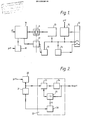
- FIG. 1 shows a switch mode power inverter 10 having a dc power supply input and applying ac output power to a transformer 11.
- the transformer has several secondary windings which supply power at different voltages to rectifying and smoothing units which provide power for the grid, cathode and heater of the travelling-wave tube 12.
- the rectifying and smoothing units are shown schematically at 13.
- Figure 1 also shows the heater supply regulator 14 and output switch 15, as well as a fault-monitoring unit 16 which passes signals back through an optical isolator 17 to the power inverter 10.
- the frequency of operation of the power inverter is controlled by the control means 18.
- the frequency of operation of the switched mode power supply may be controlled over a maximum-to-minimum frequency ratio of perhaps 3 or 4:1 at most, this control being exerted by the control means 18.
- the prf of the transmitter may have to vary over a range having a maximum-to-minimum frequency ratio as large as 100:1, though the prf will always be lower than the operating frequency of the power inverter. It has been found that noise introduced by the power inverter into the output of the travelling-wave tube is at a minimum when the frequency of operator of the power inverter is an integral multiple of the prf and it is the purpose of the control means to produce this synchronisation.
- the control means 18 of Figure 1 is shown in greater detail in Figure 2.
- the timing waveform in this case a sample of the prf signal, is applied to a pulse shaper 20 which produces constant amplitude and constant pulse width replicas of the original prf pulses.
- This waveform is applied to a frequency counter 21 which measures the frequency of that timing waveform at predetermined intervals.
- the shaped prf signal is also applied to circuit means 22 including a conventional phase-locked loop comprising a phase detector 23, a voltage controlled oscillator 24 and a "-n" circuit 25.
- the output of the phase-locked loop is a pulse train having a frequency which is a multiple of the prf.
- the signal applied to the divider circuit 25 is such that the output of the voltage controlled oscillator 24 is the desired multiple N of the prf.
- This signal is produced by a processor 26 which is supplied with a signal indicating the actual measured frequency of the prf signal and also stores details of the workable frequency range of the power inverter and of other necessary characteristics of the inverter. By way of example only, consider the situation with a power inverter which requires an applied trigger pulse to produce one half-cycle of the desired output.
- the trigger or synchronising pulses must be provided at a frequency between 100KHz and 240KHz. Assume also that the prf of the associated radar for which the power supply is used is in the range from 30KHz to 120KHz. The processor 26 must therefore operate to ensure that the multiplier N lies in the range of the inverter.
- the output of the frequency counter 21 indicates the actual prf of the radar at the time of measurement.
- the output N from the processor may conveniently be a digital signal applied to the divider circuit 25.
- the use of an inverter to supply a travelling-wave tube is only one example of the manner in which the invention may be used.
- the pulse rate of the timing waveform with which the inverter is to be synchronised may be greater than the inverter operating frequency, in which case the ratio N will have to be an integral sub-multiple of the pulse rate of the timing waveform.
- the rate at which the frequency counter 21 measures the frequency of the timing waveform will depend upon the nature of the source of the timing wave form. Clearly if the timing waveform changes its prf frequently, as for example in the case of a frequency-agile radar, then frequent checks on the prf will be necessary.
- the wound components of the inverter need be no larger than those used in a fixed frequency power inverter.
Landscapes
- Inverter Devices (AREA)
Applications Claiming Priority (2)
| Application Number | Priority Date | Filing Date | Title |
|---|---|---|---|
| GB8900816A GB2227133A (en) | 1989-01-14 | 1989-01-14 | Control of power inverter |
| GB8900816 | 1989-01-14 |
Publications (2)
| Publication Number | Publication Date |
|---|---|
| EP0379293A2 true EP0379293A2 (fr) | 1990-07-25 |
| EP0379293A3 EP0379293A3 (fr) | 1991-07-03 |
Family
ID=10650041
Family Applications (1)
| Application Number | Title | Priority Date | Filing Date |
|---|---|---|---|
| EP19900300240 Withdrawn EP0379293A3 (fr) | 1989-01-14 | 1990-01-09 | Commande d'un onduleur de puissance |
Country Status (2)
| Country | Link |
|---|---|
| EP (1) | EP0379293A3 (fr) |
| GB (1) | GB2227133A (fr) |
Cited By (2)
| Publication number | Priority date | Publication date | Assignee | Title |
|---|---|---|---|---|
| WO2011002365A1 (fr) | 2009-07-01 | 2011-01-06 | Saab Ab | Système radar comprenant un convertisseur de puissance à mode de commutation |
| EP1973138A3 (fr) * | 2007-03-19 | 2015-08-12 | NETCOMSEC Co., Ltd | Unité d'alimentation électrique, système de circuit haute fréquence et procédé de contrôle de la tension d'un chauffage |
Families Citing this family (1)
| Publication number | Priority date | Publication date | Assignee | Title |
|---|---|---|---|---|
| SE0102303D0 (sv) | 2001-06-27 | 2001-06-27 | Ericsson Telefon Ab L M | DC/DC converter |
-
1989
- 1989-01-14 GB GB8900816A patent/GB2227133A/en not_active Withdrawn
-
1990
- 1990-01-09 EP EP19900300240 patent/EP0379293A3/fr not_active Withdrawn
Non-Patent Citations (1)
| Title |
|---|
| PROCEEDINGS OF THE 20TH INTERSOCIETY ENERGY CONVERSION ENGINEERING CONFERENCE, Warrendale, PA, August 1985, vol. 1, pages 1696-1701; H.K. ASPER: "Sinewave synthesis for high efficiency DC-AC conversion" * |
Cited By (5)
| Publication number | Priority date | Publication date | Assignee | Title |
|---|---|---|---|---|
| EP1973138A3 (fr) * | 2007-03-19 | 2015-08-12 | NETCOMSEC Co., Ltd | Unité d'alimentation électrique, système de circuit haute fréquence et procédé de contrôle de la tension d'un chauffage |
| EP3021346A1 (fr) * | 2007-03-19 | 2016-05-18 | Nec Network And Sensor Systems, Ltd. | Unité d'alimentation électrique, système de circuit haute fréquence et procédé de contrôle de la tension d'un chauffage |
| WO2011002365A1 (fr) | 2009-07-01 | 2011-01-06 | Saab Ab | Système radar comprenant un convertisseur de puissance à mode de commutation |
| EP2449401A4 (fr) * | 2009-07-01 | 2014-08-27 | Saab Ab | Système radar comprenant un convertisseur de puissance à mode de commutation |
| US9013346B2 (en) | 2009-07-01 | 2015-04-21 | Saab Ab | Radar system comprising a switching mode power converter |
Also Published As
| Publication number | Publication date |
|---|---|
| EP0379293A3 (fr) | 1991-07-03 |
| GB8900816D0 (en) | 1989-03-08 |
| GB2227133A (en) | 1990-07-18 |
Similar Documents
| Publication | Publication Date | Title |
|---|---|---|
| KR850008069A (ko) | 전원시스템 및 그의 제어방법 | |
| KR970055156A (ko) | 공진형 콘버터 제어 시스템 | |
| US3992670A (en) | Frequency control circuits such as for use in modulation measurement | |
| KR890013934A (ko) | 선동기 검파회로 | |
| GB2227133A (en) | Control of power inverter | |
| US5397988A (en) | Method and device for tuning a HF source, in particular for tuning a microwave source of an electron spin resonance spectrometer | |
| US3760256A (en) | Synchronous dc power supply | |
| US3344361A (en) | Phase controlled oscillator loop including an electronic counter | |
| US4320355A (en) | Sweep signal generation system | |
| KR970062504A (ko) | 고주파 유도가열 조리장치 | |
| US2748285A (en) | Start-stop oscillator | |
| JPH0292118A (ja) | 位相同期発振器 | |
| US2818505A (en) | Control circuit | |
| JP3720120B2 (ja) | 波形生成装置 | |
| Saegusa et al. | Digital phase meter using relative counting A/D conversion system | |
| JPS5511653A (en) | Frequency converting device | |
| SU1111262A1 (ru) | Ретгеновский генератор | |
| SU851700A1 (ru) | Преобразователь посто нного напр жени В пЕРЕМЕННОЕ | |
| JPS5858869A (ja) | 位相同期制御回路 | |
| KR970060704A (ko) | 초음파 발진 제어회로 | |
| JPS5644394A (en) | Controller for ac motor | |
| JPS57157636A (en) | Proximity switch circuit | |
| JPH01232828A (ja) | Pll回路 | |
| US2736804A (en) | Oscillator synchronization | |
| JPH06305705A (ja) | オゾン発生器用電源装置 |
Legal Events
| Date | Code | Title | Description |
|---|---|---|---|
| PUAI | Public reference made under article 153(3) epc to a published international application that has entered the european phase |
Free format text: ORIGINAL CODE: 0009012 |
|
| AK | Designated contracting states |
Kind code of ref document: A2 Designated state(s): DE FR IT SE |
|
| RAP1 | Party data changed (applicant data changed or rights of an application transferred) |
Owner name: FERRANTI INTERNATIONAL PLC |
|
| RAP1 | Party data changed (applicant data changed or rights of an application transferred) |
Owner name: GEC-FERRANTI DEFENCE SYSTEMS LTD. |
|
| PUAL | Search report despatched |
Free format text: ORIGINAL CODE: 0009013 |
|
| AK | Designated contracting states |
Kind code of ref document: A3 Designated state(s): DE FR IT SE |
|
| 17P | Request for examination filed |
Effective date: 19911029 |
|
| 17Q | First examination report despatched |
Effective date: 19920429 |
|
| STAA | Information on the status of an ep patent application or granted ep patent |
Free format text: STATUS: THE APPLICATION IS DEEMED TO BE WITHDRAWN |
|
| 18D | Application deemed to be withdrawn |
Effective date: 19920801 |