EP0379318A1 - Ouverture pour un gyroscope laser modulaire en anneau - Google Patents
Ouverture pour un gyroscope laser modulaire en anneau Download PDFInfo
- Publication number
- EP0379318A1 EP0379318A1 EP90300387A EP90300387A EP0379318A1 EP 0379318 A1 EP0379318 A1 EP 0379318A1 EP 90300387 A EP90300387 A EP 90300387A EP 90300387 A EP90300387 A EP 90300387A EP 0379318 A1 EP0379318 A1 EP 0379318A1
- Authority
- EP
- European Patent Office
- Prior art keywords
- ring laser
- aperturing
- laser gyroscope
- orifice
- lasing
- Prior art date
- Legal status (The legal status is an assumption and is not a legal conclusion. Google has not performed a legal analysis and makes no representation as to the accuracy of the status listed.)
- Withdrawn
Links
- 230000000644 propagated effect Effects 0.000 abstract 1
- 230000003287 optical effect Effects 0.000 description 4
- 239000006094 Zerodur Substances 0.000 description 2
- 238000004519 manufacturing process Methods 0.000 description 2
- 238000000034 method Methods 0.000 description 2
- 241000656145 Thyrsites atun Species 0.000 description 1
- 238000005266 casting Methods 0.000 description 1
- 229910010293 ceramic material Inorganic materials 0.000 description 1
- 230000001427 coherent effect Effects 0.000 description 1
- 239000003989 dielectric material Substances 0.000 description 1
- 238000005553 drilling Methods 0.000 description 1
- 239000003822 epoxy resin Substances 0.000 description 1
- 230000005284 excitation Effects 0.000 description 1
- 239000011521 glass Substances 0.000 description 1
- 239000002241 glass-ceramic Substances 0.000 description 1
- 239000000463 material Substances 0.000 description 1
- 238000000465 moulding Methods 0.000 description 1
- 239000004033 plastic Substances 0.000 description 1
- 229920003023 plastic Polymers 0.000 description 1
- 229920000647 polyepoxide Polymers 0.000 description 1
- 230000001902 propagating effect Effects 0.000 description 1
Images
Classifications
-
- G—PHYSICS
- G01—MEASURING; TESTING
- G01C—MEASURING DISTANCES, LEVELS OR BEARINGS; SURVEYING; NAVIGATION; GYROSCOPIC INSTRUMENTS; PHOTOGRAMMETRY OR VIDEOGRAMMETRY
- G01C19/00—Gyroscopes; Turn-sensitive devices using vibrating masses; Turn-sensitive devices without moving masses; Measuring angular rate using gyroscopic effects
- G01C19/58—Turn-sensitive devices without moving masses
- G01C19/64—Gyrometers using the Sagnac effect, i.e. rotation-induced shifts between counter-rotating electromagnetic beams
- G01C19/66—Ring laser gyrometers
- G01C19/661—Ring laser gyrometers details
Definitions
- ring laser gyroscopes have their bodies formed from a single block of dielectric material having a low coefficient of thermal expansion, for example Zerodur (Registered Trade Mark). Bores are drilled in the monoblock (as the block is known) to define each limb of the lasing cavity as well as extra bores leading to electrodes to enable DC excitation of the gas in the lasing capacity.
- Each lasing cavity has a lasing path, the lasing path being polygonal with mirrors at each corner. The lasing path forms a closed loop within which two laser beams travel in opposite directions.
- Laser light beam propagates within the cavity as a standing-wave configuration along its length. However, it may also sustain a standing-wave across its width thereby creating transverse modes. These are known as TEM mn modes (Transverse Electric and Magnetic). The m and n subscripts are the integer number of transverse nodal lines in the orthogonal directions across the beam width. The lowest order or TEM oo transverse mode is completely spatially coherent and therefore will produce optimum laser gyro performance. To obtain pure TEM oo operation the laser beam passes through an aperture to restrict the diameter of the beam and preventing other transverse modes from propagating.
- TEM mn modes Transverse Electric and Magnetic
- the bores, or a portion of the bores forming the laser cavities are drilled sufficiently narrowly to form an aperture and thereby ensuring that the TEM oo mode beam propagates in each direction in the lasing path. This demands great accuracy during drilling and in subsequent positioning of the mirrors.
- the optical alignment of a laser gyro is achieved by adjusting the mirror positions to cause the laser beam path to move with respect to the fixed aperture.
- the position of the laser beam path is very sensitive to small mirror adjustments thereby making perfect alignment difficult to achieve.
- Optical alignment of a triaxial laser gyroscope can be more difficult to achieve because each mirror is shared between adjacent lasing axes. As each mirror aligns the laser beam to the aperture of one of the lasing axis the laser beam can be misaligned in the adjacent axis.
- a ring laser gyroscope whose body is formed of modules which are assembled prior to use, includes for each lasing path, aperture support means, and aperturing means adjustably carried thereby the aperturing laser beam means having an orifice of a size chosen to allow passage of one transverse mode in each direction through it, the arrangement being such that the orifice can be positioned during assembly of the ring laser gyroscope and subsequently held permanently in that position so that in use only one transverse mode is allowed to pass through it.
- the aperture support means comprises a shoulder having a large cutaway or hole formed therethrough
- the aperturing means comprises a plate with an orifice formed in it, the plate being capable of being permanently bonded in a chosen position on the shoulder.
- the plate is in the form of a disc.
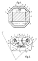
- Figure 1 is a cross sectional view of a modular ring laser gyroscope body - in this example a tri-axis instrument in which the mirrors are shared by more than one lasing path
- Figure 2 is an isometric view of a mirror module forming part of the gyroscope body of Figure 1.
- Figure 1 The cross section of Figure 1 is in the plane of one lasing path eg: that referenced X-X of Figure 2.
- a tri-axis ring laser gyroscope 1 comprises two mirror modules 2 and 3 and a gain bore module 4 lying between them.
- the modules are assembled in a sealed gas tight manner during manufacture. They are formed of Zerodur, which is a type of glass, a ceramic material, a glass-ceramic, or even of a plastics material.
- Each mirror module 2,3 is formed with an internal surface 5 on which is mounted three mirrors 6,7,8.
- the module 2 is further provided with radially inwardly directed shoulders 9,10,11 extending from the inner part-spherical surface to lie at right angles across each lasing path each respectively shown in part at 12,13,14.
- Each lasing path is rectangular and lies orthogonally to the others. Naturally each path is completed by the mirrors in that module referenced 3. An example, ie: path 12 is shown complete in Figure 1.
- Each shoulder has a cutaway region 15, either a slot or a hole of sufficient size to allow a multi-transverse mode laser beam to pass there through with clearance.
- Each shoulder is provided with aperturing means 16 comprising a disc with an orifice 17 formed in it, the size of the orifice being such that just the TEM oo mode propagates in each of the counter-rotating beams is allowed to pass through instead of multi-transverse modes. Sufficient adjustment is provided by the size of the disc 16 and the cutaway region 15 to allow a selected pair of transverse mode to be passed whilst the remainder are blocked.
- the discs 16 are set permanently in position by an epoxy resin - preferably one with ultra-violet light curing characteristics.
- the apertures are aligned and secured, following the mirror alignment. Therefore, as each aperture is dedicated to only one of the lasing axes, perfect optical alignment is always possible.
- the shoulders 9,10,11 can be integrally formed during that process.
Landscapes
- Physics & Mathematics (AREA)
- Engineering & Computer Science (AREA)
- Optics & Photonics (AREA)
- Electromagnetism (AREA)
- Power Engineering (AREA)
- General Physics & Mathematics (AREA)
- Radar, Positioning & Navigation (AREA)
- Remote Sensing (AREA)
- Gyroscopes (AREA)
Applications Claiming Priority (2)
| Application Number | Priority Date | Filing Date | Title |
|---|---|---|---|
| GB8900799 | 1989-01-14 | ||
| GB898900799A GB8900799D0 (en) | 1989-01-14 | 1989-01-14 | Modular rlg aperturing |
Publications (1)
| Publication Number | Publication Date |
|---|---|
| EP0379318A1 true EP0379318A1 (fr) | 1990-07-25 |
Family
ID=10650024
Family Applications (1)
| Application Number | Title | Priority Date | Filing Date |
|---|---|---|---|
| EP90300387A Withdrawn EP0379318A1 (fr) | 1989-01-14 | 1990-01-12 | Ouverture pour un gyroscope laser modulaire en anneau |
Country Status (3)
| Country | Link |
|---|---|
| EP (1) | EP0379318A1 (fr) |
| JP (1) | JPH02227609A (fr) |
| GB (1) | GB8900799D0 (fr) |
Cited By (1)
| Publication number | Priority date | Publication date | Assignee | Title |
|---|---|---|---|---|
| FR2680415A1 (fr) * | 1991-12-17 | 1993-02-19 | Sagem | Gyrometre laser en anneau, a diaphragme. |
Families Citing this family (1)
| Publication number | Priority date | Publication date | Assignee | Title |
|---|---|---|---|---|
| CN113137960B (zh) * | 2021-05-18 | 2025-05-13 | 湖南二零八先进科技有限公司 | 一种模块化的超大型激光陀螺谐振腔及其制造方法 |
Citations (4)
| Publication number | Priority date | Publication date | Assignee | Title |
|---|---|---|---|---|
| FR2030688A5 (fr) * | 1969-02-05 | 1970-11-13 | Honeywell Inc | |
| FR2548777A1 (fr) * | 1983-07-05 | 1985-01-11 | Litton Systems Inc | Ensemble a gyroscope a laser en anneau et procede de fabrication d'un miroir de laser |
| US4705398A (en) * | 1985-05-20 | 1987-11-10 | Northrop Corporation | Pentagonal ring laser gyro design |
| EP0320101A1 (fr) * | 1987-12-10 | 1989-06-14 | British Aerospace Public Limited Company | Gyroscopes de laser en anneau |
-
1989
- 1989-01-14 GB GB898900799A patent/GB8900799D0/en active Pending
-
1990
- 1990-01-12 EP EP90300387A patent/EP0379318A1/fr not_active Withdrawn
- 1990-01-16 JP JP465390A patent/JPH02227609A/ja active Pending
Patent Citations (4)
| Publication number | Priority date | Publication date | Assignee | Title |
|---|---|---|---|---|
| FR2030688A5 (fr) * | 1969-02-05 | 1970-11-13 | Honeywell Inc | |
| FR2548777A1 (fr) * | 1983-07-05 | 1985-01-11 | Litton Systems Inc | Ensemble a gyroscope a laser en anneau et procede de fabrication d'un miroir de laser |
| US4705398A (en) * | 1985-05-20 | 1987-11-10 | Northrop Corporation | Pentagonal ring laser gyro design |
| EP0320101A1 (fr) * | 1987-12-10 | 1989-06-14 | British Aerospace Public Limited Company | Gyroscopes de laser en anneau |
Cited By (1)
| Publication number | Priority date | Publication date | Assignee | Title |
|---|---|---|---|---|
| FR2680415A1 (fr) * | 1991-12-17 | 1993-02-19 | Sagem | Gyrometre laser en anneau, a diaphragme. |
Also Published As
| Publication number | Publication date |
|---|---|
| GB8900799D0 (en) | 1989-03-08 |
| JPH02227609A (ja) | 1990-09-10 |
Similar Documents
| Publication | Publication Date | Title |
|---|---|---|
| EP0708996B1 (fr) | Laser a plaque a structure de resonateur repliee | |
| US5684822A (en) | Laser system with anamorphic confocal unstable resonator | |
| US4247832A (en) | Isotropic nonplanar ring laser | |
| US4284329A (en) | Laser gyroscope system | |
| FI80791C (fi) | Ringlasergyroskop. | |
| JPS6351392B2 (fr) | ||
| US4960331A (en) | Faraday rotator assembly | |
| RU99105608A (ru) | Лазерное устройство | |
| EP0379318A1 (fr) | Ouverture pour un gyroscope laser modulaire en anneau | |
| CA1309155C (fr) | Laser en anneau | |
| EP0764354A1 (fr) | Gyroscope a laser annulaire a solide et pompage par diodes | |
| US4548501A (en) | Laser gyroscope system | |
| CA1212748A (fr) | Capteur de vitesse angulaire pour laser a anneau | |
| EP0209279A1 (fr) | Gyroscope à laser en anneau | |
| US4705398A (en) | Pentagonal ring laser gyro design | |
| DE3780254T2 (de) | Ringlaserkreisel mit geometrisch induziertem "bias". | |
| EP0986150B1 (fr) | Laser à faisceau replie et à éléments multiples | |
| CA1098201A (fr) | Traduction non-disponible | |
| US4000947A (en) | Optical readout for differential laser gyros | |
| US5020911A (en) | Ring laser gyro comprising rotary oscillation apparatus | |
| US5781579A (en) | Microwave excited gas laser apparatus | |
| US5469256A (en) | Multipole magnetic geometry for a ring laser gyroscope | |
| US6618151B2 (en) | Ring laser gyroscope with offset aperture | |
| EP0390874B1 (fr) | Bloc laser annulaire de decharge luminescente a cathode creuse et structure d'electrode pour detecteurs de vitesse angulaire de laser annulaire | |
| US4847858A (en) | Optical resonator for a laser |
Legal Events
| Date | Code | Title | Description |
|---|---|---|---|
| PUAI | Public reference made under article 153(3) epc to a published international application that has entered the european phase |
Free format text: ORIGINAL CODE: 0009012 |
|
| 17P | Request for examination filed |
Effective date: 19900119 |
|
| AK | Designated contracting states |
Kind code of ref document: A1 Designated state(s): DE FR GB IT SE |
|
| 17Q | First examination report despatched |
Effective date: 19910704 |
|
| STAA | Information on the status of an ep patent application or granted ep patent |
Free format text: STATUS: THE APPLICATION IS DEEMED TO BE WITHDRAWN |
|
| 18D | Application deemed to be withdrawn |
Effective date: 19911115 |