EP0379321A2 - Mesure de différence de phase - Google Patents
Mesure de différence de phase Download PDFInfo
- Publication number
- EP0379321A2 EP0379321A2 EP90300399A EP90300399A EP0379321A2 EP 0379321 A2 EP0379321 A2 EP 0379321A2 EP 90300399 A EP90300399 A EP 90300399A EP 90300399 A EP90300399 A EP 90300399A EP 0379321 A2 EP0379321 A2 EP 0379321A2
- Authority
- EP
- European Patent Office
- Prior art keywords
- values
- signals
- phase difference
- quadrature
- phase
- Prior art date
- Legal status (The legal status is an assumption and is not a legal conclusion. Google has not performed a legal analysis and makes no representation as to the accuracy of the status listed.)
- Withdrawn
Links
- 238000005259 measurement Methods 0.000 title description 10
- 238000005070 sampling Methods 0.000 claims abstract description 32
- 230000015654 memory Effects 0.000 claims abstract description 5
- 238000000034 method Methods 0.000 claims description 15
- 238000012935 Averaging Methods 0.000 claims description 7
- 230000006870 function Effects 0.000 claims 1
- 239000013598 vector Substances 0.000 description 2
- 238000000926 separation method Methods 0.000 description 1
Images

Classifications
-
- G—PHYSICS
- G01—MEASURING; TESTING
- G01R—MEASURING ELECTRIC VARIABLES; MEASURING MAGNETIC VARIABLES
- G01R25/00—Arrangements for measuring phase angle between a voltage and a current or between voltages or currents
Definitions
- This invention relates to the measurement of the phase difference between two signals of equal frequency. Such a measurement is required in a number of circumstances, for example in the determination of the angle of arrival of a radar signal by the measurement of the phase difference between the signals from two adjacent elements of a phased array antenna.
- a method for measuring the phase difference between a plurality of signals of equal frequency comprises: quadrature sampling the signals using a plurality of quadrature sampling circuits, having a common local oscillator, so as to provide values of instantaneous phase in respect of each signal; deriving from the values of instantaneous phase a plurality of values of phase difference between at least a first and a further of the signals; and obtaining the mean value of the plurality of values of phase difference.
- the plurality of values of phase difference are derived using modular arithmetic.
- an apparatus for measuring the phase difference between at least two signals of equal frequency comprises: a plurality of quadrature sampling circuits having a common local oscillator for providing from signals input thereto values of instantaneous phase in respect of each input signal; and an arithmetic circuit for deriving from the instantaneous values of phase a plurality of phase difference values between at least a first and a further of the input signals; and an averaging circuit for obtaining the mean value of the plurality of phase difference values.
- the quadrature sampling circuits comprise Digital Radio Frequency Memories.
- the arithmetic circuit for deriving a number of values of phase difference is suitably a modular arithmetic means.
- the averaging circuit for obtaining the mean value suitably comprises an accumulator means for accumulating the sum of the values of phase difference, and a divider means which is effective, to produce said mean value only when required.
- DRFMs Digital Radio Frequency Memories
- DRFMs and their operation will be assumed to be known by persons familiar with this art and will not therefore be described further in the context of the present invention. Such devices and their operation are described in detail in GB 1605203, the contents of which are specifically incorporated herein by reference.
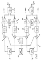
- Each DRFM 1 or 3 is arranged to obtain digital values of the instantaneous phase 0 ⁇ 1(t) or 0 ⁇ 2(t) measured at any particular time t of one of two equal frequency input signals X1 and X2 whose phase difference it is required to determine.
- the input signals X1, X2 are each split equally between two channels by respective signal splitters 5, 7 within the two DRFMs 1, 3.
- the split signals in the first channel of each DRFM 1, 3, the 'inphase' or I channels, are mixed at respective mixers 9, 11 with a sinusoidal signal from a local oscillator 13 common to the two DRFMs 1, 3.
- the split signals in the second channel of each DRFM, the 'quadrature' or Q channels are mixed at respective mixers 15, 17 by the same local oscillator signal after it has been phase shifted by 90 degrees at a phase shifter 19.
- the resultant signals in each pair of I and Q channels are then filtered by respective pairs of low-pass filters 21, 23 and 25, 27 to remove the upper sideband produced by the mixing process, and digitised by respective pairs of analogue/digital converters 29, 31 and 33, 35.
- the four channels are matched such that the digitisation in all four channels occurs simultaneously, the four analogue/digital converters 29, 31, 33, 35 all being clocked by a common sampling clock 37.
- the resultant digital numbers in each channel describe the I and Q components of a signal of carrier frequency equal to the difference between the signal generated by the local oscillator 13 and the frequency of the input signals X1 and X2, where the input signals are sinusoidal, or the carrier frequency of the input signals where the input signals are modulated sinusoids.
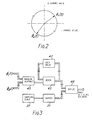
- the phases 0 ⁇ 1(t) and 0 ⁇ 2(t) of the signals may be represented graphically, as illustrated in Figure 2, as vectors rotating in a circle. The amplitudes of the signals are given by the magnitudes of these vectors, whilst the phases 0 ⁇ 1(t) and 0 ⁇ 2(t) are equal to the arc tangent of the ratio of the signals in the respective Q and I channels.
- the values of 0 ⁇ 1(n) and 0 ⁇ 2(n) are derived from the I and Q digital numbers using look-up tables 39, 41.
- a set of values of 0 ⁇ 1(i) and 0 ⁇ 2(i) are thus produced by the DRFMs 1, 3 where i defines equal time intervals 0, 1, 2, 3 ----- (N-1), N being the number of samples taken.
- the required phase difference calculation is carried out by the arithmetic circuit and averaging circuit shown in Figure 3.
- the values of 0 ⁇ 1(i) and 0 ⁇ 2(i) are sequentially input into an arithmetic circuit, such as a modular subtract unit 43, which is arranged to give a value of phase difference 0 ⁇ 1(i) - 0 ⁇ 2(i) between minus 180 degrees and plus 180 degrees using modular arithmetic.
- an arithmetic circuit such as a modular subtract unit 43, which is arranged to give a value of phase difference 0 ⁇ 1(i) - 0 ⁇ 2(i) between minus 180 degrees and plus 180 degrees using modular arithmetic.
- the assumption is made that the phase difference between successive phase measurements takes place in the same direction for each pair of values 0 ⁇ 1(i) and 0 ⁇ 2(i), i.e. clockwise as shown in the graphical representation of Figure 2, or alternatively anticlockwise.
- the output of the modular subtract unit 43 is fed into an averaging or accumulator circuit comprising an adder 45 and a unit delay 47 arranged in a feedback loop to produce a value of the quantity
- This value is fed into a divide circuit 49 together with a value of N produced by a counter 51 addressed by the sampling clock 37 used to clock the analogue to digital converters 29, 31, 33 and 35 of the DRFMs 1 and 3.
- An estimate of the phase difference between the input signals X1, X2 is thus provided at the output of the divide circuit 49.
- an estimate of the phase difference may be obtained from a single sample, such that the estimate is available in real time.
- the apparatus described is designed for very high speed operation. Only the simple operations of subtraction, addition and delay takes place at the sampling clock rate, the division operation only being necessary each time the phase difference estimate is updated, which may be at any desired sub-multiple of the sampling clock rate.
- the apparatus described herebefore has been designed to give the capability of high accuracy measurements. To enable even higher speed operation however it may be expedient to replace the converters 29,31,35,37 and look up tables 39, 41 by four comparators, 51,53,55,57 one in respect of each channel of the two DRFMs 1,3 as shown in Figure 4.
- the comparators 51,53,55,57 are arranged to detect the polarity of their input signal, and give a 1 or 0 output as a result.
- the DRFMs 1, 3 are then only capable of distinguishing the four phase states representing the four I-Q quadrants in the graphical representation of Figure 2, with all amplitude information being lost.
- the dynamic range of such a system is in principle, infinite.
- the phase difference between two copies of a microsecond pulse in the frequency range 2.5 GHz to 3.5 GHz may be measured with an r.m.s. error of 1.6 degrees. If these signals were from a two element array with a half wavelength separation an on-axis directional accuracy of approximately 0.5 degrees may be achieved in the determination of the angle of arrival of an incoming microwave signal.
- apparatus in accordance with the invention may be designed in which an array of three or more quadrature sampling systems, all operating from a common local oscillator, enable the phase differences between pairs of signals arriving at a selection from corresponding array of three or more array elements.
Landscapes
- Physics & Mathematics (AREA)
- General Physics & Mathematics (AREA)
- Measuring Phase Differences (AREA)
- Radar Systems Or Details Thereof (AREA)
Applications Claiming Priority (2)
| Application Number | Priority Date | Filing Date | Title |
|---|---|---|---|
| GB898901054A GB8901054D0 (en) | 1989-01-18 | 1989-01-18 | Phase difference measurement |
| GB8901054 | 1989-01-18 |
Publications (2)
| Publication Number | Publication Date |
|---|---|
| EP0379321A2 true EP0379321A2 (fr) | 1990-07-25 |
| EP0379321A3 EP0379321A3 (fr) | 1991-07-03 |
Family
ID=10650205
Family Applications (1)
| Application Number | Title | Priority Date | Filing Date |
|---|---|---|---|
| EP19900300399 Withdrawn EP0379321A3 (fr) | 1989-01-18 | 1990-01-15 | Mesure de différence de phase |
Country Status (2)
| Country | Link |
|---|---|
| EP (1) | EP0379321A3 (fr) |
| GB (1) | GB8901054D0 (fr) |
Cited By (4)
| Publication number | Priority date | Publication date | Assignee | Title |
|---|---|---|---|---|
| US6154021A (en) * | 1997-12-23 | 2000-11-28 | Telefonaktiebolaget Lm Ericsson (Publ) | Method and arrangement for detecting phase difference |
| RU2273859C1 (ru) * | 2004-07-07 | 2006-04-10 | Балтийская государственная академия рыбопромыслового флота | Корреляционный измеритель флуктуаций |
| RU2339959C2 (ru) * | 2006-11-13 | 2008-11-27 | Балтийская государственная академия рыбопромыслового флота | Корреляционный измеритель флуктуаций |
| RU2626332C1 (ru) * | 2016-07-27 | 2017-07-26 | Негосударственное (частное) образовательное учреждение высшего профессионального образования "Институт радиоэлектроники, сервиса и диагностики" | Способ демодуляции сигнала |
Family Cites Families (4)
| Publication number | Priority date | Publication date | Assignee | Title |
|---|---|---|---|---|
| FR2230118B1 (fr) * | 1973-05-16 | 1976-04-23 | Thomson Csf | |
| FR2514901A1 (fr) * | 1981-10-15 | 1983-04-22 | Onera (Off Nat Aerospatiale) | Procede et dispositif pour comparer l'amplitude et la phase instantanees de deux signaux electriques sinusoidaux de meme frequence et application a la formation d'image par radar |
| US4675614A (en) * | 1982-10-20 | 1987-06-23 | Rockwell International Corporation | Phase difference measurement system |
| US4743905A (en) * | 1985-08-16 | 1988-05-10 | Westinghouse Electric Corp. | Electronic counter measure system utilizing a digital RF memory |
-
1989
- 1989-01-18 GB GB898901054A patent/GB8901054D0/en active Pending
-
1990
- 1990-01-15 EP EP19900300399 patent/EP0379321A3/fr not_active Withdrawn
Cited By (4)
| Publication number | Priority date | Publication date | Assignee | Title |
|---|---|---|---|---|
| US6154021A (en) * | 1997-12-23 | 2000-11-28 | Telefonaktiebolaget Lm Ericsson (Publ) | Method and arrangement for detecting phase difference |
| RU2273859C1 (ru) * | 2004-07-07 | 2006-04-10 | Балтийская государственная академия рыбопромыслового флота | Корреляционный измеритель флуктуаций |
| RU2339959C2 (ru) * | 2006-11-13 | 2008-11-27 | Балтийская государственная академия рыбопромыслового флота | Корреляционный измеритель флуктуаций |
| RU2626332C1 (ru) * | 2016-07-27 | 2017-07-26 | Негосударственное (частное) образовательное учреждение высшего профессионального образования "Институт радиоэлектроники, сервиса и диагностики" | Способ демодуляции сигнала |
Also Published As
| Publication number | Publication date |
|---|---|
| EP0379321A3 (fr) | 1991-07-03 |
| GB8901054D0 (en) | 1989-07-05 |
Similar Documents
| Publication | Publication Date | Title |
|---|---|---|
| US4719469A (en) | Direction-determining system | |
| US9864045B2 (en) | Radar receivers | |
| EP0373802B1 (fr) | Mesure de fréquence | |
| US4675614A (en) | Phase difference measurement system | |
| US3609555A (en) | Digital fm receiver | |
| US5323103A (en) | Frequency measurement receiver with means to resolve two folding frequencies of complex signals | |
| US4761795A (en) | Receiver for bandspread signals | |
| US5079556A (en) | Coherent pulse radar system | |
| EP2717068A1 (fr) | Améliorations apportées à et associées à des récepteurs de radar | |
| US4635060A (en) | Coherent-on-receive radar with prephase correction circuit | |
| RU2518428C2 (ru) | Фазовый способ пеленгации и фазовый пеленгатор для его осуществления | |
| US4024540A (en) | Continuous wave FM tone ranging radar with predetection averaging | |
| CA1210838A (fr) | Radar a impulsions | |
| EP0429948B1 (fr) | Démodulateur pour un signal modulé en phase et récepteur de radio avec un tel démodulateur | |
| US6738435B1 (en) | Matched-filter frequency-shift-keyed receiver using degenerate digital signal processing techniques | |
| EP4158371B1 (fr) | Système et procédés de radiogoniométrie | |
| US3327219A (en) | Detector circuits for directly strobing radio frequency signals | |
| US4982165A (en) | Set-on oscillator | |
| US4144491A (en) | Frequency measuring apparatus | |
| RU2108595C1 (ru) | Одноканальная моноимпульсная радиолокационная система определения направления на цель | |
| KR101358904B1 (ko) | 진폭 변조 레이더, 진폭 변조 레이더의 거리측정오차 저감 장치 및 방법 | |
| EP0379321A3 (fr) | Mesure de différence de phase | |
| RU2099732C1 (ru) | Пеленгатор | |
| RU2176399C1 (ru) | Одноканальная моноимпульсная радиолокационная система определения направления на цель | |
| RU171482U1 (ru) | Комбинированный пеленгатор |
Legal Events
| Date | Code | Title | Description |
|---|---|---|---|
| PUAI | Public reference made under article 153(3) epc to a published international application that has entered the european phase |
Free format text: ORIGINAL CODE: 0009012 |
|
| AK | Designated contracting states |
Kind code of ref document: A2 Designated state(s): AT BE CH DE DK ES FR GB GR IT LI LU NL SE |
|
| PUAL | Search report despatched |
Free format text: ORIGINAL CODE: 0009013 |
|
| AK | Designated contracting states |
Kind code of ref document: A3 Designated state(s): AT BE CH DE DK ES FR GB GR IT LI LU NL SE |
|
| 17P | Request for examination filed |
Effective date: 19911220 |
|
| STAA | Information on the status of an ep patent application or granted ep patent |
Free format text: STATUS: THE APPLICATION HAS BEEN WITHDRAWN |
|
| 18W | Application withdrawn |
Withdrawal date: 19921020 |