EP0379638A1 - Appareil de réception et de distribution de billets de banque et procédé pour son exploitation - Google Patents
Appareil de réception et de distribution de billets de banque et procédé pour son exploitation Download PDFInfo
- Publication number
- EP0379638A1 EP0379638A1 EP89116251A EP89116251A EP0379638A1 EP 0379638 A1 EP0379638 A1 EP 0379638A1 EP 89116251 A EP89116251 A EP 89116251A EP 89116251 A EP89116251 A EP 89116251A EP 0379638 A1 EP0379638 A1 EP 0379638A1
- Authority
- EP
- European Patent Office
- Prior art keywords
- banknote
- banknotes
- switch
- delivery
- conveyor
- Prior art date
- Legal status (The legal status is an assumption and is not a legal conclusion. Google has not performed a legal analysis and makes no representation as to the accuracy of the status listed.)
- Granted
Links
- 238000000034 method Methods 0.000 title claims description 11
- 238000012360 testing method Methods 0.000 claims description 28
- 238000000151 deposition Methods 0.000 claims description 6
- 230000008569 process Effects 0.000 claims description 3
- 239000000463 material Substances 0.000 abstract description 3
- 230000032258 transport Effects 0.000 description 22
- 230000007246 mechanism Effects 0.000 description 5
- 230000008901 benefit Effects 0.000 description 4
- 230000003287 optical effect Effects 0.000 description 3
- 230000008859 change Effects 0.000 description 2
- 238000005352 clarification Methods 0.000 description 1
- 238000010586 diagram Methods 0.000 description 1
- 238000005516 engineering process Methods 0.000 description 1
- 230000006870 function Effects 0.000 description 1
- 239000000976 ink Substances 0.000 description 1
- 238000005259 measurement Methods 0.000 description 1
- 238000012544 monitoring process Methods 0.000 description 1
- 238000004904 shortening Methods 0.000 description 1
Images
Classifications
-
- G—PHYSICS
- G07—CHECKING-DEVICES
- G07D—HANDLING OF COINS OR VALUABLE PAPERS, e.g. TESTING, SORTING BY DENOMINATIONS, COUNTING, DISPENSING, CHANGING OR DEPOSITING
- G07D11/00—Devices accepting coins; Devices accepting, dispensing, sorting or counting valuable papers
- G07D11/0087—Banknote changing devices
-
- G—PHYSICS
- G07—CHECKING-DEVICES
- G07D—HANDLING OF COINS OR VALUABLE PAPERS, e.g. TESTING, SORTING BY DENOMINATIONS, COUNTING, DISPENSING, CHANGING OR DEPOSITING
- G07D11/00—Devices accepting coins; Devices accepting, dispensing, sorting or counting valuable papers
- G07D11/10—Mechanical details
- G07D11/12—Containers for valuable papers
-
- G—PHYSICS
- G07—CHECKING-DEVICES
- G07D—HANDLING OF COINS OR VALUABLE PAPERS, e.g. TESTING, SORTING BY DENOMINATIONS, COUNTING, DISPENSING, CHANGING OR DEPOSITING
- G07D11/00—Devices accepting coins; Devices accepting, dispensing, sorting or counting valuable papers
- G07D11/20—Controlling or monitoring the operation of devices; Data handling
- G07D11/24—Managing the inventory of valuable papers
- G07D11/25—Relocation of valuable papers within devices
-
- G—PHYSICS
- G07—CHECKING-DEVICES
- G07D—HANDLING OF COINS OR VALUABLE PAPERS, e.g. TESTING, SORTING BY DENOMINATIONS, COUNTING, DISPENSING, CHANGING OR DEPOSITING
- G07D11/00—Devices accepting coins; Devices accepting, dispensing, sorting or counting valuable papers
- G07D11/20—Controlling or monitoring the operation of devices; Data handling
- G07D11/30—Tracking or tracing valuable papers or cassettes
Definitions
- the invention relates to a device for accepting and delivering banknotes of the type mentioned in the preamble of claim 1.
- Such devices for accepting and delivering banknotes are advantageously used in service machines of all kinds, in particular from the field of banking and exchange offices.
- a device for accepting and delivering banknotes of the type mentioned in the preamble of claim 1 is known from DE-PS 35 19 607 and has a predetermined number of storage containers for banknotes, each storage container containing only banknotes of a single value level.
- the banknotes are only checked with a tester when they are accepted. When dispensing, the banknotes are removed from the corresponding storage containers, bundled in a stacking wheel and dispensed to a user of the device in a bundle.
- a device for accepting and delivering banknotes has a single test device for the acceptance and delivery control of the banknotes, and it has separate cash registers for the acceptance and delivery of banknotes.
- the dispenser comprises a predetermined number of storage containers, each of which contains only banknotes of a single value level.
- a test device is known from US Pat. No. 4,319,137 which determines the authenticity and the orientation of a banknote by means of optical scanning of the printed image.
- the banknote in the reading plane of the testing device only has to be oriented according to the outer shape, a certain lateral offset being electronically compensated for.
- the result of the scan is compared to patterns from a predetermined set of value levels.
- the banknotes are transported by means of endless belts.
- CH application 00 057 / 89-9 describes a device for turning and rotating banknotes in order to bring them into a predetermined orientation for stacking.
- the invention has for its object to provide a device that automatically takes banknotes of different value levels and dimensions, controls and stores or delivers them to a user, and to specify a method for their operation.
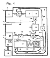
- Fig. 1, 1 means a device for the machine acceptance and delivery of banknotes 2 of different value levels (different denominations of at least one currency), 3 an input opening, 4 a delivery opening, 5 a return tray, 6 a separator, 7 a straightening section, 8 a test device , 9 a first cash register, 10 a second cash register and 11 a turning device.
- a control device 12 is connected by means of lines (not shown here for the sake of illustration) to devices of the device 1, for example to the test device 8, to a banknote store described below, to a first and a second checkout switch 13 and 14, with a delivery switch 15 and with a return switch 16.
- Each switch 13 to 16 has a drive device influenced by the control device 12, e.g. B. an electric motor, an electric magnet, etc., which changes the path of the banknote 2 in each of the switches 13 to 16 from the entrance to one of the two branches.
- the control device 12 selects one of the predetermined routes for the banknote 2 as a function of the signals and information it receives, and for this purpose brings the routes of the switches 13 to 16 into a predetermined position.
- Sensors (not shown here) of the control device 12 are used to monitor sections of the route and to control drive motors (not shown here) of a transport system of the device 1.
- the drive motors are switched on or off by the control 12 as required and are in normal operation except in the turning device 11 the direction of rotation cannot be reversed.
- the control device 12 also exchanges information via a two-way data line 17 with further apparatuses 18, which are represented symbolically with a single rectangle. Some of the apparatuses 18 are either set up separately or are also housed in the same housing as the device 1.
- the transport system of the device 1 comprises a first conveyor belt 19, a second conveyor belt 20, a conveyor section 21, a transport section 22, a belt conveyor 23, a conveyor 24, a connecting section 25, a delivery section 26, a conveyor belt 27 and a return section 28 Because of the clarity of the drawing, they are only indicated with a broad line. Arrows parallel to these lines indicate where necessary the direction of transport for clarification.
- the transport system also includes switches 13 to 16 and three junctions 29 to 31.
- the aforementioned banknote store contains the banknotes 2 of all predetermined value levels which have been accepted by the device 1 and can be called up for delivery.
- it is composed of the two cash registers 9 and 10, the cash register switches 13 and 14, the second conveyor belt 20, the belt conveyor 23, the connecting line 25 and the third junction 31.
- Each till 9 or 10 has a till entrance 32, a till head 33 and the till switch 13 or 14 at the exit.
- a mechanism (not shown) in each checkout head 33 places the banknote 2 arriving through the checkout entrance 32 on a checkout stack 34.
- a spring presses the cash register stack 34 against the mechanism in the cash register head 33 so that it can pick up the uppermost bank note 2 from the cash register stack 34 and insert it into the entrance of the cash register switch 13 or 14. Only in the case of the second cash register 10 shown schematically in section is the cash register head 33 and the cash register stack 34 provided with the reference number.
- the transport system consists of an arrangement of endless, parallel belts, which are guided over rollers, cylinders, guide plates, the drive motors and other elements known from conveyor technology.
- the cylinders and rollers all rotate about axes that are, for example, perpendicular to the plane of the drawing in FIGS. 1 to 3.
- the transport system conveys sheet-like goods having dimensions from a predetermined range, such as. B. banknotes 2 different value levels.
- the material clamped between pairs of belts or between belts and a cylinder is fed from the input opening 3 via the test device 8 to an input of the banknote store, from an outlet of the banknote store via the test device 8 to the delivery opening 4, from the test device 8 to the return tray 5 or from the exit of the banknote store transported to its entrance.
- the conveyor section 21 leads from the separator 6, which is arranged directly behind the input opening 3, through the first junction 29 and the straightening section 7 to the test device 8.
- An output of the test device 8 opens into the input of the return switch 16.
- the transport path 22 connects a branch of the return switch 16 via the turning device 11 to the one input of the second junction 30, while a second branch of the return switch 16 leads via the return path 28 to the return tray 5 .
- a branch of each checkout gate 13 or 14 of the one checkout 9 or 10 is connected to the checkout entrance 32 of the other checkout 10 or 9 by means of the conveyor belt 20 or by means of the belts 19 and 27.
- the belt conveyor 23 and the connecting section 25 form the other two branches of the checkouts 13 and 14. They lead through the two entrances into the third mouth 31 to the conveyor 24. It extends from the exit of the third mouth 31 to an entrance of the first mouth 29
- the first junction 29 enables the banknotes 2 to be introduced from the conveyor 24 into the conveyor section 21, which transports the sheet-like material through the straightening section 7 to the checking device 8.
- the first conveyor track 19 leads through the second opening 30, where the transport route 22 opens into the first conveyor track 19 in the direction of the first cash register 9.
- the end of the first conveyor track 19 forms the delivery diverter 15, one branch of which opens as a conveyor belt 27 into the cash register entrance 32 of the first cash register 9 and the other branch, referred to as the delivery section 26, is connected to the delivery opening 4.
- a user of the device 1 removes z. B. a writing board, which types of banknotes 2 the device 1 recognizes. The user inserts one or more of these banknotes 2 into the return tray 5, which only need to be aligned with the outer shape.
- the banknotes 2 may be wildly mixed and, for example, comprise different value levels and / or issues from different banknotes.
- the device 1 is therefore used as a note changer z. B. in border areas or in international airports and train stations, where notes from other countries are often in circulation.
- the separator 6 Upon a command from the control device 12, the separator 6 detects, for example, the lowest banknote 2 in the input opening 3 and introduces it into the conveyor path 21.
- the bank note 2 reaches the straightening section 7 via the first junction 29.
- the straightening section 7, for example, aligns the long sides of the bank note 2 exactly parallel to the conveying direction of the transport section 21 and forwards the aligned bank note 2 to the checking device 8.
- the separator 6 also introduces this into the conveyor line 21.
- the checking device 8 optically and / or magnetically scans a printed image on at least one side of the bank note 2.
- the recorded pattern is electronically compared with a predetermined set of stored images of the banknotes 2 to be accepted, the checking device 8 determining the value unit, the type of banknote 2 and its orientation.
- Damaged, unidentifiable or incorrect banknotes 2 as well as value levels not belonging to the predetermined set are classified as unidentifiable goods like unprinted paper of suitable size.
- the length and the width of the bank note 2 are also advantageously determined, since this information severely limits the number of value levels to be recognized by the device 1 and belonging to the predetermined set and thus accelerates the determination of the type of bank note.
- a further advantageous shortening of the test time for a bank note 2 is achieved if the test device 8, which scans the bank note 2 using both methods, decides on the basis of these measurements whether only the result of the optical or magnetic scanning is evaluated.
- test device 8 monitors the sheet thickness of the transported goods, which is measured, for example, mechanically or by means of an optical determination of the transparency of the bank note 2. Monitoring the sheet thickness prevents two or more banknotes 2 lying on one another from being accepted.
- Each test result is transmitted to the control device 12 in a value signal.
- the value signal for the goods determines the route in the transport system of the device 1 and the destination.
- the non-identifiable goods are passed via the delivery switch 16 into the return section 28, which transports them into the return tray 5.
- the control device 12 credits the user with a credit corresponding to the value of the accepted banknote 2. For example, this credit can be displayed using one of the apparatuses 18.
- the control device 12 directs this bank note 2 into the transport path 22 by means of the return switch 16. Under the control of the control device 12, the turning device 11 brings the bank note 2 into the predetermined position for storage. At the end of the transport route 22, the banknote 2 is introduced into the first conveyor belt 19 by means of the second junction 30 and from there is conveyed from there by means of the delivery diverter 15 via the conveyor belt 27 through the till entrance 32 into the till head 33 of the first till 9. The mechanism in the cash register head 33 places the bank note 2 on top of the cash stack 34.
- control device 12 decides on the further procedure in accordance with the instructions received via the two-way data line 17.
- the device 1 can use one of the apparatuses 18 to give the user a receipt for paid money and the amount paid in according to the display credit his account, the number of which has been entered on a keyboard (not shown here) of one of the devices 18.
- the user can also use the device 1 to withdraw an amount from his account or exchange the banknotes 2 entered through the input opening 3 for others.
- the device 1 for payment can receive banknotes 2, initiate the service and deliver any note portion of the change.
- the device 1 is connected to a further apparatus 18, which is designed as a coin dispenser and which transfers the remaining portion of the calculated change to the user.
- the mechanism in the cash register head 33 of the second cash register 10 inserts the uppermost bank note 2 of the cash register stack 34 into the cash register switch 14.
- This bank note 2 is fed to the testing device 8 via the connecting section 25 and the conveyor 24. If the bank note 2 has a value level intended for delivery, the switches 16 and 15 guide the bank note 2 into the delivery path 26 when it is removed from the test device 8. On the other hand, if the bank note 2 does not belong to any of these value levels intended for delivery, the bank note becomes 2 returned to the first cash register 9 by means of the switches 16 and 15. This process of stacking is continued until all the value stages provided for the delivery have been introduced into the delivery section 26.
- the advantage of this stacking method is shown in a simple and inexpensive embodiment of the device 1, since only a single banknote store is required to store entered banknotes 2 of a predetermined set of value levels and / or to deliver banknotes 2 of predetermined value levels.
- the unsuitable banknote 2 is retrieved from the first cash register 9 and fed to the testing device 8 via the belt conveyor 23 and via the conveyor 24, this banknote 2 becomes the first through the cash register entrance 32 and through the cash register head 33
- the checkout 9 is transported through to the first checkout gate 13 and then fed via the second conveyor belt 20 through the checkout entrance 32 to the second checkout 10, where the banknote 2 is deposited on the checkout stack 34 by the mechanism of the checkout head 33.
- the value signal and a code number which determines the position of the bank note in the bank note memory with respect to the other bank notes 2 of the cash stack 34 are advantageously written into or deleted in a memory part 35 of the control device 12 , as well as the code numbers for all banknotes that remain in the banknote storage.
- the control device 12 searches the storage part 35 and, based on the registered sequence of the value levels, determines from which till 9 or 10 the banknotes are taken.
- the uppermost banknote 2 on the cash register stack 34 of the cash register 9 or 10 selected by the control device 12 is unsuitable, then this banknote 2 is returned directly to the cash register stack 34 in the other cash register via the conveyor belt 20 or via the belts 19 and 27 10 or 9 filed. If necessary, after a few repetitions of this process, a bank note 2 predetermined for delivery is exposed as the topmost of the cash stack 34, which is fed to the checking device 8. On the other hand, the impossibility of the desired transaction can also be displayed to the user if the cash registers 9 and 10 contain no or too little of the required value levels of the desired bank notes 2.
- the banknote store has a capacity of a few thousand banknotes 2, which corresponds to the maximum size of a single cash stack 34. In an extreme case, after the entire stack of banknotes 2 has been stacked to expose a suitable value level, the entire contents of the banknote store can be contained in a single cash stack 34.
- the control device 12 receives for example, the command from one of the apparatuses 18 to pay out a predetermined amount.
- the control device 12 advantageously optimizes the dispensing in such a way that as few banknotes 2 as possible have to be dispensed from the cash registers 9 and 10, the dispensing taking place from the cash register 9 or 10, with the least possible banknotes 2 have to be moved from one cash register 9 or 10 to another 10 or 9. It is also conceivable to enter the desired denomination of the amount to be dispensed using the keyboard of the apparatus 18.
- the control device 12 decides whether banknotes 2 have to be moved between the checkouts 9 and 10 in such a way that approximately the same number of banknotes in the two checkouts 9 and 10 2 are included.
- the delivery section 26 therefore ends in a stacker 36. It collects the banknotes 2 arriving and to be issued one after the other and delivers them to the user through the delivery opening 4 in one batch.
- the initial equipping of the banknote store on banknotes 2 is composed of different portions of the value levels.
- the control device 12 advantageously maintains statistics on the number and type of banknotes received and dispensed 2. When the device 1 is checked, it can therefore be determined whether the composition of the cash stack 34 is optimal or whether the proportion of certain value levels in the banknote store has to be increased .
- Another advantage over the prior art is the extension of the time between the checks of the device 1, since the banknotes 2 taken are stored in the banknote store and are available again for dispensing, in particular if the dispensing is in this way It is optimized that the disproportionately represented value levels are given preferentially.
- the return switch 16, the return path 28 and the return tray 5 are missing.
- the unidentified goods may then only be passed from the control device 12 to the delivery opening 4 when banknotes 2 are entered, but not when they are released from the banknote store.
- the turning device 11 is omitted. This simplification is purchased with a higher expenditure of time when issuing notes, since the test device 4 also has to determine the orientation of the bank note 2 during the delivery.
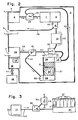
- the device 1 in FIG. 2 is equipped with a simplified transport system and another banknote storage device.
- the transport system of the device 1 comprises only the switches 14 to 16, the conveyor belt 19, the conveyor section 21, the transport section 22, the conveyor 24, the discharge section 26, the conveyor belt 27, the return section 28 and the openings 29 and 30.
- the second checkout switch 13 the third Junction 31 and the sections 20, 23 and 25 of the transport system.
- the banknote store consists of only a single "first in - first out" cash register (FIFO cash register) 37 (FIG. 2).
- the only stack of cash registers 34 in the FIFO cash register 37 is delimited at the cash register entrance 32 from below by a depositing device 38 and on the upper side by a removal device 39.
- the removal device 39 has the only checkout switch 14 on the output side.
- the content of the banknote store, i.e. H. the height of the cash stack 34 determines the distance between the depositing device 38 and the removal device 39.
- the depositing device 38 is pressed, for example, by spring force onto the cash stack 34 against the removal device 39.
- the checkout switch 14 is connected to the conveyor belt 19 via one branch.
- the other branch opens directly into the conveyor 24, which establishes the connection to the test device 8.
- the delivery switch 15 is connected with one branch to the delivery line 26.
- the other branch, the conveyor belt 27, leads to the cash register entrance 32 and has a compensating piece at the cash register end. It adapts to the changing position of the cash register entrance 32, which is determined by the different height of the cash register stack 34.
- a bank note 2 is conveyed into the FIFO cash register 37 via the conveyor belt 27 and is deposited as the lowest in the cash register stack 34 by the depositing device 38.
- the removal device 39 removes the uppermost bank note 2 from the cash stack 34 on a command from the control device 12 and introduces it into the cash switch 14.
- the bank note 2 is sent to the conveyor 24 or via the checkout switch 14 the conveyor belt 19 delivered. If the value level of the uppermost banknote 2 does not match the predetermined value level, the banknotes 2 must be redirected via the conveyor belt 19 and the conveyor belt 27 for stacking until this requirement is met.
- the advantage of the simplified and less expensive banknote storage must be bought with an on average slightly longer delivery time, since the entire contents of the banknote storage may have to be rearranged until the predetermined value level can be released.
- an additional switch 40 is installed at the end of the transport path 22 after the turning device 11 (FIG. 3), one branch of which opens into a container for banknotes 2, which the checking device 8 recognizes, but the device 1 z. B. does not deliver as a foreign currency, and the other branch leads instead of the transport route 22 via the second junction 30 to the conveyor belt 19.
- the container is advantageously designed as a sorting device 41 with a plurality of stacking compartments 42, in order to deposit the banknotes 2 in a predetermined orientation, arranged according to value levels.
- the additional switch 40 and the sorting device 41 are connected to the control device 12 (FIG. 1) via lines (not shown here).
- the control device 12 also decides, for example, on the basis of the content of its storage part 35, at what point in time which banknotes 2 are removed from the banknote store and stored in the predetermined stacking compartments 42 (FIG. 3), so that the banknote store is not clogged by too many banknotes of the same value level.
- the advantages of a device 1 according to FIG. 3 lie in the longer period between the checks, in a permanently optimized content of the banknote store and in the bundles of banknotes 2 which are stored in the stacking compartments 42 with a predetermined orientation.
Landscapes
- Physics & Mathematics (AREA)
- General Physics & Mathematics (AREA)
- Separation, Sorting, Adjustment, Or Bending Of Sheets To Be Conveyed (AREA)
- Financial Or Insurance-Related Operations Such As Payment And Settlement (AREA)
- Pinball Game Machines (AREA)
- Inspection Of Paper Currency And Valuable Securities (AREA)
- Vending Machines For Individual Products (AREA)
- Collation Of Sheets And Webs (AREA)
Applications Claiming Priority (2)
| Application Number | Priority Date | Filing Date | Title |
|---|---|---|---|
| CH23389 | 1989-01-26 | ||
| CH233/89 | 1989-01-26 |
Publications (2)
| Publication Number | Publication Date |
|---|---|
| EP0379638A1 true EP0379638A1 (fr) | 1990-08-01 |
| EP0379638B1 EP0379638B1 (fr) | 1994-11-09 |
Family
ID=4182323
Family Applications (1)
| Application Number | Title | Priority Date | Filing Date |
|---|---|---|---|
| EP89116251A Expired - Lifetime EP0379638B1 (fr) | 1989-01-26 | 1989-09-02 | Appareil de réception et de distribution de billets de banque et procédé pour son exploitation |
Country Status (5)
| Country | Link |
|---|---|
| US (1) | US5076441A (fr) |
| EP (1) | EP0379638B1 (fr) |
| AT (1) | ATE114065T1 (fr) |
| DE (1) | DE58908629D1 (fr) |
| ES (1) | ES2063795T3 (fr) |
Cited By (11)
| Publication number | Priority date | Publication date | Assignee | Title |
|---|---|---|---|---|
| WO1991015000A1 (fr) * | 1990-03-21 | 1991-10-03 | Siemens Nixdorf Informationssysteme Aktiengesellschaft | Installation servant a transporter une liasse de billets ou des objets similaires d'une station collectrice a une station distributrice |
| EP0604880A3 (en) * | 1992-12-30 | 1994-08-24 | Mib Elettronica | Apparatus and method for automatically receiving and dispensing banknotes and valuables. |
| EP0735513A1 (fr) * | 1995-03-31 | 1996-10-02 | DE LA RUE INTER INNOVATION Aktiebolag | Dispositif pour déposer et distribuer des papiers valables |
| EP1517274A2 (fr) | 2003-09-16 | 2005-03-23 | Hitachi, Ltd. | Machine de traitement de billets |
| WO2006063555A1 (fr) * | 2004-12-17 | 2006-06-22 | Wincor Nixdorf International Gmbh | Systeme pour billets de banque |
| WO2009000394A1 (fr) * | 2007-06-22 | 2008-12-31 | Wincor Nixdorf International Gmbh | Distributeur de billets |
| NL2001563C2 (nl) * | 2008-05-07 | 2009-11-11 | Wijngaarden Beheer B V Van | Werkwijze voor verwerken van bankbiljetten en geldtelcentrale. |
| EP2284807A1 (fr) * | 2009-07-28 | 2011-02-16 | Wincor Nixdorf International GmbH | Dispositif de distribution de billets et procédé d'établissement du montant des billets d'au moins un récipient à billets de ce dispositif |
| EP2590148A1 (fr) * | 2011-11-04 | 2013-05-08 | Wincor Nixdorf International GmbH | Dispositif de manutention de documents de valeur avec stockage mixte optimisé |
| EP2602772A3 (fr) * | 2007-06-26 | 2013-12-25 | Innovative Technology Limited | Validateur de billet de banque et/ou carte et appareil de stockage |
| WO2015062891A1 (fr) * | 2013-10-30 | 2015-05-07 | Ci Tech Components Ag | Procédé de manipulation d'éléments en feuilles |
Families Citing this family (92)
| Publication number | Priority date | Publication date | Assignee | Title |
|---|---|---|---|---|
| US5295196A (en) * | 1990-02-05 | 1994-03-15 | Cummins-Allison Corp. | Method and apparatus for currency discrimination and counting |
| US7248731B2 (en) | 1992-05-19 | 2007-07-24 | Cummins-Allison Corp. | Method and apparatus for currency discrimination |
| US6959800B1 (en) | 1995-12-15 | 2005-11-01 | Cummins-Allison Corp. | Method for document processing |
| US6913130B1 (en) | 1996-02-15 | 2005-07-05 | Cummins-Allison Corp. | Method and apparatus for document processing |
| US5247159A (en) * | 1990-11-22 | 1993-09-21 | Kabushiki Kaisha Toshiba | Bill depositing/withdrawing system of the circulation type |
| US6866134B2 (en) | 1992-05-19 | 2005-03-15 | Cummins-Allison Corp. | Method and apparatus for document processing |
| GB2279796B (en) * | 1993-06-28 | 1996-09-25 | Mars Inc | Validating value carriers |
| GB9323709D0 (en) * | 1993-11-15 | 1994-01-05 | Ncr Int Inc | Depository apparatus for envelopes and single sheets |
| US6915893B2 (en) | 2001-04-18 | 2005-07-12 | Cummins-Alliston Corp. | Method and apparatus for discriminating and counting documents |
| DE69520005T2 (de) | 1994-09-16 | 2001-09-06 | Mars, Inc. | Verfahren und vorrichtung für automatische transaktionen mittels mehrerer währungen |
| US6293469B1 (en) | 1994-12-20 | 2001-09-25 | Dh Technology Inc. | Transaction printer |
| US5566807A (en) * | 1995-03-03 | 1996-10-22 | Mars Incorporated | Coin acceptance method and apparatus |
| US6363164B1 (en) | 1996-05-13 | 2002-03-26 | Cummins-Allison Corp. | Automated document processing system using full image scanning |
| US6748101B1 (en) | 1995-05-02 | 2004-06-08 | Cummins-Allison Corp. | Automatic currency processing system |
| US5737418A (en) * | 1995-05-30 | 1998-04-07 | International Game Technology | Encryption of bill validation data |
| US6880692B1 (en) | 1995-12-15 | 2005-04-19 | Cummins-Allison Corp. | Method and apparatus for document processing |
| US8950566B2 (en) | 1996-05-13 | 2015-02-10 | Cummins Allison Corp. | Apparatus, system and method for coin exchange |
| US6661910B2 (en) | 1997-04-14 | 2003-12-09 | Cummins-Allison Corp. | Network for transporting and processing images in real time |
| US8162125B1 (en) | 1996-05-29 | 2012-04-24 | Cummins-Allison Corp. | Apparatus and system for imaging currency bills and financial documents and method for using the same |
| US6860375B2 (en) | 1996-05-29 | 2005-03-01 | Cummins-Allison Corporation | Multiple pocket currency bill processing device and method |
| US7232024B2 (en) | 1996-05-29 | 2007-06-19 | Cunnins-Allison Corp. | Currency processing device |
| US7187795B2 (en) | 2001-09-27 | 2007-03-06 | Cummins-Allison Corp. | Document processing system using full image scanning |
| US7903863B2 (en) | 2001-09-27 | 2011-03-08 | Cummins-Allison Corp. | Currency bill tracking system |
| US20050276458A1 (en) | 2004-05-25 | 2005-12-15 | Cummins-Allison Corp. | Automated document processing system and method using image scanning |
| US7559460B2 (en) | 1996-11-15 | 2009-07-14 | Diebold Incorporated | Automated banking machine |
| US5923413A (en) | 1996-11-15 | 1999-07-13 | Interbold | Universal bank note denominator and validator |
| US7584883B2 (en) | 1996-11-15 | 2009-09-08 | Diebold, Incorporated | Check cashing automated banking machine |
| US7513417B2 (en) | 1996-11-15 | 2009-04-07 | Diebold, Incorporated | Automated banking machine |
| US6573983B1 (en) | 1996-11-15 | 2003-06-03 | Diebold, Incorporated | Apparatus and method for processing bank notes and other documents in an automated banking machine |
| US6607081B2 (en) * | 1996-11-15 | 2003-08-19 | Diebold, Incorporated | Automated transaction machine system |
| US8478020B1 (en) | 1996-11-27 | 2013-07-02 | Cummins-Allison Corp. | Apparatus and system for imaging currency bills and financial documents and method for using the same |
| EP1004089B1 (fr) * | 1996-11-27 | 2007-10-24 | Cummins-Allison Corporation | Systeme de traitement automatise de documents par numerisation de l'image entiere |
| GB9711069D0 (en) * | 1997-05-30 | 1997-07-23 | Ncr Int Inc | Automated teller machines and method of replenishing the same |
| US6109522A (en) * | 1997-11-28 | 2000-08-29 | Diebold, Incorporated | Automated banking machine with self auditing capabilities and system |
| US6003652A (en) * | 1997-12-30 | 1999-12-21 | Fuji Electric Co., Ltd. | Cash dispenser |
| DE19806029C1 (de) * | 1998-02-13 | 1999-09-02 | Siemens Nixdorf Inf Syst | Vorrichtung zur Entnahme von Banknotenbündeln und Bereitstellung an einer Entnahmestelle |
| JP4135238B2 (ja) * | 1998-12-08 | 2008-08-20 | 日立オムロンターミナルソリューションズ株式会社 | 紙幣入出金機 |
| EP1028399A1 (fr) * | 1999-01-15 | 2000-08-16 | NCR International, Inc. | Arrangements de remplissage pour machines bancaires |
| GB2348732B (en) | 1999-04-08 | 2003-08-06 | Mars Inc | Money acceptance apparatus |
| US6588569B1 (en) | 2000-02-11 | 2003-07-08 | Cummins-Allison Corp. | Currency handling system having multiple output receptacles |
| US6460705B1 (en) | 2000-08-09 | 2002-10-08 | Cummins-Allison Corp. | Method of creating identifiable smaller stacks of currency bills within a larger stack of currency bills |
| US6398000B1 (en) | 2000-02-11 | 2002-06-04 | Cummins-Allison Corp. | Currency handling system having multiple output receptacles |
| US6601687B1 (en) | 2000-02-11 | 2003-08-05 | Cummins-Allison Corp. | Currency handling system having multiple output receptacles |
| US6843418B2 (en) | 2002-07-23 | 2005-01-18 | Cummin-Allison Corp. | System and method for processing currency bills and documents bearing barcodes in a document processing device |
| US8701857B2 (en) | 2000-02-11 | 2014-04-22 | Cummins-Allison Corp. | System and method for processing currency bills and tickets |
| GB2360385B (en) * | 2000-03-16 | 2003-11-05 | Mars Inc | Multi-denominational currency store |
| GB2364591A (en) * | 2000-07-07 | 2002-01-30 | Ncr Int Inc | Self service terminal with an escrow unit |
| GB0026022D0 (en) | 2000-10-24 | 2000-12-13 | Rue De Int Ltd | Document store acceptor and recirculator |
| US6742644B1 (en) * | 2000-11-27 | 2004-06-01 | Jcm American Corporation | Note acceptor-dispenser validator |
| US7000828B2 (en) | 2001-04-10 | 2006-02-21 | Cummins-Allison Corp. | Remote automated document processing system |
| US7647275B2 (en) | 2001-07-05 | 2010-01-12 | Cummins-Allison Corp. | Automated payment system and method |
| US8944234B1 (en) | 2001-09-27 | 2015-02-03 | Cummins-Allison Corp. | Apparatus and system for imaging currency bills and financial documents and method for using the same |
| US8437529B1 (en) | 2001-09-27 | 2013-05-07 | Cummins-Allison Corp. | Apparatus and system for imaging currency bills and financial documents and method for using the same |
| US8428332B1 (en) | 2001-09-27 | 2013-04-23 | Cummins-Allison Corp. | Apparatus and system for imaging currency bills and financial documents and method for using the same |
| US8433123B1 (en) | 2001-09-27 | 2013-04-30 | Cummins-Allison Corp. | Apparatus and system for imaging currency bills and financial documents and method for using the same |
| US8437530B1 (en) | 2001-09-27 | 2013-05-07 | Cummins-Allison Corp. | Apparatus and system for imaging currency bills and financial documents and method for using the same |
| JP3754922B2 (ja) * | 2001-12-26 | 2006-03-15 | 日立オムロンターミナルソリューションズ株式会社 | 紙幣取扱装置 |
| US6896118B2 (en) | 2002-01-10 | 2005-05-24 | Cummins-Allison Corp. | Coin redemption system |
| US20050126881A1 (en) * | 2002-02-20 | 2005-06-16 | Iannello Richard J. | Counter/tabletop alignment note feeder with plunger |
| US7551764B2 (en) | 2002-03-25 | 2009-06-23 | Cummins-Allison Corp. | Currency bill and coin processing system |
| US7269279B2 (en) | 2002-03-25 | 2007-09-11 | Cummins-Allison Corp. | Currency bill and coin processing system |
| US7158662B2 (en) | 2002-03-25 | 2007-01-02 | Cummins-Allison Corp. | Currency bill and coin processing system |
| TW506523U (en) * | 2002-03-29 | 2002-10-11 | Hon Hai Prec Ind Co Ltd | Heat pipe |
| GB0213184D0 (en) * | 2002-06-08 | 2002-07-17 | Ncr Int Inc | Self service terminal |
| US8171567B1 (en) | 2002-09-04 | 2012-05-01 | Tracer Detection Technology Corp. | Authentication method and system |
| US8627939B1 (en) | 2002-09-25 | 2014-01-14 | Cummins-Allison Corp. | Apparatus and system for imaging currency bills and financial documents and method for using the same |
| EP1918887A1 (fr) * | 2002-12-27 | 2008-05-07 | MEI, Inc. | Validateur de billet de banque |
| EP1434176A1 (fr) * | 2002-12-27 | 2004-06-30 | Mars, Incorporated | Validateur de billet de banque |
| US7016767B2 (en) | 2003-09-15 | 2006-03-21 | Cummins-Allison Corp. | System and method for processing currency and identification cards in a document processing device |
| SE527837C2 (sv) * | 2004-01-08 | 2006-06-20 | Unjo Ab | Styrsystem för sedelhanterare |
| US7648138B2 (en) * | 2004-09-14 | 2010-01-19 | Hitachi-Omron Terminal Solutions, Corp. | Sheet handling apparatus |
| DE102004061466A1 (de) * | 2004-12-17 | 2006-06-29 | Wincor Nixdorf International Gmbh | Gesichertes Kassensystem zum Aufbewahren von Banknoten und Verfahren zum Steuern eines gesicherten Kassensystems |
| JP4772331B2 (ja) * | 2005-01-20 | 2011-09-14 | 株式会社東芝 | 紙葉類処理装置 |
| US7946406B2 (en) | 2005-11-12 | 2011-05-24 | Cummins-Allison Corp. | Coin processing device having a moveable coin receptacle station |
| CA2539866A1 (fr) * | 2006-03-16 | 2007-09-16 | Crane Canada Co. | Distributrice de billets de banque plate |
| US7980378B2 (en) | 2006-03-23 | 2011-07-19 | Cummins-Allison Corporation | Systems, apparatus, and methods for currency processing control and redemption |
| US7681707B2 (en) * | 2006-04-14 | 2010-03-23 | Tabachnik Bruce M | Drawerless point of sale system and associated methods |
| US7929749B1 (en) | 2006-09-25 | 2011-04-19 | Cummins-Allison Corp. | System and method for saving statistical data of currency bills in a currency processing device |
| US8417017B1 (en) | 2007-03-09 | 2013-04-09 | Cummins-Allison Corp. | Apparatus and system for imaging currency bills and financial documents and method for using the same |
| US8401268B1 (en) | 2007-03-09 | 2013-03-19 | Cummins-Allison Corp. | Optical imaging sensor for a document processing device |
| US8538123B1 (en) | 2007-03-09 | 2013-09-17 | Cummins-Allison Corp. | Apparatus and system for imaging currency bills and financial documents and method for using the same |
| GB2459223B (en) | 2007-03-09 | 2012-07-11 | Cummins Allison Corp | Document imaging and processing system |
| US8256624B2 (en) * | 2009-03-25 | 2012-09-04 | Glory Ltd. | Money handling apparatus and dispensing method thereof |
| US8437532B1 (en) | 2009-04-15 | 2013-05-07 | Cummins-Allison Corp. | Apparatus and system for imaging currency bills and financial documents and method for using the same |
| US8391583B1 (en) | 2009-04-15 | 2013-03-05 | Cummins-Allison Corp. | Apparatus and system for imaging currency bills and financial documents and method for using the same |
| US8929640B1 (en) | 2009-04-15 | 2015-01-06 | Cummins-Allison Corp. | Apparatus and system for imaging currency bills and financial documents and method for using the same |
| GB201100779D0 (en) * | 2011-01-18 | 2011-03-02 | Innovative Technology Ltd | Validation of paid out banknotes |
| JP2013011959A (ja) * | 2011-06-28 | 2013-01-17 | Glory Ltd | 貨幣処理装置 |
| US9141876B1 (en) | 2013-02-22 | 2015-09-22 | Cummins-Allison Corp. | Apparatus and system for processing currency bills and financial documents and method for using the same |
| ITMI20130862A1 (it) * | 2013-05-28 | 2014-11-29 | Razzaboni Cima Spa | Dispositivo per l'introduzione di valori cartacei in contenitori chiudibili, con controllo e memorizzazione dei valori in ingresso nel contenitore |
| JP5807075B2 (ja) * | 2014-01-16 | 2015-11-10 | 日立オムロンターミナルソリューションズ株式会社 | 紙幣入出金装置 |
| EP3540702B1 (fr) * | 2015-06-16 | 2022-12-07 | Diebold Nixdorf Incorporated | Cassette de guichet automatique bancaire et module de cassette |
Citations (6)
| Publication number | Priority date | Publication date | Assignee | Title |
|---|---|---|---|---|
| US4319137A (en) * | 1978-05-23 | 1982-03-09 | Tokyo Shibaura Denki Kabushiki Kaisha | Apparatus for identifying sheet-like printed matters |
| DE3222689A1 (de) * | 1981-06-16 | 1982-12-30 | Laurel Bank Machine Co., Ltd., Tokyo | Maschine zur automatischen annahme und ausgabe von banknoten |
| GB2122010A (en) * | 1982-06-16 | 1984-01-04 | Tokyo Shibaura Electric Co | Automatic depositing/ dispensing apparatus |
| US4473157A (en) * | 1981-01-22 | 1984-09-25 | Tokyo Shibaura Kenki Kabushiki Kaisha | Automatic bank note transaction apparatus |
| DE3519607A1 (de) * | 1984-05-31 | 1985-12-05 | Laurel Bank Machines Co., Ltd., Tokio/Tokyo | Banknoten-ein- und ausgabemechanismus, der mindestens einer ein- und ausgabeoeffnung einer banknoten-annahme- und ausgabemaschine zugeordnet ist |
| GB2197300A (en) * | 1986-10-30 | 1988-05-18 | Laurel Bank Machine Co | Bill receiving and dispensing machine |
Family Cites Families (3)
| Publication number | Priority date | Publication date | Assignee | Title |
|---|---|---|---|---|
| US4479049A (en) * | 1981-01-22 | 1984-10-23 | Tokyo Shibaura Denki Kabushiki Kaisha | Automatic bank note transaction apparatus |
| JPS59149564A (ja) * | 1983-02-15 | 1984-08-27 | Toshiba Corp | 自動取引システム |
| JPS63117832A (ja) * | 1986-11-05 | 1988-05-21 | Hitachi Ltd | 現金自動取引方式 |
-
1989
- 1989-09-02 ES ES89116251T patent/ES2063795T3/es not_active Expired - Lifetime
- 1989-09-02 EP EP89116251A patent/EP0379638B1/fr not_active Expired - Lifetime
- 1989-09-02 AT AT89116251T patent/ATE114065T1/de not_active IP Right Cessation
- 1989-09-02 DE DE58908629T patent/DE58908629D1/de not_active Expired - Fee Related
-
1990
- 1990-01-09 US US07/462,741 patent/US5076441A/en not_active Expired - Lifetime
Patent Citations (6)
| Publication number | Priority date | Publication date | Assignee | Title |
|---|---|---|---|---|
| US4319137A (en) * | 1978-05-23 | 1982-03-09 | Tokyo Shibaura Denki Kabushiki Kaisha | Apparatus for identifying sheet-like printed matters |
| US4473157A (en) * | 1981-01-22 | 1984-09-25 | Tokyo Shibaura Kenki Kabushiki Kaisha | Automatic bank note transaction apparatus |
| DE3222689A1 (de) * | 1981-06-16 | 1982-12-30 | Laurel Bank Machine Co., Ltd., Tokyo | Maschine zur automatischen annahme und ausgabe von banknoten |
| GB2122010A (en) * | 1982-06-16 | 1984-01-04 | Tokyo Shibaura Electric Co | Automatic depositing/ dispensing apparatus |
| DE3519607A1 (de) * | 1984-05-31 | 1985-12-05 | Laurel Bank Machines Co., Ltd., Tokio/Tokyo | Banknoten-ein- und ausgabemechanismus, der mindestens einer ein- und ausgabeoeffnung einer banknoten-annahme- und ausgabemaschine zugeordnet ist |
| GB2197300A (en) * | 1986-10-30 | 1988-05-18 | Laurel Bank Machine Co | Bill receiving and dispensing machine |
Cited By (16)
| Publication number | Priority date | Publication date | Assignee | Title |
|---|---|---|---|---|
| WO1991015000A1 (fr) * | 1990-03-21 | 1991-10-03 | Siemens Nixdorf Informationssysteme Aktiengesellschaft | Installation servant a transporter une liasse de billets ou des objets similaires d'une station collectrice a une station distributrice |
| EP0604880A3 (en) * | 1992-12-30 | 1994-08-24 | Mib Elettronica | Apparatus and method for automatically receiving and dispensing banknotes and valuables. |
| US5488913A (en) * | 1992-12-30 | 1996-02-06 | M.I.B. Elettronica S.R.L. | Apparatus for automatically receiving and dispensing banknotes and valuables |
| EP0735513A1 (fr) * | 1995-03-31 | 1996-10-02 | DE LA RUE INTER INNOVATION Aktiebolag | Dispositif pour déposer et distribuer des papiers valables |
| EP1517274A2 (fr) | 2003-09-16 | 2005-03-23 | Hitachi, Ltd. | Machine de traitement de billets |
| WO2006063555A1 (fr) * | 2004-12-17 | 2006-06-22 | Wincor Nixdorf International Gmbh | Systeme pour billets de banque |
| WO2009000394A1 (fr) * | 2007-06-22 | 2008-12-31 | Wincor Nixdorf International Gmbh | Distributeur de billets |
| US8985297B2 (en) | 2007-06-22 | 2015-03-24 | Wincor Nixdorf International Gmbh | Voucher machine |
| EP2602772A3 (fr) * | 2007-06-26 | 2013-12-25 | Innovative Technology Limited | Validateur de billet de banque et/ou carte et appareil de stockage |
| EP2120219A1 (fr) * | 2008-05-07 | 2009-11-18 | van Wijngaarden Beheer B.V. | Procede de traitement de billets de banque et station de comptage de monnaie |
| NL2001563C2 (nl) * | 2008-05-07 | 2009-11-11 | Wijngaarden Beheer B V Van | Werkwijze voor verwerken van bankbiljetten en geldtelcentrale. |
| EP2284807A1 (fr) * | 2009-07-28 | 2011-02-16 | Wincor Nixdorf International GmbH | Dispositif de distribution de billets et procédé d'établissement du montant des billets d'au moins un récipient à billets de ce dispositif |
| EP2590148A1 (fr) * | 2011-11-04 | 2013-05-08 | Wincor Nixdorf International GmbH | Dispositif de manutention de documents de valeur avec stockage mixte optimisé |
| US8695777B2 (en) | 2011-11-04 | 2014-04-15 | Wincor Nixdorf International Gmbh | Device for handling banknotes with optimized mixed storage |
| WO2015062891A1 (fr) * | 2013-10-30 | 2015-05-07 | Ci Tech Components Ag | Procédé de manipulation d'éléments en feuilles |
| US9926149B2 (en) | 2013-10-30 | 2018-03-27 | Ci Tech Components Ag | Method for handling sheet material |
Also Published As
| Publication number | Publication date |
|---|---|
| US5076441A (en) | 1991-12-31 |
| ATE114065T1 (de) | 1994-11-15 |
| EP0379638B1 (fr) | 1994-11-09 |
| ES2063795T3 (es) | 1995-01-16 |
| DE58908629D1 (de) | 1994-12-15 |
Similar Documents
| Publication | Publication Date | Title |
|---|---|---|
| EP0379638B1 (fr) | Appareil de réception et de distribution de billets de banque et procédé pour son exploitation | |
| DE3216830C2 (de) | Banknoten-Ein/Ausgabe-Vorrichtung | |
| DE60108881T2 (de) | Selbstbedienungsterminal | |
| DE3414519C2 (fr) | ||
| DE69710685T2 (de) | Geldautomaten | |
| DE3325181C2 (fr) | ||
| DE69822880T2 (de) | Bankautomat | |
| DE3440136C2 (fr) | ||
| DE69935111T2 (de) | Maschine zur Einnahme und Ausgabe von Geldscheinen | |
| DE69530868T2 (de) | Verfahren und Apparat zum Unterscheiden und Zählen von Dokumenten | |
| EP1516295B1 (fr) | Dispositif et procede de traitement de billets de banque | |
| EP1195725B1 (fr) | Méthode pour le traitement de feuilles | |
| DE3743386C2 (de) | Maschine zur Annahme und Abgabe von Banknoten | |
| DE3425030A1 (de) | Muenzen-handhabungsvorrichtung | |
| EP2064680A1 (fr) | Dispositif de traitement des billets de banque | |
| DE3744813C2 (de) | Maschine zur Annahme und Ausgabe von Banknoten | |
| DE3321633A1 (de) | Automatische einzahlvorrichtung | |
| DE10049435A1 (de) | Verfahren für die Bearbeitung von Blattgut | |
| DE3321656A1 (de) | Automatische ein/auszahlvorrichtung | |
| DE3321657C2 (fr) | ||
| DE3402703C2 (fr) | ||
| DE10051554A1 (de) | Vorrichtung und Verfahren zur Ablage von Banknoten | |
| EP1423828A2 (fr) | Dispositif de reception d'argent | |
| EP2764502A1 (fr) | Dispositif et procédé de traitement de billets de banque | |
| EP0555531A1 (fr) | Station d'encaissement |
Legal Events
| Date | Code | Title | Description |
|---|---|---|---|
| PUAI | Public reference made under article 153(3) epc to a published international application that has entered the european phase |
Free format text: ORIGINAL CODE: 0009012 |
|
| AK | Designated contracting states |
Kind code of ref document: A1 Designated state(s): AT CH DE ES FR GB IT LI SE |
|
| 17P | Request for examination filed |
Effective date: 19900925 |
|
| RAP1 | Party data changed (applicant data changed or rights of an application transferred) |
Owner name: LANDIS & GYR BUSINESS SUPPORT AG |
|
| 17Q | First examination report despatched |
Effective date: 19930521 |
|
| RAP1 | Party data changed (applicant data changed or rights of an application transferred) |
Owner name: MARS INCORPORATED |
|
| GRAA | (expected) grant |
Free format text: ORIGINAL CODE: 0009210 |
|
| AK | Designated contracting states |
Kind code of ref document: B1 Designated state(s): AT CH DE ES FR GB IT LI SE |
|
| REF | Corresponds to: |
Ref document number: 114065 Country of ref document: AT Date of ref document: 19941115 Kind code of ref document: T |
|
| ITF | It: translation for a ep patent filed | ||
| REF | Corresponds to: |
Ref document number: 58908629 Country of ref document: DE Date of ref document: 19941215 |
|
| REG | Reference to a national code |
Ref country code: ES Ref legal event code: FG2A Ref document number: 2063795 Country of ref document: ES Kind code of ref document: T3 |
|
| ET | Fr: translation filed | ||
| GBT | Gb: translation of ep patent filed (gb section 77(6)(a)/1977) |
Effective date: 19950131 |
|
| PG25 | Lapsed in a contracting state [announced via postgrant information from national office to epo] |
Ref country code: AT Effective date: 19950902 |
|
| PLBE | No opposition filed within time limit |
Free format text: ORIGINAL CODE: 0009261 |
|
| STAA | Information on the status of an ep patent application or granted ep patent |
Free format text: STATUS: NO OPPOSITION FILED WITHIN TIME LIMIT |
|
| 26N | No opposition filed | ||
| PGFP | Annual fee paid to national office [announced via postgrant information from national office to epo] |
Ref country code: SE Payment date: 20000906 Year of fee payment: 12 |
|
| PGFP | Annual fee paid to national office [announced via postgrant information from national office to epo] |
Ref country code: FR Payment date: 20000912 Year of fee payment: 12 |
|
| PGFP | Annual fee paid to national office [announced via postgrant information from national office to epo] |
Ref country code: CH Payment date: 20000922 Year of fee payment: 12 |
|
| PG25 | Lapsed in a contracting state [announced via postgrant information from national office to epo] |
Ref country code: SE Free format text: LAPSE BECAUSE OF NON-PAYMENT OF DUE FEES Effective date: 20010903 |
|
| PG25 | Lapsed in a contracting state [announced via postgrant information from national office to epo] |
Ref country code: LI Free format text: LAPSE BECAUSE OF NON-PAYMENT OF DUE FEES Effective date: 20010930 Ref country code: CH Free format text: LAPSE BECAUSE OF NON-PAYMENT OF DUE FEES Effective date: 20010930 |
|
| REG | Reference to a national code |
Ref country code: GB Ref legal event code: IF02 |
|
| EUG | Se: european patent has lapsed |
Ref document number: 89116251.3 |
|
| REG | Reference to a national code |
Ref country code: CH Ref legal event code: PL |
|
| PG25 | Lapsed in a contracting state [announced via postgrant information from national office to epo] |
Ref country code: FR Free format text: LAPSE BECAUSE OF NON-PAYMENT OF DUE FEES Effective date: 20020531 |
|
| REG | Reference to a national code |
Ref country code: FR Ref legal event code: ST |
|
| REG | Reference to a national code |
Ref country code: GB Ref legal event code: 732E |
|
| REG | Reference to a national code |
Ref country code: GB Ref legal event code: 732E |
|
| PGFP | Annual fee paid to national office [announced via postgrant information from national office to epo] |
Ref country code: DE Payment date: 20070830 Year of fee payment: 19 |
|
| PGFP | Annual fee paid to national office [announced via postgrant information from national office to epo] |
Ref country code: GB Payment date: 20070829 Year of fee payment: 19 |
|
| PGFP | Annual fee paid to national office [announced via postgrant information from national office to epo] |
Ref country code: IT Payment date: 20070926 Year of fee payment: 19 Ref country code: ES Payment date: 20071024 Year of fee payment: 19 |
|
| GBPC | Gb: european patent ceased through non-payment of renewal fee |
Effective date: 20080902 |
|
| PG25 | Lapsed in a contracting state [announced via postgrant information from national office to epo] |
Ref country code: IT Free format text: LAPSE BECAUSE OF NON-PAYMENT OF DUE FEES Effective date: 20080902 Ref country code: DE Free format text: LAPSE BECAUSE OF NON-PAYMENT OF DUE FEES Effective date: 20090401 |
|
| REG | Reference to a national code |
Ref country code: ES Ref legal event code: FD2A Effective date: 20080903 |
|
| PG25 | Lapsed in a contracting state [announced via postgrant information from national office to epo] |
Ref country code: GB Free format text: LAPSE BECAUSE OF NON-PAYMENT OF DUE FEES Effective date: 20080902 |
|
| PG25 | Lapsed in a contracting state [announced via postgrant information from national office to epo] |
Ref country code: ES Free format text: LAPSE BECAUSE OF NON-PAYMENT OF DUE FEES Effective date: 20080903 |