EP0379662A2 - Boîtier de prises - Google Patents
Boîtier de prises Download PDFInfo
- Publication number
- EP0379662A2 EP0379662A2 EP89121193A EP89121193A EP0379662A2 EP 0379662 A2 EP0379662 A2 EP 0379662A2 EP 89121193 A EP89121193 A EP 89121193A EP 89121193 A EP89121193 A EP 89121193A EP 0379662 A2 EP0379662 A2 EP 0379662A2
- Authority
- EP
- European Patent Office
- Prior art keywords
- contact
- socket
- box according
- sockets
- socket box
- Prior art date
- Legal status (The legal status is an assumption and is not a legal conclusion. Google has not performed a legal analysis and makes no representation as to the accuracy of the status listed.)
- Granted
Links
Images
Classifications
-
- H—ELECTRICITY
- H01—ELECTRIC ELEMENTS
- H01R—ELECTRICALLY-CONDUCTIVE CONNECTIONS; STRUCTURAL ASSOCIATIONS OF A PLURALITY OF MUTUALLY-INSULATED ELECTRICAL CONNECTING ELEMENTS; COUPLING DEVICES; CURRENT COLLECTORS
- H01R25/00—Coupling parts adapted for simultaneous co-operation with two or more identical counterparts, e.g. for distributing energy to two or more circuits
- H01R25/003—Coupling parts adapted for simultaneous co-operation with two or more identical counterparts, e.g. for distributing energy to two or more circuits the coupling part being secured only to wires or cables
-
- H—ELECTRICITY
- H01—ELECTRIC ELEMENTS
- H01R—ELECTRICALLY-CONDUCTIVE CONNECTIONS; STRUCTURAL ASSOCIATIONS OF A PLURALITY OF MUTUALLY-INSULATED ELECTRICAL CONNECTING ELEMENTS; COUPLING DEVICES; CURRENT COLLECTORS
- H01R13/00—Details of coupling devices of the kinds covered by groups H01R12/70 or H01R24/00 - H01R33/00
- H01R13/02—Contact members
- H01R13/22—Contacts for co-operating by abutting
- H01R13/24—Contacts for co-operating by abutting resilient; resiliently-mounted
- H01R13/2407—Contacts for co-operating by abutting resilient; resiliently-mounted characterized by the resilient means
- H01R13/2421—Contacts for co-operating by abutting resilient; resiliently-mounted characterized by the resilient means using coil springs
-
- H—ELECTRICITY
- H01—ELECTRIC ELEMENTS
- H01R—ELECTRICALLY-CONDUCTIVE CONNECTIONS; STRUCTURAL ASSOCIATIONS OF A PLURALITY OF MUTUALLY-INSULATED ELECTRICAL CONNECTING ELEMENTS; COUPLING DEVICES; CURRENT COLLECTORS
- H01R13/00—Details of coupling devices of the kinds covered by groups H01R12/70 or H01R24/00 - H01R33/00
- H01R13/648—Protective earth or shield arrangements on coupling devices, e.g. anti-static shielding
- H01R13/655—Protective earth or shield arrangements on coupling devices, e.g. anti-static shielding with earth brace
-
- H—ELECTRICITY
- H01—ELECTRIC ELEMENTS
- H01R—ELECTRICALLY-CONDUCTIVE CONNECTIONS; STRUCTURAL ASSOCIATIONS OF A PLURALITY OF MUTUALLY-INSULATED ELECTRICAL CONNECTING ELEMENTS; COUPLING DEVICES; CURRENT COLLECTORS
- H01R24/00—Two-part coupling devices, or either of their cooperating parts, characterised by their overall structure
- H01R24/20—Coupling parts carrying sockets, clips or analogous contacts and secured only to wire or cable
- H01R24/22—Coupling parts carrying sockets, clips or analogous contacts and secured only to wire or cable with additional earth or shield contacts
-
- H—ELECTRICITY
- H01—ELECTRIC ELEMENTS
- H01R—ELECTRICALLY-CONDUCTIVE CONNECTIONS; STRUCTURAL ASSOCIATIONS OF A PLURALITY OF MUTUALLY-INSULATED ELECTRICAL CONNECTING ELEMENTS; COUPLING DEVICES; CURRENT COLLECTORS
- H01R2103/00—Two poles
-
- H—ELECTRICITY
- H01—ELECTRIC ELEMENTS
- H01R—ELECTRICALLY-CONDUCTIVE CONNECTIONS; STRUCTURAL ASSOCIATIONS OF A PLURALITY OF MUTUALLY-INSULATED ELECTRICAL CONNECTING ELEMENTS; COUPLING DEVICES; CURRENT COLLECTORS
- H01R31/00—Coupling parts supported only by co-operation with counterpart
- H01R31/06—Intermediate parts for linking two coupling parts, e.g. adapter
Definitions
- the invention relates to a socket box with an elongated housing made of plastic, formed from a bottom cover and a detachably connected, hood-shaped upper part, in which at least one, preferably a plurality of sockets and at least one electrically connected connector arranged in a longitudinal end of the housing are arranged are, the socket (s) on the access side being (are) surrounded by a cover frame detachably held on the upper part.
- sockets are fastened in the housing by screws and always show the same position arrangement in the housing.
- the object of the invention is to improve a socket box constructed according to the type mentioned in such a way that an electrical connection of the sockets with one another and with the plug connectors is achieved in a simple and safe and cost-saving manner without wiring, and the sockets are arranged in any desired positions in the housing can.
- the sockets are equipped with contact tabs which are connected to the socket sockets and which can be electrically contacted without wiring using strip-shaped current conductors fixed in the housing.
- the sockets are simply inserted into the housing and are then supported with their contact tabs on the current conductors.
- an average earth contact of each socket closes a contact with a strip-shaped earth conductor, which is also fixed in the housing, thereby ensuring electrical safety.
- the contact lugs are provided diagonally opposite each other on each socket, so that each socket can be arranged in several axially rotated positions in the housing.
- the current conductors formed by flat metal strips and the earth conductor can be produced extremely inexpensively due to the strip shape and are fixed in position in a simple manner by snap-in connection on the bottom cover of the housing.
- the sockets are fixed in their inserted position by a cover frame without a screw connection, the cover frame being held detachably by a snap connection on the upper part.
- the socket box is cheaper to manufacture and shows an extremely simple assembly.
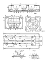
- the socket box (socket strip) has an elongated plastic housing formed from a bottom cover (1) (bottom part) and a hood-shaped upper part (2) detachably connected to it, in which at least one, preferably several, sockets (3) and at least one so that there are provided electrically connected plug connectors (4) arranged in one length end of the housing (i / 2); the socket (s) (3) are surrounded on the access side by a cover frame (5) detachably held on the upper part (2).
- each socket (3) is connected to a middle earth contact (8) and two diagonally opposite one another with their sockets (9) connected contact lugs (10) in axially rotatable positions with the electrical conductors (6) electrically contactable, this electrical connection is made when inserting the sockets (3) only after the contact between the earth conductor (7) and earth contact (8).
- Each socket (3) can be electrically contacted with its two diagonally opposite contact lugs (10) in four operating positions on the two current conductors (6) rotated about its socket axis and is supported on the current conductors (6) with these contact lugs (10).
- the middle grounding contact (8) also automatically closes the contact with the middle grounding conductor (7) in all twisted positions of the socket (3).
- the two contact lugs (10) are directed in opposite directions parallel outwards and downwards and are integrally formed on the sockets (9) or by screws, rivets, soldering 0d. Like., Attached to the sockets (9).
- the two contact tabs (10) each have an outwardly directed web (10a) and a contact angle (10b) pointing downwards and laterally away from the web (10a) (cf. FIGS. 1 and 4).
- the two contact tabs (10) can each be formed by a web which is bent outwards and downwards several times (cf. FIG. 2).
- the two current conductors (6) are formed by flat strips which are rectangular in cross section
- the middle earth conductor (7) is formed by a flat strips which are rectangular or square in cross section, but smaller in width and larger in height than the current conductors (6).
- the current conductors (6) and the middle ground conductor (7) are formed from straight metal strips that take up almost the entire length of the housing and are preferably connected with two end connectors (4).
- the current conductors (6) and the earth conductor (7) are fastened to the base cover (1) in the manner of a push button by means of latching means (11), like clip projections formed on the base cover (1).
- the current conductor (6) and the earth conductor (7) can also be fixed on the bottom cover (1) by other holding means, such as screws, locking strips or the like.
- each socket (3) is preferably formed by a contact pin which is spring-loaded or resilient in the socket (3).
- the earth conductor (8) can be formed by a screw engaging in the earth conductor (7).
- the sockets (3) placed on the current conductors (6) with their contact tabs (10) are fixed in position by the cover frame (5) in the housing (1/2) by holding this cover frame (5) by a snap connection on the upper part (2).
- the cover frame (5) shows a plurality of molded-on locking projections or strips (12) with which it engages behind snap-on edges (13) molded onto the upper part (2).
- the sockets (3) thus only need to be placed on the power and earth rails (6/7) with their contact tabs (10) and the grounding conductor (8), and the cover frame (5) that surrounds the sockets (3) on their access side. fixes the sockets (3) in their inserted position.
- the earthing contact (8) When the sockets (3) are inserted, the earthing contact (8) first comes into contact with the earth conductor (7) and then the two contact lugs (10) come into contact with the current conductors (6).
- a position of the socket (3) with the contact tabs (10) can be seen in full lines and a second rotated position of the socket (3) can be seen in the dash-dotted line.
- ground contact (8) of each socket (3) according to FIGS. 5 and 6, is formed as a cross flag contact with four cross-shaped contact tabs (8a) which are integrally formed on the ground contact socket or fastened to the same.
- This cross-shaped grounding contact (8) enables the socket (3) to be securely connected to the grounding conductor (7) in all twisted positions, by always making two contact tabs (8a) opposite one another with the grounding conductor (7).
- the two or four contact lugs (8a) are designed obliquely and / or curved downwards and outwards in the axial direction of the grounding contact socket.
- the contact tabs (8a) are preferably resilient in themselves.
- the two or four contact tabs (8a) can also be attached to a web or another fastening part of the grounding contact (8).
Landscapes
- Connector Housings Or Holding Contact Members (AREA)
- Connections Arranged To Contact A Plurality Of Conductors (AREA)
- Details Of Connecting Devices For Male And Female Coupling (AREA)
Applications Claiming Priority (2)
| Application Number | Priority Date | Filing Date | Title |
|---|---|---|---|
| DE3902124 | 1989-01-25 | ||
| DE3902124A DE3902124A1 (de) | 1989-01-25 | 1989-01-25 | Steckdosenbox |
Publications (3)
| Publication Number | Publication Date |
|---|---|
| EP0379662A2 true EP0379662A2 (fr) | 1990-08-01 |
| EP0379662A3 EP0379662A3 (fr) | 1991-08-14 |
| EP0379662B1 EP0379662B1 (fr) | 1993-02-17 |
Family
ID=6372751
Family Applications (1)
| Application Number | Title | Priority Date | Filing Date |
|---|---|---|---|
| EP89121193A Expired - Lifetime EP0379662B1 (fr) | 1989-01-25 | 1989-11-16 | Boîtier de prises |
Country Status (2)
| Country | Link |
|---|---|
| EP (1) | EP0379662B1 (fr) |
| DE (2) | DE3902124A1 (fr) |
Cited By (8)
| Publication number | Priority date | Publication date | Assignee | Title |
|---|---|---|---|---|
| EP0495359A1 (fr) * | 1991-01-16 | 1992-07-22 | A. & H. Meyer GmbH Leuchten und Büroelektrik | Boîtier des prises de courant |
| EP0768737A1 (fr) * | 1995-10-16 | 1997-04-16 | Lk A/S | Boîtier de prises |
| ES2142270A1 (es) * | 1998-03-11 | 2000-04-01 | Arrufat Julian Alicia | Conjunto modular para bases de enchufe moviles o fijas. |
| ES2142271A1 (es) * | 1998-03-12 | 2000-04-01 | Arrufat Julian Alicia | Mecanismo modular para bases de enchufe con toma de tierra. |
| BE1013740A3 (nl) * | 2000-10-06 | 2002-07-02 | Camp Frans | Stopcontact. |
| WO2009115457A1 (fr) * | 2008-03-19 | 2009-09-24 | Electrak International Limited | Prises électriques |
| EP1835795A3 (fr) * | 2006-03-17 | 2011-04-27 | Eaton Power Quality Corporation | Ensembles interconnectés de puissance et procédés pour les configurer |
| WO2014195722A1 (fr) * | 2013-06-07 | 2014-12-11 | Foley, Barry | Améliorations dans ou concernant des prises femelles électriques |
Families Citing this family (8)
| Publication number | Priority date | Publication date | Assignee | Title |
|---|---|---|---|---|
| DE4309453C1 (de) * | 1993-03-24 | 1994-09-15 | Modelec Sa | Steckdosenbox |
| EP0618647B1 (fr) * | 1993-04-02 | 1999-08-04 | A. & H. Meyer GmbH Leuchten und Büroelektrik | Boítier des prises de courant |
| DE4312423B4 (de) * | 1993-04-16 | 2012-08-30 | A. & H. Meyer GmbH Leuchten und Büroelektrik | Kontaktschiene für elektrische Installationsgeräte, insbesondere in Steckdosenboxen |
| DE4433144A1 (de) * | 1994-09-16 | 1996-03-21 | Kopp Heinrich Ag | Steckdose mit drehbarem Steckereinschubabschnitt |
| DE29502014U1 (de) * | 1995-02-08 | 1995-04-13 | A. & H. Meyer GmbH Leuchten und Büroelektrik, 32694 Dörentrup | Steckdosenbox |
| DE19508552A1 (de) * | 1995-03-10 | 1996-09-12 | Gerhard Glabischnig | Stecksteckdose |
| DE19932561C2 (de) * | 1999-07-13 | 2003-07-24 | Aloys Mennekes Anlagengmbh & C | Mehrfach-Steckdose |
| DE10328503A1 (de) * | 2003-06-25 | 2005-01-13 | Abb Patent Gmbh | Steckdosenleiste für eine vorgegebene Anzahl von Steckerelementen |
Family Cites Families (7)
| Publication number | Priority date | Publication date | Assignee | Title |
|---|---|---|---|---|
| US2215712A (en) * | 1938-12-12 | 1940-09-24 | Porcelain Products Inc | Electrical convenience outlet |
| NL225680A (fr) * | 1957-08-13 | |||
| DE1257927B (de) * | 1965-04-13 | 1968-01-04 | Hahn & Kolb | Vorrichtung zum Abnehmen von elektrischem Strom an beliebiger Stelle einer Wand |
| DE7232810U (de) * | 1972-09-06 | 1972-12-21 | Kinkeldey-Leuchten A Kinkeldey | Adapter fur Stromabnehmer |
| DE7602708U1 (de) * | 1976-01-31 | 1977-03-03 | Abke, Hermann, 4972 Loehne | NetzanschluBeinheit zur Verteilung elektrischer Energie |
| EP0009151A1 (fr) * | 1978-09-02 | 1980-04-02 | Wilfried Pöllet | Prise de courant de sécurité multiple formée par des bars électriques et son encastrement dans un couvercle de gaîne |
| DE3243728A1 (de) * | 1982-11-26 | 1984-05-30 | Bosch Gmbh Robert | Elektrisches verteilerelement |
-
1989
- 1989-01-25 DE DE3902124A patent/DE3902124A1/de active Granted
- 1989-11-16 DE DE8989121193T patent/DE58903574D1/de not_active Expired - Lifetime
- 1989-11-16 EP EP89121193A patent/EP0379662B1/fr not_active Expired - Lifetime
Cited By (11)
| Publication number | Priority date | Publication date | Assignee | Title |
|---|---|---|---|---|
| EP0495359A1 (fr) * | 1991-01-16 | 1992-07-22 | A. & H. Meyer GmbH Leuchten und Büroelektrik | Boîtier des prises de courant |
| EP0768737A1 (fr) * | 1995-10-16 | 1997-04-16 | Lk A/S | Boîtier de prises |
| ES2142270A1 (es) * | 1998-03-11 | 2000-04-01 | Arrufat Julian Alicia | Conjunto modular para bases de enchufe moviles o fijas. |
| ES2142271A1 (es) * | 1998-03-12 | 2000-04-01 | Arrufat Julian Alicia | Mecanismo modular para bases de enchufe con toma de tierra. |
| BE1013740A3 (nl) * | 2000-10-06 | 2002-07-02 | Camp Frans | Stopcontact. |
| EP1835795A3 (fr) * | 2006-03-17 | 2011-04-27 | Eaton Power Quality Corporation | Ensembles interconnectés de puissance et procédés pour les configurer |
| WO2009115457A1 (fr) * | 2008-03-19 | 2009-09-24 | Electrak International Limited | Prises électriques |
| RU2496195C2 (ru) * | 2008-03-19 | 2013-10-20 | Легранд Электрик Лимитед | Розеточный блок |
| WO2014195722A1 (fr) * | 2013-06-07 | 2014-12-11 | Foley, Barry | Améliorations dans ou concernant des prises femelles électriques |
| US10063051B2 (en) | 2013-06-07 | 2018-08-28 | Barry FOLEY | Electrical sockets |
| GB2516365B (en) * | 2013-06-07 | 2018-09-12 | Barry Foley | Improvements in or relating to electrical sockets |
Also Published As
| Publication number | Publication date |
|---|---|
| EP0379662B1 (fr) | 1993-02-17 |
| DE3902124C2 (fr) | 1992-02-13 |
| DE3902124A1 (de) | 1990-08-02 |
| EP0379662A3 (fr) | 1991-08-14 |
| DE58903574D1 (de) | 1993-03-25 |
Similar Documents
| Publication | Publication Date | Title |
|---|---|---|
| DE69017980T2 (de) | Steckdoseneinheit für ein modulares Energieverteilungssystem für Möbel. | |
| EP0304393B1 (fr) | Dispositif de fixation de blocs de connexion en télécommunication | |
| EP1096606B1 (fr) | Borne de connexion | |
| DE3902124C2 (fr) | ||
| DE4022876C2 (fr) | ||
| EP3480898B1 (fr) | Cadre de retenue modulaire pour connecteurs électriques | |
| DE4113559A1 (de) | Verbinder-einbauanordnung | |
| EP0616401B1 (fr) | Pile de barres omnibus | |
| EP0123872A1 (fr) | Barrière à diode Zéner | |
| EP0148334B1 (fr) | Dispositif pour la fixation d'accessoires sur la paroi d'une armature lumineuse | |
| EP0618647B1 (fr) | Boítier des prises de courant | |
| DE2743033A1 (de) | Vorrichtung zum verhindern falscher elektrischer steckverbindungen | |
| DE3641153C2 (fr) | ||
| DE2835952A1 (de) | Elektrisches versorgungssystem | |
| DE3238483A1 (de) | Sammelschienensystem | |
| DE2712723A1 (de) | Elektrischer verteiler | |
| EP1296431A2 (fr) | Ensemble de barres de distribution | |
| DE19602052B4 (de) | Steckdosenbox | |
| DE3640402C1 (de) | UEberspannungsschutzgeraet | |
| DE2116342A1 (de) | Elektrische Steckverbinder | |
| EP0951104B1 (fr) | Prise, particulièrement un boítier encastrable pour installations électriques | |
| DE9205977U1 (de) | Mehrpoliger Kabelsteckverbinder | |
| DE69904504T2 (de) | Busschienenverbindungsstruktur | |
| DE3332917C2 (fr) | ||
| DE9305056U1 (de) | Steckdosenbox |
Legal Events
| Date | Code | Title | Description |
|---|---|---|---|
| PUAI | Public reference made under article 153(3) epc to a published international application that has entered the european phase |
Free format text: ORIGINAL CODE: 0009012 |
|
| AK | Designated contracting states |
Kind code of ref document: A2 Designated state(s): BE DE FR GB NL |
|
| PUAL | Search report despatched |
Free format text: ORIGINAL CODE: 0009013 |
|
| AK | Designated contracting states |
Kind code of ref document: A3 Designated state(s): BE DE FR GB NL |
|
| 17P | Request for examination filed |
Effective date: 19910727 |
|
| 17Q | First examination report despatched |
Effective date: 19920128 |
|
| GRAA | (expected) grant |
Free format text: ORIGINAL CODE: 0009210 |
|
| AK | Designated contracting states |
Kind code of ref document: B1 Designated state(s): BE DE FR GB NL |
|
| PG25 | Lapsed in a contracting state [announced via postgrant information from national office to epo] |
Ref country code: GB Effective date: 19930217 |
|
| REF | Corresponds to: |
Ref document number: 58903574 Country of ref document: DE Date of ref document: 19930325 |
|
| ET | Fr: translation filed | ||
| GBV | Gb: ep patent (uk) treated as always having been void in accordance with gb section 77(7)/1977 [no translation filed] |
Effective date: 19930217 |
|
| PLBE | No opposition filed within time limit |
Free format text: ORIGINAL CODE: 0009261 |
|
| STAA | Information on the status of an ep patent application or granted ep patent |
Free format text: STATUS: NO OPPOSITION FILED WITHIN TIME LIMIT |
|
| 26N | No opposition filed | ||
| PGFP | Annual fee paid to national office [announced via postgrant information from national office to epo] |
Ref country code: DE Payment date: 20081128 Year of fee payment: 20 Ref country code: NL Payment date: 20081103 Year of fee payment: 20 |
|
| PGFP | Annual fee paid to national office [announced via postgrant information from national office to epo] |
Ref country code: BE Payment date: 20081110 Year of fee payment: 20 |
|
| PGFP | Annual fee paid to national office [announced via postgrant information from national office to epo] |
Ref country code: FR Payment date: 20081112 Year of fee payment: 20 |
|
| BE20 | Be: patent expired |
Owner name: A. & H. *MEYER G.M.B.H. LEUCHTEN UND BUROELEKTRIK Effective date: 20091116 |
|
| NLV7 | Nl: ceased due to reaching the maximum lifetime of a patent |
Effective date: 20091116 |
|
| PG25 | Lapsed in a contracting state [announced via postgrant information from national office to epo] |
Ref country code: NL Free format text: LAPSE BECAUSE OF EXPIRATION OF PROTECTION Effective date: 20091116 |