EP0379664B1 - Collecteur pour machines électriques - Google Patents
Collecteur pour machines électriques Download PDFInfo
- Publication number
- EP0379664B1 EP0379664B1 EP89121438A EP89121438A EP0379664B1 EP 0379664 B1 EP0379664 B1 EP 0379664B1 EP 89121438 A EP89121438 A EP 89121438A EP 89121438 A EP89121438 A EP 89121438A EP 0379664 B1 EP0379664 B1 EP 0379664B1
- Authority
- EP
- European Patent Office
- Prior art keywords
- conductive bar
- free end
- connecting hook
- hook
- insert
- Prior art date
- Legal status (The legal status is an assumption and is not a legal conclusion. Google has not performed a legal analysis and makes no representation as to the accuracy of the status listed.)
- Expired - Lifetime
Links
Images
Classifications
-
- H—ELECTRICITY
- H02—GENERATION; CONVERSION OR DISTRIBUTION OF ELECTRIC POWER
- H02K—DYNAMO-ELECTRIC MACHINES
- H02K13/00—Structural associations of current collectors with motors or generators, e.g. brush mounting plates or connections to windings; Disposition of current collectors in motors or generators; Arrangements for improving commutation
- H02K13/04—Connections between commutator segments and windings
-
- H—ELECTRICITY
- H01—ELECTRIC ELEMENTS
- H01R—ELECTRICALLY-CONDUCTIVE CONNECTIONS; STRUCTURAL ASSOCIATIONS OF A PLURALITY OF MUTUALLY-INSULATED ELECTRICAL CONNECTING ELEMENTS; COUPLING DEVICES; CURRENT COLLECTORS
- H01R39/00—Rotary current collectors, distributors or interrupters
- H01R39/02—Details for dynamo electric machines
- H01R39/32—Connections of conductor to commutator segment
Definitions
- the invention relates to a commutator for electric machines which consists of a plurality of conductive bars which are insulated the one from the other, each conductive bar being provided at one end thereof with a connecting hook-like member, and an electric wire of the respective winding being enclosed in said connecting hook-like member, with the free end of said member being so bent about the electric wire and being so pressed against the surface of the conductive bar that the terminal portion of the free end of the connecting hook-like member bears against the surface of the conductive bar, and the connecting hook-like member surrounds the electric wire, the insulation of the electric wire being eliminated at the portion of its contact with the surface of the hook-like member and/or the said wire being welded to the said connecting hook-like member by means of a heating electric current.
- a commutator of this kind is known from the document GB-A-2 203 291 and by having been manufactured by the applicant.
- the conductive bars are so made that when the free end of a connecting hook-like member comes to be set into contact with the surface of a conductive bar, an electric contact will be produced between the said two members.
- Such an electric contact causes derived leakage currents to be originated when the heating and/or welding electric current is being fed at a connecting hook-like member.
- the said leakage currents considerably reduce the heating efficiency at the contact area between an electric wire and a connecting hook-like member, so that in order to obtain a required performance, the pressure force between a hook-like member and an electric wire needs to be increased. Therefore, also the pressure stress at only one end of a conductive bar will be thus increased.
- the problem on which the invention is founded therefore is to provide a commutator of the type as described in the preamble, in which with the aid of means of a simple and economical construction, an electric wire of a winding can be firmly engaged with the respective conductive bar, by concentrating the effects of the electric heating in the area for the mutual contact of this electric wire and the connecting hook-like member of the associated conductive bar, whereby to avoid the aforementioned drawbacks which are due to a high welding pressure and to the derived leakage currents, and to thus obtain a better electric contact between the wire and the conductive bar, without impairing the commutator.
- the invention solves the problem as set forth above by the feature that at least one or both of the areas for the mutual contact of a conductive bar and the free end of the terminal portion of the connecting hook-like member comprise insulating material so that they are electrically insulated from each other.
- the conductive bar portion for the contact of this portion with the free end of the connecting hook-like member is formed by an insert of an insulating material, particularly of the same insulating material as provided between the individual commutator bars, and the said insert extends over a part, or over the entire width of a bar.
- an insulating material particularly of the same insulating material as provided between the individual commutator bars
- the said insert extends over a part, or over the entire width of a bar.
- air may be provided as insulating matter, or that portion of the conductive bar surface which is meant for its contact with the free end of the connecting hook-like member, may be formed with a hole, a recess, or the like, to be simply left void.
- the insulating material is provided in that portion of a connecting hook-like member free end which is meant for its contact with the conductive bar, and the said material may, for example, form either entirely or partly the terminal portion of the free end of a connecting hook-like member.
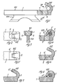
- Figure 1 there is shown a first embodiment of a conductive bar of a commutator for electric machines.
- the commutator (not shown) consists of a plurality of conductive bars arranged in a side-by-side relation and insulated from each other. The assembly of these conductive bars forms a generally cylindrical surface, with each bar constituting an electrically conductive segment, and being in turn electrically connected with an electric wire of a winding.
- the bar 1 shown in Figure 1 consists of a contact rod of an electrically conductive material, generally copper or a suitable alloy, with its contact surface 101 being slightly curved.
- the bar 1 is provided on its side lying opposite to the contact surface 101, with an anchoring extension 201 for incorporating and firmly engaging by a positive coupling the said bar in a supporting mass.
- This supporting mass may be of plastics material and may at the same time form also the electric insulation between the individual conductive bars.
- Each conductive bar 1 is provided at one end thereof with an appendix in form of a connecting hook-like member 2 for the electrical connection of an electric wire 3 of the associated winding.
- This connecting hook-like member 2 is formed of one piece with the conductive bar 1 and is, particularly at its free end 102, of a smaller width than the bar 1 ( Figure 2).
- the inner bending radius of the connecting hook-like member 2 substantially corresponds to the radius of the electric wire 3 which is housed therewithin.
- this latter bar is provided in the area for its contact with the connecting hook-like member 2, with an insert 6 of insulating material.
- the said insert 6 of insulating material is formed by electrically insulating plastics material which fills a respective hole 7 provided in the conductive bar 1 and extending throughout the thickness of the bar.
- the insulating material 6 which fills the hole 7, is so confined that it is substantially flush with the bar 1.
- the insert 6 and the hole 7 have a diameter which is slightly greater than the width of the terminal portion of the free end 102 of the connecting-hook-like member 2.
- the hole 7 may receive any desired type of electrically insulating material, and may be even left void, so as to profit by the electric insulation properties of air. Otherwise, when a supporting mass is used, such as a mass of plastics material or of an electrically insulating material, the said hole 7 may be filled, at the time the conductive bars are being incorporated into the supporting mass, with the same supporting mass which is caused to likely fill also the insulating gaps between the individual bars.
- FIGs 5 and 6 there is shown a second embodiment of the conductive bar.
- the conductive bar 1 and its connecting hook-like member 2 are similar to the embodiment according to Figure 1, and the difference between the two embodiments resides only in the insert of insulating material located in the area for the mutual contact between the terminal portion of the free end 102 of the connecting hook-like member 2 and the surface of the conductive bar 1.
- the insulating insert 6′ located in the area for the mutual contact between the conductive bar 1 and the free end 102 of its hook-like member 2 is actually formed by a layer of electrically insulating material having a smaller thickness than the bar 1, and being received into a respective recess 8 in the conductive bar 1, which is provided in the said area.
- the said insulating insert 6′ extends throughout the width of the conductive bar 1 so as to complete its shape, and is substantially flush with the said bar. Also in this case, the recess 8 may be left void, or the electric insulation may be formed solely by air. Preferably, however, the insert 6′ is suitably formed by the same supporting and insulating mass as for the conductive bars, similarly as disclosed in the former embodiment.
- FIGs 7 and 8 there is shown a third embodiment of the conductive bar according to the invention.
- the insert of insulating material 6 ⁇ forms the terminal portion of the free end 102 of the connecting hook-like member 2, and the said portion is caused to bear against the surface of the conductive bar 1.
- the corner piece which is turned toward the surface of the conductive bar 1 has been cut off from the terminal portion of the free end 102 of the connecting hook-like member 2, and the said cut-off piece has been replaced with an insert 6 ⁇ having a correspondent triangular cross-sectional shape, and being formed by an electrically insulating material.
- the bar according to the invention therefore allows to eliminate in a simple and economical manner any derived leakage currents, and to obtain a concentration of the heating action in the area in which an electric wire 3 of a winding and the connecting hook-like member 2 of the respective conductive bar 1 bear against each other.
- it is possible to make with a lower expenditure of time and energy, a highly conductive electric connection of the commutator to the respective windings and to improve the electric efficiency of the commutator, while avoiding that the same may be impaired during the connection step.
- the construction of the insulating insert may be even limited to the provision of recesses made in the area for the mutual contact between a conductive bar and the terminal portion of the free end of its connecting hook-like member, since the said recesses can be filled with the same supporting mass for the conductive bars, at the time the said bars are being incorporated, without having thus to provide a further operative step in the commutator manufacturing process.
- the invention is not limited to the just described and shown embodiments, and the same may be widely changed and modified, the more so in construction.
- the electrically insulating pieces which are provided in a conductive bar 1 and in its connecting hook-like member 2 may be of any desired shape and size, and may be simultaneously provided in the conductive bar 1 and in the terminal portion of the free end of the connecting hook-like member 2. The whole without departing from the scope of the Claims.
Landscapes
- Engineering & Computer Science (AREA)
- Power Engineering (AREA)
- Motor Or Generator Current Collectors (AREA)
- Dc Machiner (AREA)
- Insulation, Fastening Of Motor, Generator Windings (AREA)
- Paper (AREA)
- Branch Pipes, Bends, And The Like (AREA)
- Electrical Discharge Machining, Electrochemical Machining, And Combined Machining (AREA)
Claims (10)
- Un collecteur pour des machines électriques qui consiste en un ensemble de lames conductrices (1) qui sont mutuellement isolées, chaque lame conductrice comportant à une extrémité un élément de connexion en forme de crochet (2), avec un fil électrique (3) de l'enroulement respectif emprisonné dans cet élément de connexion en forme de crochet, et avec l'extrémité libre (102) de cet élément (2) courbée autour du fil électrique (3) et pressée contre la surface de la lame conductrice (1) de façon que la partie terminale de l'extrémité libre (102) de l'élément de connexion en forme de crochet (2) porte contre la surface de la lame conductrice (1), et que l'élément en forme de crochet (2) entoure le fil électrique (3), l'isolant du fil électrique (3) étant éliminé dans la partie dans laquelle ce fil est en contact avec la surface de l'élément en forme de crochet (2), et/ou le fil (3) étant soudé à l'élément de connexion en forme de crochet (2) au moyen d'un courant électrique de chauffage, caractérisé en ce que l'une au moins des zones de contact mutuel de la lame conductrice (1) et de l'extrémité libre (102) de la partie terminale de l'élément de connexion en forme de crochet (2) consiste en un matériau isolant, de façon que la lame conductrice et l'extrémité libre précitée soient mutuellement isolées au point de vue électrique.
- Le collecteur selon la revendication 1, caractérisé en ce que la partie de la lame conductrice (1) qui est destinée à venir en contact avec l'extrémité libre (102) de l'élément de connexion en forme de crochet (2) est formée par un élément rapporté d'isolation électrique (6, 6').
- Le collecteur selon la revendication 2, caractérisé en ce que l'élément rapporté d'isolation électrique (6, 6') est formé par une matière à l'état solide.
- Le collecteur selon la revendication 3, caractérisé en ce que l'élément rapport d'isolation électrique (6, 6') est formé par une matière d'isolation électrique identique à celle qui est employée entre les lames conductrices individuelles (1) du collecteur.
- Le collecteur selon l'une quelconque ou plusieurs des revendications précédentes, caractérisé en ce que l'élément rapporté d'isolation électrique (6, 6') est logé dans une cavité respective (7, 8) qui est formée dans la surface de la lame conductrice (1), et qui est placée dans la région de cette lame (1) qui est destinée à venir en contact avec la partie terminale de l'extrémité libre (102) de l'élément de contact en forme de crochet (2).
- Le collecteur selon la revendication 5, caractérisé en ce que la cavité qui est destinée à recevoir l'élément rapporté d'isolation électrique (6) est un trou (7) qui s'étend à travers une partie ou la totalité de l'épaisseur de la lame conductrice (1), et qui a un diamètre supérieur à celui de la partie terminale associée de l'extrémité libre (102) de l'élément de connexion en forme de crochet (2).
- Le collecteur selon la revendication 5, caractérisé en ce que la cavité qui est destinée à recevoir l'élément rapporté d' isolation électrique (6') est une cavité ayant une profondeur qui est inférieure à l'épaisseur de la lame conductrice (1), et qui s'étend sur toute la largeur, ou sur une partie de la largeur, de la lame conductrice.
- Le collecteur selon l'une quelconque ou plusieurs des revendications précédentes, caractérisé en ce que l'élément rapporté (6, 6') en une matière isolante s'étend jusqu'aux surfaces qui délimitent la lame conductrice (1), de façon à affleurer pratiquement ces surfaces.
- Le collecteur selon la revendication 1, caractérisé en ce que l'élément rapporté (6'') en une matière isolante est placé dans la partie terminale de l'extrémité libre (102) de l'élément de connexion en forme de crochet (2).
- Le collecteur selon la revendication 9, caractérisé en ce que l'élément rapporté (6'') en une matière isolante forme la pièce de coin de la partie terminale de l'extrémité libre (102) de l'élément de connexion en forme de crochet (2), qui fait face à la lame conductrice (1) et qui s'étend de façon à compléter pratiquement l'extrémité libre précitée (102).
Priority Applications (1)
| Application Number | Priority Date | Filing Date | Title |
|---|---|---|---|
| AT89121438T ATE93102T1 (de) | 1989-01-25 | 1989-11-20 | Kommutator fuer elektrische maschinen. |
Applications Claiming Priority (2)
| Application Number | Priority Date | Filing Date | Title |
|---|---|---|---|
| IT8912412A IT1232463B (it) | 1989-01-25 | 1989-01-25 | Collettore per macchine elettriche |
| IT1241289 | 1989-01-25 |
Publications (2)
| Publication Number | Publication Date |
|---|---|
| EP0379664A1 EP0379664A1 (fr) | 1990-08-01 |
| EP0379664B1 true EP0379664B1 (fr) | 1993-08-11 |
Family
ID=11139859
Family Applications (1)
| Application Number | Title | Priority Date | Filing Date |
|---|---|---|---|
| EP89121438A Expired - Lifetime EP0379664B1 (fr) | 1989-01-25 | 1989-11-20 | Collecteur pour machines électriques |
Country Status (4)
| Country | Link |
|---|---|
| EP (1) | EP0379664B1 (fr) |
| AT (1) | ATE93102T1 (fr) |
| DE (1) | DE68908386T2 (fr) |
| IT (1) | IT1232463B (fr) |
Families Citing this family (3)
| Publication number | Priority date | Publication date | Assignee | Title |
|---|---|---|---|---|
| DE10018301A1 (de) * | 2000-04-13 | 2001-10-25 | Bosch Gmbh Robert | Hakenkommutator |
| DE10042512A1 (de) * | 2000-08-30 | 2002-03-28 | Bosch Gmbh Robert | Hakenkommutator |
| US6958563B2 (en) * | 2003-01-16 | 2005-10-25 | Energy Conversion Systems Holdings, Llc | Riser commutators |
Family Cites Families (2)
| Publication number | Priority date | Publication date | Assignee | Title |
|---|---|---|---|---|
| GB2189352A (en) * | 1986-04-02 | 1987-10-21 | Johnson Electric Ind Mfg | Commutator segment terminal arrangement |
| GB2203291B (en) * | 1987-03-23 | 1991-05-22 | Johnson Electric Ind Mfg | Assembled commutator |
-
1989
- 1989-01-25 IT IT8912412A patent/IT1232463B/it active
- 1989-11-20 EP EP89121438A patent/EP0379664B1/fr not_active Expired - Lifetime
- 1989-11-20 AT AT89121438T patent/ATE93102T1/de not_active IP Right Cessation
- 1989-11-20 DE DE89121438T patent/DE68908386T2/de not_active Expired - Fee Related
Also Published As
| Publication number | Publication date |
|---|---|
| IT1232463B (it) | 1992-02-17 |
| DE68908386D1 (de) | 1993-09-16 |
| ATE93102T1 (de) | 1993-08-15 |
| IT8912412A0 (it) | 1989-01-25 |
| EP0379664A1 (fr) | 1990-08-01 |
| DE68908386T2 (de) | 1993-12-02 |
Similar Documents
| Publication | Publication Date | Title |
|---|---|---|
| US6160337A (en) | Electric motor with carbon track commutator | |
| WO2002061835A1 (fr) | Dispositif a semi-conducteur et procede de fabrication | |
| EP0703117A3 (fr) | Boíte de connexion électrique | |
| CN1023529C (zh) | 微型电动机转子 | |
| US3421212A (en) | Method of producing commutator lead connection | |
| JP2543411Y2 (ja) | 端子金具の圧着構造 | |
| CA2225043C (fr) | Structure et methode de connexion de fils et de bornes electriques | |
| US4757601A (en) | Connection of tapered armature conductor to tapered commutator slot | |
| JPH10510419A (ja) | ブラシ支持板 | |
| EP0379664A1 (fr) | Collecteur pour machines électriques | |
| KR100821109B1 (ko) | 후크 정류자 | |
| GB2105527A (en) | Commutator device | |
| JP3542115B2 (ja) | 固体電解コンデンサおよびその製造方法 | |
| EP0063055B1 (fr) | Commutateur pour un moteur plat et sa méthode de fabrication | |
| US3522462A (en) | Commutator winding connectors | |
| AU636441B2 (en) | Commutator for an electric motor | |
| US4691134A (en) | Electric machine with improved coil connection | |
| KR20070084528A (ko) | 정류자의 제조 방법 및 정류자 | |
| KR20030076584A (ko) | 고정자를 갖는 전기 기계 및 그의 제조 방법 | |
| JPH02219438A (ja) | 回転電機のセラミックスブラシ | |
| KR200183091Y1 (ko) | 접지용 접지봉과 접지단자 | |
| SU1128318A1 (ru) | Электрический контакт многоконтактного электрического разъема | |
| KR900007438Y1 (ko) | 에이징 패리트(Ageing pallet)용 통전 레일 | |
| US5274531A (en) | Lead frame with aluminum rivets | |
| SU1350757A1 (ru) | Магнитопровод электрической машины |
Legal Events
| Date | Code | Title | Description |
|---|---|---|---|
| PUAI | Public reference made under article 153(3) epc to a published international application that has entered the european phase |
Free format text: ORIGINAL CODE: 0009012 |
|
| AK | Designated contracting states |
Kind code of ref document: A1 Designated state(s): AT BE CH DE ES FR GB GR LI LU NL SE |
|
| 17P | Request for examination filed |
Effective date: 19900929 |
|
| 17Q | First examination report despatched |
Effective date: 19920512 |
|
| RAP3 | Party data changed (applicant data changed or rights of an application transferred) |
Owner name: MAM COLLETTORI S.R.L |
|
| GRAA | (expected) grant |
Free format text: ORIGINAL CODE: 0009210 |
|
| AK | Designated contracting states |
Kind code of ref document: B1 Designated state(s): AT BE CH DE ES FR GB GR LI LU NL SE |
|
| PG25 | Lapsed in a contracting state [announced via postgrant information from national office to epo] |
Ref country code: SE Effective date: 19930811 Ref country code: NL Effective date: 19930811 Ref country code: LI Effective date: 19930811 Ref country code: GR Free format text: LAPSE BECAUSE OF FAILURE TO SUBMIT A TRANSLATION OF THE DESCRIPTION OR TO PAY THE FEE WITHIN THE PRESCRIBED TIME-LIMIT Effective date: 19930811 Ref country code: FR Effective date: 19930811 Ref country code: ES Free format text: THE PATENT HAS BEEN ANNULLED BY A DECISION OF A NATIONAL AUTHORITY Effective date: 19930811 Ref country code: CH Effective date: 19930811 Ref country code: BE Effective date: 19930811 Ref country code: AT Effective date: 19930811 |
|
| REF | Corresponds to: |
Ref document number: 93102 Country of ref document: AT Date of ref document: 19930815 Kind code of ref document: T |
|
| REF | Corresponds to: |
Ref document number: 68908386 Country of ref document: DE Date of ref document: 19930916 |
|
| REG | Reference to a national code |
Ref country code: CH Ref legal event code: PL |
|
| PG25 | Lapsed in a contracting state [announced via postgrant information from national office to epo] |
Ref country code: GB Effective date: 19931120 |
|
| PG25 | Lapsed in a contracting state [announced via postgrant information from national office to epo] |
Ref country code: LU Free format text: LAPSE BECAUSE OF NON-PAYMENT OF DUE FEES Effective date: 19931130 |
|
| EN | Fr: translation not filed | ||
| NLV1 | Nl: lapsed or annulled due to failure to fulfill the requirements of art. 29p and 29m of the patents act | ||
| PLBE | No opposition filed within time limit |
Free format text: ORIGINAL CODE: 0009261 |
|
| STAA | Information on the status of an ep patent application or granted ep patent |
Free format text: STATUS: NO OPPOSITION FILED WITHIN TIME LIMIT |
|
| GBPC | Gb: european patent ceased through non-payment of renewal fee |
Effective date: 19931120 |
|
| 26N | No opposition filed | ||
| PGFP | Annual fee paid to national office [announced via postgrant information from national office to epo] |
Ref country code: DE Payment date: 20031017 Year of fee payment: 15 |
|
| PG25 | Lapsed in a contracting state [announced via postgrant information from national office to epo] |
Ref country code: DE Free format text: LAPSE BECAUSE OF NON-PAYMENT OF DUE FEES Effective date: 20050601 |