EP0379802A2 - Procédé de résonance magnétique - Google Patents
Procédé de résonance magnétique Download PDFInfo
- Publication number
- EP0379802A2 EP0379802A2 EP89313321A EP89313321A EP0379802A2 EP 0379802 A2 EP0379802 A2 EP 0379802A2 EP 89313321 A EP89313321 A EP 89313321A EP 89313321 A EP89313321 A EP 89313321A EP 0379802 A2 EP0379802 A2 EP 0379802A2
- Authority
- EP
- European Patent Office
- Prior art keywords
- pulse
- gradient
- exp
- edges
- eddy currents
- Prior art date
- Legal status (The legal status is an assumption and is not a legal conclusion. Google has not performed a legal analysis and makes no representation as to the accuracy of the status listed.)
- Withdrawn
Links
- 238000001646 magnetic resonance method Methods 0.000 title claims abstract description 7
- 238000000034 method Methods 0.000 claims abstract description 32
- 230000008859 change Effects 0.000 claims abstract description 15
- 230000004907 flux Effects 0.000 claims abstract description 13
- 230000000694 effects Effects 0.000 claims abstract description 8
- 230000017531 blood circulation Effects 0.000 claims description 2
- 230000005284 excitation Effects 0.000 description 7
- 239000000523 sample Substances 0.000 description 7
- 238000001514 detection method Methods 0.000 description 6
- 125000004435 hydrogen atom Chemical group [H]* 0.000 description 3
- 238000011835 investigation Methods 0.000 description 3
- 238000005259 measurement Methods 0.000 description 3
- 238000012545 processing Methods 0.000 description 3
- 238000012937 correction Methods 0.000 description 2
- 238000013480 data collection Methods 0.000 description 2
- 238000012986 modification Methods 0.000 description 2
- 230000004048 modification Effects 0.000 description 2
- 230000003068 static effect Effects 0.000 description 2
- 238000002583 angiography Methods 0.000 description 1
- 230000015572 biosynthetic process Effects 0.000 description 1
- 238000010276 construction Methods 0.000 description 1
- 238000009826 distribution Methods 0.000 description 1
- 238000002474 experimental method Methods 0.000 description 1
- 238000003384 imaging method Methods 0.000 description 1
- 230000006698 induction Effects 0.000 description 1
- 238000004519 manufacturing process Methods 0.000 description 1
- 238000013507 mapping Methods 0.000 description 1
- 239000000463 material Substances 0.000 description 1
- 230000002093 peripheral effect Effects 0.000 description 1
- 230000002085 persistent effect Effects 0.000 description 1
- 230000008569 process Effects 0.000 description 1
- 238000007493 shaping process Methods 0.000 description 1
- 230000007480 spreading Effects 0.000 description 1
- 238000003892 spreading Methods 0.000 description 1
- 230000009466 transformation Effects 0.000 description 1
- XLYOFNOQVPJJNP-UHFFFAOYSA-N water Substances O XLYOFNOQVPJJNP-UHFFFAOYSA-N 0.000 description 1
Images

Classifications
-
- G—PHYSICS
- G01—MEASURING; TESTING
- G01R—MEASURING ELECTRIC VARIABLES; MEASURING MAGNETIC VARIABLES
- G01R33/00—Arrangements or instruments for measuring magnetic variables
- G01R33/20—Arrangements or instruments for measuring magnetic variables involving magnetic resonance
- G01R33/44—Arrangements or instruments for measuring magnetic variables involving magnetic resonance using nuclear magnetic resonance [NMR]
- G01R33/48—NMR imaging systems
- G01R33/54—Signal processing systems, e.g. using pulse sequences ; Generation or control of pulse sequences; Operator console
- G01R33/56—Image enhancement or correction, e.g. subtraction or averaging techniques, e.g. improvement of signal-to-noise ratio and resolution
- G01R33/565—Correction of image distortions, e.g. due to magnetic field inhomogeneities
- G01R33/56518—Correction of image distortions, e.g. due to magnetic field inhomogeneities due to eddy currents, e.g. caused by switching of the gradient magnetic field
Definitions
- This invention relates to magnetic resonance methods.
- a static magnetic field is applied to a body under investigation to define an equilibrium axis of magnetic alignment in the region of the body being examined.
- a radio frequency (r.f.) magnetic field is then applied to the region being examined in a plane orthogonal to the static magnetic field direction to excite magnetic resonance in the region, and the resulting r.f. signals are detected and analysed.
- one or more gradient magnetic fields are normally applied to the body, to cause excitation of magnetic resonance preferentially in the region of the body to be examined, to encode spatially the detected r.f. signals, and also for other purposes such as flow encoding.
- Such gradients are sometimes required to be applied for short periods only, i.e. in the form of pulses having a duration of the order of tens of milliseconds and are sometimes required to have relatively large magnitudes.
- these gradient pulses sometimes produce rates of change of magnetic field in structures adjacent the examination region sufficient to induce eddy currents large enough and at such times, as to affect significantly the detected r.f. signals.
- the structures in which such eddy currents are produced may include: supporting parts for magnets, some of which may be at room temperature and others at near absolute zero; coils for applying radio frequency fields to the body under investigation and detecting resultant r.f. signals; r.f. shields and cages; and room structures.
- the eddy currents produced in an apparatus are unique to that apparatus and cannot easily be predicted.
- Some of these methods try to correct for the effects of eddy currents in time, i.e. by pre-emphasis or shaping of the current pulses used to produce the required gradient magnetic fields. However, such methods necessarily fall if the eddy current effects are not as predicted spatially. This, in practice, is frequently the case due to manufacturing tolerances, for example, when a tubular member in which an eddy current is produced is not in fact coaxial with a coil carrying a gradient field producing current pulse, as is assumed.
- the effect of eddy currents produced by the gradient magnetic field is reduced by selection of the rates of change of magnetic flux produced during the edges of the or each pulse of said pulse pattern in relation to the times elapsing between said edges and the time constants of the eddy currents.
- each pulse has a finite slope
- the value of the rate of change of flux S R for the trailing edge of each pulse in each equation is taken to be:
- S RX S R-1 (1 + d(T X /t R-1,R )(exp(t R-1,R /T X )-1))exp-(t R-1,R /T X ) where d is the fractional difference in amplitude between the leading and trailing edges of the pulse.
- the apparatus is an imaging apparatus suitable for obtaining images of patients for medical diagnostic purposes.
- the apparatus includes a first coil system whereby a magnetic field can be applied to a body to be examined in a given direction, normally designated the Z-direction, with a gradient in any one or more of the three orthogonal directions i.e. X, Y and Z directions.
- the first coil system comprises coils 1 which provide a steady uniform magnetic field B o in the Z-direction; coils 3 which provide a magnetic field gradient G x in the X-direction; coils 5 which provide a magnetic field gradient G y in the Y-direction; and coils 7 which provide a magnetic field gradient G z in the Z-direction.
- the apparatus includes a second coil system 9 whereby r.f. magnetic fields can be applied to the body under examination in a plane normal to the direction of the magnetic field produced by the first coil system, and whereby r.f. magnetic fields resulting from nuclei in the body under examination which have been excited to magnetic resonance with a spin vector component other than in the Z-direction can be detected.
- the various coils 1, 3, 5, 7 and 9 are driven by B o , G x , G y , G z and r.f. drive amplifiers 11, 13, 15, 17 and 19 respectively, controlled by B o , G xy , G z and r.f. control circuits 21, 23, 25 and 27 respectively.
- These circuits may take various forms which are well known to those with experience of MR equipment and other apparatus using coil induced magnetic fields.
- the circuits 21, 23, 25 and 27 are controlled by a central processing and control unit 29 with which are associated inputs and other peripherals 31, for the provision of commands and instructions to the apparatus, and a display 33.
- the MR signals detected by the coils 9 are applied via an amplifier 35 to a signal handling system 37.
- the signal handling system is arranged to make any appropriate calibration and correction of the signals, but essentially transmits the signals to the processing and control unit 29 wherein the signals are processed for application to the display to produce an image representing the distribution of an MR quantity in the body being examined.
- the signal handling system 37 may conveniently form part of the unit 29.
- the apparatus also includes field measurement and error signal circuits 39 which receive signals via amplifiers 41 from field probes X1, X2, Y1 and Y2 which are disposed at suitable positions in relation to a slice of the body 43 being examined, as illustrated in Figure 2, to monitor the applied magnetic fields.
- the body to be examined is first positioned in the apparatus so that the region of the body containing the slice to be imaged is subject to the fields produced by the first and second coil systems.
- the steady magnetic field B o is then applied in the Z-direction by means of coils 1, this field serving to define an equilibrium axis of magnetic alignment in the region of the body being examined, i.e. along the Z-direction, and remaining constant throughout the examination procedure.
- a magnetic field gradient is then applied in a direction normal to the slice to be imaged by means of coils 3, 5 or 7 as appropriate.
- the slice is taken to lie in the X-Y plane so that the applied gradient is in the Z-direction.
- an r.f. magnetic field pulse is applied by means of the coil system 9.
- the frequency of the r.f. pulse is chosen to be at the Larmor frequency of hydrogen protons in the slice of the body to be imaged. Since the strength of the magnetic field outside the slice differs from that in the slice, and hence the Larmor frequency of the hydrogen protons outside the slice differs from the frequency of the applied r.f. pulse, proton spins within the slice only are excited by the r.f.
- the integral of the r.f. pulse is such that the pulse is just sufficient to tip the spins of the excited protons through 90° i.e. in the present case from the Z-direction into the X-Y plane, the spins then processing in line X-Y plane around the Z-axis.
- the above described procedure produces a free induction decay (FID) signal which may be detected by means of coil system 9.
- FID free induction decay
- the spins In order to obtain sufficient data to construct a two-dimensional image from the detected signals, the spins must also be encoded in known manner to enable signals arising from different parts of the slice to be distinguished from one another.
- the FID signal may be encoded by a phase encoding magnetic field gradient pulse G y applied after excitation and before detection and a frequency encoding magnetic field gradient G x applied during detection.
- the excitation and detection sequence is repeated a number of times with different values of the phase encoding gradient G y .
- the gradient G x is preceded by a reverse gradient -G x in known manner.
- a frequency encoding gradient during detection only is employed and the detection sequence repeated for different directions of the encoding gradient in the slice.
- the present invention may be used in respect of any gradient magnetic field applied during a magnetic resonance investigation, in practice it is found that many gradients, e.g. those described above, can be applied without the resulting eddy currents seriously affecting the detected r.f. signals.
- the present invention finds application in particular to relatively large magnetic field gradients applied at times when the resulting eddy currents may easily interfere with the detected r.f. signals, i.e. shortly before data collection, or before the application of a spin echo pulse.
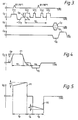
- a 90° r.f. excitation pulse B1(90) is first applied in the presence of a slice selection gradient G1 z , the gradient G1 z being followed by a rephasing reverse direction gradient pulse -G1 z as described above.
- a first large flow encoding gradient pulse G2 z is then applied followed at a time t D later by an identical flow encoding gradient pulse G5 z .
- the second flow encoding pulse G5 z there is applied a phase encoding gradient G y , and data collection is carried out during application of a gradient G x preceded by a reverse gradient -G x as described above.
- ⁇ the gyromagnetic ratio for hydrogen protons
- G p the magnitude of the gradient pulses
- G5 z t p is the duration of the gradient pulses G2 z and G5 z
- v is the velocity of flow
- the time periods t p , t A and t B are taken as extending from and to the mid-points of the relevant pulse edges.
- the slopes of the tops of the gradient pulses P1, P2 are assumed to be small compared with that of their edges so that their effects can be neglected.
- the above procedures may also be conveniently used to prevent interference with the detected r.f. signals by eddy currents produced by the spoiler gradient pulses G3 z and G4 z of Figure 3.
- Another particular example of a gradient pulse to which the invention may be applied is a field echo rephasing gradient pulse in an angiography experiment.
- the number of pulse edges and hence pulses required to eliminate eddy currents may be expected to increase as the number of eddy currents of different time constant increases.
- a gradient pulse pattern comprising a single pulse only will be required and the eddy current eliminated by suitable choice of the slope of the trailing edge of the single pulse.
- Measurement of the time constants of the eddy currents produced in a particular apparatus is conveniently carried out using a magnetic resonance probe, i.e. a probe which produces an output signal by virtue of excitation of magnetic resonance of material, e.g. doped water, contained in the probe.
- a magnetic resonance probe i.e. a probe which produces an output signal by virtue of excitation of magnetic resonance of material, e.g. doped water, contained in the probe.
- the signal emitted by the probe when excited by an r.f. magnetic field pulse applied to the probe is recorded.
- Comparison of the signal recorded when the r.f. pulse is preceded by a gradient pulse designed to produce eddy currents with the signal recorded in the absence of the gradient pulse enables the magnetic fields persisting after the gradient pulse, i.e. due to eddy currents, to be analysed.
- the method according to the invention has the advantages that it can be used without knowledge of or assumptions regarding the locations in which eddy currents are produced and can be applied regardless of the nature of the eddy currents. Furthermore, no apparatus modification is normally required, although the apparatus is required to provide good control of applied gradient pulses.
Landscapes
- Physics & Mathematics (AREA)
- Health & Medical Sciences (AREA)
- General Health & Medical Sciences (AREA)
- Nuclear Medicine, Radiotherapy & Molecular Imaging (AREA)
- Radiology & Medical Imaging (AREA)
- Engineering & Computer Science (AREA)
- Signal Processing (AREA)
- High Energy & Nuclear Physics (AREA)
- Condensed Matter Physics & Semiconductors (AREA)
- General Physics & Mathematics (AREA)
- Magnetic Resonance Imaging Apparatus (AREA)
Applications Claiming Priority (4)
| Application Number | Priority Date | Filing Date | Title |
|---|---|---|---|
| GB8830095 | 1988-12-23 | ||
| GB888830095A GB8830095D0 (en) | 1988-12-23 | 1988-12-23 | Magnetic resonance methods |
| GB8907364 | 1989-03-31 | ||
| GB898907364A GB8907364D0 (en) | 1989-03-31 | 1989-03-31 | Magnetic resonance methods |
Publications (2)
| Publication Number | Publication Date |
|---|---|
| EP0379802A2 true EP0379802A2 (fr) | 1990-08-01 |
| EP0379802A3 EP0379802A3 (fr) | 1991-04-24 |
Family
ID=26294766
Family Applications (1)
| Application Number | Title | Priority Date | Filing Date |
|---|---|---|---|
| EP19890313321 Withdrawn EP0379802A3 (fr) | 1988-12-23 | 1989-12-20 | Procédé de résonance magnétique |
Country Status (3)
| Country | Link |
|---|---|
| US (1) | US5015955A (fr) |
| EP (1) | EP0379802A3 (fr) |
| JP (1) | JPH02264636A (fr) |
Cited By (4)
| Publication number | Priority date | Publication date | Assignee | Title |
|---|---|---|---|---|
| WO1993014415A1 (fr) * | 1992-01-13 | 1993-07-22 | British Technology Group Ltd | Procede et appareil pour obtenir des informations par rmn |
| EP0752596A3 (fr) * | 1995-07-04 | 1997-04-16 | Marconi Gec Ltd | Procédés et appareil de résonance magnétique |
| GB2395793A (en) * | 2002-07-31 | 2004-06-02 | Ge Med Sys Global Tech Co Llc | Non-coupling magetic shielding MRI coil |
| DE19807306B4 (de) * | 1997-02-22 | 2010-10-14 | General Electric Co. | Verfahren zur Verringerung von Wirbelstromeffekten bei einer Diffusions-gewichteten Echo-Planar-Abbildung |
Families Citing this family (2)
| Publication number | Priority date | Publication date | Assignee | Title |
|---|---|---|---|---|
| US6272370B1 (en) | 1998-08-07 | 2001-08-07 | The Regents Of University Of Minnesota | MR-visible medical device for neurological interventions using nonlinear magnetic stereotaxis and a method imaging |
| US6463317B1 (en) | 1998-05-19 | 2002-10-08 | Regents Of The University Of Minnesota | Device and method for the endovascular treatment of aneurysms |
Family Cites Families (11)
| Publication number | Priority date | Publication date | Assignee | Title |
|---|---|---|---|---|
| GB1584949A (en) * | 1978-05-25 | 1981-02-18 | Emi Ltd | Imaging systems |
| US4585995A (en) * | 1984-04-19 | 1986-04-29 | Technicare Corporation | Nuclear magnetic resonance eddy field suppression apparatus |
| US4680547A (en) * | 1985-06-10 | 1987-07-14 | General Electric Company | Gradient field switch for improved magnetic resonance imaging/spectroscopy system |
| US4703275A (en) * | 1985-07-25 | 1987-10-27 | Picker International, Inc. | Method and apparatus to compensate for eddy currents in magnetic resonance imaging |
| US4761612A (en) * | 1985-07-25 | 1988-08-02 | Picker International, Inc. | Programmable eddy current correction |
| EP0216523A3 (fr) * | 1985-08-27 | 1989-04-05 | Resonex, Inc. | Procédé pour l'imagerie par résonance magnétique nucléaire utilisant des gradients non-orthogonaux |
| US4698591A (en) * | 1986-01-03 | 1987-10-06 | General Electric Company | Method for magnetic field gradient eddy current compensation |
| EP0250718A1 (fr) * | 1986-06-30 | 1988-01-07 | Siemens Aktiengesellschaft | Alimentation de courant pour charge inductive, plus particulièrement pour bobine de gradient avec dispositif de commande et de régulation |
| US4950994A (en) * | 1988-03-07 | 1990-08-21 | General Electric Company | Gradient and polarizing field compensation |
| US4920316A (en) * | 1989-03-30 | 1990-04-24 | Siemens Medical Systems, Inc. | Method and apparatus for reducing base field shifts in a magnetic resonance device due to pulsed magnetic field gradients |
| US4965521A (en) * | 1989-08-11 | 1990-10-23 | Spectroscopy Imaging Systems | Method and apparatus for compensating eddy current effects in a magnetic resonance device having pulsed magnetic field gradients |
-
1989
- 1989-12-15 JP JP1324213A patent/JPH02264636A/ja active Pending
- 1989-12-20 EP EP19890313321 patent/EP0379802A3/fr not_active Withdrawn
- 1989-12-26 US US07/456,460 patent/US5015955A/en not_active Expired - Lifetime
Cited By (7)
| Publication number | Priority date | Publication date | Assignee | Title |
|---|---|---|---|---|
| WO1993014415A1 (fr) * | 1992-01-13 | 1993-07-22 | British Technology Group Ltd | Procede et appareil pour obtenir des informations par rmn |
| US5608322A (en) * | 1992-01-13 | 1997-03-04 | British Technology Group Limited | Method of and apparatus for obtaining NMR information |
| EP0752596A3 (fr) * | 1995-07-04 | 1997-04-16 | Marconi Gec Ltd | Procédés et appareil de résonance magnétique |
| US5675256A (en) * | 1995-07-04 | 1997-10-07 | Picker International, Inc. | Magnetic resonance methods and apparatus |
| DE19807306B4 (de) * | 1997-02-22 | 2010-10-14 | General Electric Co. | Verfahren zur Verringerung von Wirbelstromeffekten bei einer Diffusions-gewichteten Echo-Planar-Abbildung |
| GB2395793A (en) * | 2002-07-31 | 2004-06-02 | Ge Med Sys Global Tech Co Llc | Non-coupling magetic shielding MRI coil |
| GB2395793B (en) * | 2002-07-31 | 2006-05-31 | Ge Med Sys Global Tech Co Llc | Non-coupling magnetic shielding coil |
Also Published As
| Publication number | Publication date |
|---|---|
| US5015955A (en) | 1991-05-14 |
| EP0379802A3 (fr) | 1991-04-24 |
| JPH02264636A (ja) | 1990-10-29 |
Similar Documents
| Publication | Publication Date | Title |
|---|---|---|
| EP0096590B1 (fr) | Méthode et appareil de résonance magnétique nucléaire | |
| EP1178327A2 (fr) | Procédé de compensation et appareil pour l'imagerie par résonance magnétique | |
| US4520828A (en) | Nuclear magnetic resonance method and apparatus | |
| EP0112663B1 (fr) | Procédé et appareil à résonance magnétique nucléaire | |
| EP0100183B1 (fr) | Procédé et appareil de résonance magnétique nucléaire | |
| US4733183A (en) | Nuclear magnetic resonance methods and apparatus | |
| JP4493763B2 (ja) | 磁気共鳴イメージング装置及び画像サイズ可変装置 | |
| EP0161366B1 (fr) | Procédé et appareil de résonance magnétique nucléaire | |
| JPH0565179B2 (fr) | ||
| US5015955A (en) | Magnetic resonance methods | |
| US4646023A (en) | Nuclear magnetic resonance imaging | |
| EP0106551B1 (fr) | Procédé et appareil à résonance magnétique nucléaire | |
| US20030210048A1 (en) | Simultaneous MR data acquisition with multiple mutually desensitized RF coils | |
| US4683432A (en) | Nuclear magnetic resonance methods and apparatus | |
| US4703269A (en) | Nuclear magnetic resonance imaging methods and apparatus | |
| US5227726A (en) | Nuclear magnetic resonance methods and apparatus | |
| EP0129356A2 (fr) | Procédé et appareil de résonance magnétique nucléaire | |
| EP0109517A2 (fr) | Appareil de diagnostic par résonance magnétique nucléaire | |
| GB2160660A (en) | Nuclear magnetic resonance (NMR) imaging | |
| GB2253909A (en) | Coil arrangements in nuclear magnetic resonance apparatus | |
| Hanawa | 4887035 Magnetic resonance spectroscopy system | |
| Cole | 4887609 Apparatus and method for filtering electrocardiograph signals | |
| JPH0511980B2 (fr) |
Legal Events
| Date | Code | Title | Description |
|---|---|---|---|
| PUAI | Public reference made under article 153(3) epc to a published international application that has entered the european phase |
Free format text: ORIGINAL CODE: 0009012 |
|
| AK | Designated contracting states |
Kind code of ref document: A2 Designated state(s): DE FR GB NL |
|
| PUAL | Search report despatched |
Free format text: ORIGINAL CODE: 0009013 |
|
| AK | Designated contracting states |
Kind code of ref document: A3 Designated state(s): DE FR GB NL |
|
| 17P | Request for examination filed |
Effective date: 19911015 |
|
| STAA | Information on the status of an ep patent application or granted ep patent |
Free format text: STATUS: THE APPLICATION HAS BEEN WITHDRAWN |
|
| 18W | Application withdrawn |
Withdrawal date: 19930111 |