EP0379813A2 - Dispositif pour la mesure de formation géologiques à résolution spatiale fine - Google Patents
Dispositif pour la mesure de formation géologiques à résolution spatiale fine Download PDFInfo
- Publication number
- EP0379813A2 EP0379813A2 EP89403392A EP89403392A EP0379813A2 EP 0379813 A2 EP0379813 A2 EP 0379813A2 EP 89403392 A EP89403392 A EP 89403392A EP 89403392 A EP89403392 A EP 89403392A EP 0379813 A2 EP0379813 A2 EP 0379813A2
- Authority
- EP
- European Patent Office
- Prior art keywords
- source
- detector
- formation
- detector means
- density
- Prior art date
- Legal status (The legal status is an assumption and is not a legal conclusion. Google has not performed a legal analysis and makes no representation as to the accuracy of the status listed.)
- Granted
Links
Images


Classifications
-
- G—PHYSICS
- G01—MEASURING; TESTING
- G01V—GEOPHYSICS; GRAVITATIONAL MEASUREMENTS; DETECTING MASSES OR OBJECTS; TAGS
- G01V5/00—Prospecting or detecting by the use of ionising radiation, e.g. of natural or induced radioactivity
- G01V5/04—Prospecting or detecting by the use of ionising radiation, e.g. of natural or induced radioactivity specially adapted for well-logging
- G01V5/08—Prospecting or detecting by the use of ionising radiation, e.g. of natural or induced radioactivity specially adapted for well-logging using primary nuclear radiation sources or X-rays
- G01V5/12—Prospecting or detecting by the use of ionising radiation, e.g. of natural or induced radioactivity specially adapted for well-logging using primary nuclear radiation sources or X-rays using gamma or X-ray sources
Definitions
- the present invention relates generally to tools for investigating a borehole traversing an earth formation, and more particularly to fine spatial resolution gamma-gamma type tools which may be useful in determining the density and photoelectric absorption cross section (Pe) of formations.
- Gamma-gamma well logging instruments utilizing gamma ray sources and gamma (photon) detectors for obtaining indications of the density and Pe of the formation surrounding a borehole are well known.
- a typical such device comprises a sonde body containing a gamma ray radioisotopic source, and at least one gamma ray detector, typically a Nal crystal scintillator, separated in depth by about fifteen inches.
- the metallic body of the sonde provides shielding of the detector from directly penetrating gamma rays. Consequently most of the radiation detected by the detector travels through and interacts with the formation before returning to the sonde. Measurements of the intensity of this returning radiation, typically as a function of energy of the detected photons, provide information regarding physical properties of the formation.
- Photoelectric absorption is an interaction common for photon energies below about 150 keV.
- a photon is absorbed by the electronic system of an atom, leaving the atom in an excited or ionized state. Subsequently, the excited atom may reemit a low energy photon (fluoresence).
- fluoresence a low energy photon
- the Compton scattering interaction is important over the entire range of energies considered. It occurs when a photon scatters from an electron, undergoing a change of direction and a corresponding change in energy.
- E 662 keV (the energy of a gamma ray emitted by a Cesium 137 nuclide)
- the strength of the Compton or photoelectric interaction is characterized by a quantity called the (total) cross section for the interaction.
- the cross section is defined according to the following. For a beam of photons passing normally through a thin, uniform layer of material having thickness ⁇ t, and atomic number density p , the probability that a photon in the beam will have a specified interaction in the target is equal to ⁇ t, where a is the atomic cross section for that interaction.
- the atomic cross section is generally a function of the energy of the photon.
- the photon interacts with the entire atom, but the interactions are commonly represented in terms of the cross section per electron by normalizing to the atomic number Z and defining an appropriate average over all elements present in the formation.
- ⁇ c Compton cross section per electron
- r photoelectric cross section per electron
- T depends very strongly on Z according to Z"
- density measurements made by gamma-gamma devices are most directly measurements of electron density. Techniques for converting the resulting estimates to mass density values are well known to those skilled in the art and will not be discussed herein.
- the location of the "near" detectors of the art relative to the source is typically at a sufficiently great spacing such that the count rate of the received signal is inversely related to the density (by a complex function).
- the detector is placed in such close proximity to the gamma ray source that an increase of formation density provides an increased detector count rate.
- the obtained information is information which is essentially averaged over a certain depth of the formation (typically six to twenty-four inches), depending on the spacing of the detectors and the data utilized. Fine spatial resolution (e.g. two inches and less), however has not been obtainable with the existing tools in the industry. In fact, in order to obtain higher resolution, it has been suggested that both the source and detector be tightly collimated (i.e. the area of formation directly illuminated or viewed by the source or detector is limited to an angle on the order of a few degrees).
- a density or Pe tool In order for a density or Pe tool to be commercially acceptable, it should be capable of operating under the rigorous conditions of the borehole environment, and be capable of a precision of about .01-.03 gm/cc in density under typical logging speeds.
- an apparatus for obtaining fine spatial resolution indications of characteristics of an earth formation traversed by a borehole generally comprises a photon source which irradiates the earth formation, and in close proximity thereto, a photon detector which detects photons which have been Compton scattered by the formation. Either the source or the detector or both the source and detector are uncollimated (i.e. open) relative to the formation. The distance between the source and detector openings is chosen such that the response of the tool at energies of interest has non-negative density sensitivity to substantially all regions of the formation.
- the preferred distance is significantly less than one mean free path of the source photons interacting in formations having typical densities and Pe values, and preferably less than one-half that mean free path.
- the mean free path is about two inches in typical earth formations.
- a preferred aspect of the apparatus invention is a gamma ray shield located between the source and detector.
- the shield substantially reduces the number of gamma rays which reach the detector directly from said source and thereby increases the signal/noise ratio.
- Another aspect of the invention includes the capability of the detector to detect the energies of the scattered gamma rays as well as the number of events recorded. From the energy spectrum, a signal processing means may be used for helping determine the density and/or Pe of thin beds of the formation.
- Yet another aspect of the invention is the inclusion of two or more detectors either circumferentially or longitudinally spaced. With an extra longitudinally spaced detector, environmental corrections may be enhanced. With extra circumferentially spaced detectors (and, if desired additional sources), fine resolution of the circumferential changes in the formation characteristics may be had.
- One advantage of such circumferential measurements is the possibility of dip determinations.
- the preferred apparatus is useful for obtaining density and/or Pe determinations.
- deconvolution of the obtained measurements via data processing can be used to provide even finer resolution. Additional data processing for achieving optimal noise filtering and for providing environmentally corrected determinations can also be utilized.
- Common gamma-gamma devices work by making energy discriminated measurements of the intensity of gamma radiation which is emitted from a source in the sonde, interacts with the formation, and returns to the tool at the detector.
- the energy measurements convey information on the macroscopic Compton and photoelectric cross sections of the intervening earth materials.
- the fundamental length scale governing the transport of this radiation from source to detector is the mean free path (X(E)) of the gamma ray against interaction, where and where p e is the electron density, o c and 7 are the Compton and photelectric cross sections per electron, respectively, appropriately averaged over the elements present in the formation, and E is the photon energy.
- the scale of the gamma-gamma device is fixed by the distance between the source and detector apertures, D. It has been determined by the applicants herein that there is a qualitative difference in the nature of the transport physics, and thus in the relation between responses and properties, depending on whether D is greater or less than the mean free path (E).
- FIG. 6 A simple type of prior art gamma-gamma device is shown illustratively in Figure 6. Such a configuration is commonly referred to as a "single scatter" geometry due to the constraints on multiple scattering imposed by tight collimation.
- the formation may be divided into three distinct regions R1, R2, and R3.
- region R1 the source photon beam is attenuated by a factor e-Pe [ ⁇ c ( E ) + T -(E)] 1 , where E is the source energy and 1 1 is the path length of the photons through region R1.
- region R2 Compton scattering is essential to turn photons toward the detector. The probability of such scattering is proportional to p e°c (E).
- region R3 attenuation contributes a factor similar to that of region R1, except that the cross sections are evaluated at the scattered energy E.
- the intensity of radiation detected, I is thus proportional to ,
- gamma-gamma devices are calibrated by measuring their responses in materials of known density and P e .
- the formation density or P e is determined by relating the deviation of the measured response from the calibrated response to the deviation of the unknown property from the known calibrated value.
- each of the three terms corresponds to one of the three formation regions of Figure 6.
- region R2 increased scattering causes an increased response, and hence a positive term (1) is included.
- regions R1 and R3 increased scattering and absorption result only in attenuation of the photons, and hence the negative terms are included.
- the density sensitivity depends on whether incremental or decremental interactions dominate. This in turn depends solely on the path length of the photons through the formation measured in units of their (instantaneous) mean free path. If the total path length in units of the mean free path is less than 1, then it can be said that beneficial scattering dominates and S lpe is greater than zero. For longer total path lengths, the attenuation effects of decremental scattering and absorption dominate, and Sl pe is less than zero.
- the interactions in an earth formation are not as simple as set forth in relationship (3), as they usually involve substantial multiple scattering contributions.
- the gamma rays contributing to responses typically undergo several interactions in the formation.
- gamma ray contributions to responses in such devices may be analyzed in terms of spatially distributed sensitivity functions.
- small volume regions of the formation in the vicinity of the device may be considered, with a small increase in density either resulting in incremental scattering or incremental attenuation.
- the domination of one or the other determines the density sensitivity of the response to the region.
- the total sensitivity response to the formation is then the sum of the contributions from all such regions.
- the integral sensitivity of the detector to increases in formation density is invariably negative. This may be understood roughly as a consequence of the fact that relatively few of all the possible scattering events of the photons which could potentially contribute to the response actually serve to increase the probability that they will eventually reach the detector with the requisite energy. This is evident as photons which are scattered in the direction of the detector but are several mean free paths from the detector will most likely undergo additional interactions which are overwhelmingly decremental, at least until the photon reaches the vicinity of the detector.
- multiply scattered photon histories may contribute positively to the density sensitivity of the responses.
- the critical factor is the total path length of the photon's trajectory (in terms of the mean free path for its energy during each leg) compared to the number of scattering events it undergoes.
- each scattering event which increases the photon's probability of reaching the detector will contribute positively to the density sensitivity, while attenuation along each leg of the trajectory will contribute negatively.
- the balance between these two effects determines the net contribution.
- detected photons tend to have traveled further than one mean free path per scattering event, and hence result in a negative sensitivity.
- the source-detector spacing of the device is significantly less than approximately one mean free path, however, detected photons tend to have traveled less than one mean free path per scattering event, and hence result in a positive integral density sensitivity.
- the closely spaced configuration admits the possibility of having a device whose responses, at nearly all energies of interest, exhibit positive density sensitivity to nearly every region of the formation in its vicinity.
- An advantage of such a situation lies in the simplicity and robustness of the signal processing required in this case as compared to, e.g., the more complex spatial response of a single scatter type configuration as aforedescribed.
- the most straightforward means of achieving this situation is to have the region of the formation directly illuminated by the source, and the region of the formation directly viewed by the detector nearly coincide, so that almost any region of the formation can serve as the scattering point for single scattering contributions to the detector.
- collimation is preferably designed to provide the minimum possible restriction on the possibly singly and multiply scattered photon paths between the source and detector. Even though certain regions of the formation may be shadowed from making single scattering contributions to the detector, if the path lengths are short enough and if the multiplicity of likely multiply scattered photon paths is high enough, then the multiply scattered photons will contribute a net positive sensitivity from this region. Collimation which restricts photon paths outside of the region between source and detector apertures, on the other hand, is not detrimental to the design.
- a further advantageous consequence of enhancing the contribution of multiply scattered photons to the responses of the device of the invention is to increase the integral density sensitivities of these responses beyond what could be obtained from a single scatter type configuration.
- the maximum density sensitivity of a single scatter type measurement is one, with this limit obtained only for an exceedingly small distance between source and detector apertures.
- the integral sensitivities will be much less than one. This limit on the maximum sensitivity value, however, does not apply to multiply scattered trajectories. Thus, inclusion of such contributions to the responses can significantly increase the integral density sensitivities of the measurements.
- the sensitivity function can be determined for any given sourcedetector spacing for a tool, for known parameters.
- a "critical distance" may be said to exist for the movement of a photon in a formation such that for a given photon energy, and a given formation density and Pe, the photon becomes statistically more likely to be attenuated, (i.e. scattered out of a preferred trajectory, reduced in energy below a detection threshold, or absorbed) than Compton scattered in a desired direction and detected.
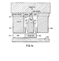
- a source 20a such as a Cs-137 or Co-60 source is distanced from a formation 25 by a distance of approximately one-quarter inch and is preferably located in its own pressure vessel 21a.
- a Nal or GSO (gadolinium ortho-silicate) detector 30a and an associated photomultiplier tube 31a Coaxial with, and approximately two and one-half inches directly behind the source 20a is a Nal or GSO (gadolinium ortho-silicate) detector 30a and an associated photomultiplier tube 31a.
- GSO gallium ortho-silicate
- Pressure housing 34a protects the detector 30a and photomultplier 31a while the pressure window 33a in the pressure housing 34a permits photons to enter the tool and be detected.
- a calibration source (not shown) may also be provided adjacent detector 30a. With the provided source-detector arrangement of Figure 1a, a longitudinal spacing of approximately zero is accomplished, as the axis of the center of the detector 30a extends through the source 20a.
- Generally cylindrical shielding 35a is provided between the source and detector to absorb gamma rays emitted from the source towards the detector. To prevent emitted gamma rays which are neither directed towards the detector 30a nor towards the formation 25 from finding their way to the detector 30a, additional shielding 38a is provided on the sides.
- the detector 30a is substantially uncollimated as the possible angles of photons being detected subscribes at least approximately thirty degrees (and in fact, approximately fifty-six degrees with the full detector 30a taken into account) as opposed to the more restrictive collimation found in much of the art as seen, e.g. in U.S. Patent Nos. 2,934,652 and 3,263,082 to Caldwell, 3,202,822, 3,840,746, and 3,846,631 to Kehler, and 4,034,218 to Turcotte.
- the source 20a is in essence totally uncollimated.
- Figure 1a has several advantages and several disadvantages as compared to the embodiments shown in Figures 1b and 1c, to be discussed hereinafter.
- the advantages include the ability to reduce the source strength to a relatively low 20 - 200 mCi, as well as the geometry providing an excellent signal/noise ratio, both of which are due to the source 20a being totally uncollimated relative to the formation 25.
- a further possible advantage concerns the compactness of the coaxial geometry which would be even a greater advantage with the use of a solid-state detector instead of Nal detector 30a or an ultra- compact photmultiplier instead of photomultiplier tube 31 a.
- the disadvantages include the slightly poorer vertical resolution relative to the other provided geometries (although the two inch resolution obtained is significantly better than that obtainable by the prior art), and the background contributed by the pressure- housing window 33a. It has been found, further, that increased vertical resolution may be obtained by segmenting detector 30a into at least two segments (such as segments 30a-1 and 30a-2 seen in Fig. 1d) and by partially collimating each segment (with collimation 35a-1 and 35a-2) as seen in Figure 1 d. Of course, the trade-off for the increased vertical resolution is the requirement of a higher source strength.
- the source strength necessary for high count rates is significantly lower than the configurations of the art having tight collimation, and the desired source strength is chosen accordingly preferably between 20 and 200 mCi, although stronger sources could be utilized in certain circumstances such as where high count rate detectors are employed.
- the source energy is also a matter of choice and depends mainly on the desired energy of the backscattered radiation as well as the ability to shield the detector from direct radiation.
- a high energy source such as Cs-137 is used in the preferred embodiment. If desired, higher energy sources such as Co-60 or lower energy sources such as Ba-133 may be used.
- the effective source-detector spacing is much less than the critical two inches, and in fact, close to zero.
- the measured signal is strongly scattering dominated as opposed to attenuation effect dominated, and a formation of increased density provides a higher count rate signal.
- the shielding between the sources and detectors is relatively thin, it is desirable to tailor the detector response so that it becomes somewhat transparent to the high- energy source gammas of the source, while being much more opaque (i.e. registering a count or event) for the lower energy backscattered radiation.
- a relatively thin detector is used.
- FIG. 1b a second embodiment (substantially collimated source - uncollimated detector) of the invention is seen.
- a source 20b is set back about three inches from the formation 25, while the detector 30b and its associated photomultiplier tube 31b are located directly behind pressure window 33b and pressure housing 34b, nearly adjacent the formation.
- the source 20b is substantially surrounded by shielding 35b to prevent gamma rays from source 20b from directly reaching detector 30b without entering formation 25.
- a path 40b is provided in shielding 35b to permit gamma rays to enter the formation.
- the path 40b is substantially collimated by shielding 35b which severely limits the angle opening from the source 20b to the formation 25 to about twelve degrees.
- shielding 35b may be non-cylindrical (e.g. elliptical in cross-section) to provide a wider angle opening in a plane going into and out of the paper of Figure 1b.
- the backscatter detector 30b of Figure 1 is separated from the formation only by a thin pressure housing window 33b, and is located within about one half an inch from the location of the furthest direct gamma ray path entering the formation which originates at the source.
- Associated photomultiplier 31 a is shielded from the formation by pressure housing 34b which also slightly collimates the detector. In essence, however, detector 30b is uncollimated relative to the formation, as window 33b provides an approximately ninety-degree opening.
- shielding 35b is very narrow adjacent the detector 30b, gamma rays exiting the formation at correct angles within an inch to the right of the detector 30b (in the orientation of Fig. 1b) might reach the detector unaffected.
- the Figure 1b embodiment has its advantages and disadvantages relative to the other preferred embodiments.
- the spatial resolution of the Fig. 1 device can be as small as one-half inch, which is substantially better than what is provided by the other two geometries, and the depth of investigation into the formation is somewhat deeper, particularly for low energy backscattered photons.
- the geometry of Figure 1 provides an excellent signal/background ratio as well as an excellent density sensitivity.
- 1b geometry is somewhat larger (at least 1.0 Ci.) than that required by the others, and the shielding of the detector between the detector and source requires more exacting geometries than that required by the others to prevent background noise as well as over- or under-shooting of results where density boundaries are traversed.
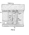
- FIG. 1 c The embodiment of Figure 1 c is in a sense the converse of the embodiment of Figure 1 b, as the source 20c is now open (uncollimated) to the formation 25 and the detector 30C is now substantially collimated.
- shielding 35c is used to reduce background from gamma rays emitted directly towards detector 30C from source 20C, and a pressure housing 34c with pressure window 33c therein is used to separate the detector 30C and its associated photomultiplier 31c from the formation 25 while permitting photons to enter the tool and be detected.
- shielding 35c is seen to be arranged so as to provide collimation which restricts the solid angle viewed by the detector 30a to approximately nineteen degrees. Again, if desired, non-cylindrical shielding could be provided.
- the distance between the source and the location of the furthest direct gamma ray path exiting the formation which terminates at the detector is slightly greater than one half an inch. Hence, positive sensitivity of the tool to increases in formation density is guaranteed.
- Figure 1c provides a mid-point in the relative advantages and disadvantages of the geometries of Figures 1 a and 1b.
- the source strength need not be as great as the source strength of Figure 1 b, as the source of Figure 1 c is open (uncollimated) to the formation.
- the source strength of source 20C must be greater than that of source 20a as detector 30C is substantially collimated while detector 30a is substantially uncollimated; and thus, a larger source is required in order to obtain the necessary count rate to permit a good statistical analysis.
- the vertical resolution of the Fig. 1c arrangement is between the resolutions of the other preferred embodiments.
- a set of measurements was obtained (see Figure 2) by moving the apparatus having a Nal crystal detector and a Cs137 662keV source through an artificial formation.
- the relative position of the changing formation elements is set forth in Figure 2, with the real densities and Pe being plotted over the length of the artificial formation as indicated. As may be seen, several of the formation layers are only one inch thick.
- the detected scattered gamma rays were divided into four energy windows, as indicated in four logs of Figure 2.
- the response at different energy levels, without signal processing or deconvolution, shows that the vertical resolution for a change in density is very good.
- the highest-energy window which corresponds to scattering in the small region just in front of the path for the collimated detector has an extremely sharp density response.
- the count rates for all but the lowest energy window are substantially linearly related to the formation density.
- the provided apparatus can provide extremely accurate indication of formation density with excellent resolution. By providing energy discrimination, the excellent resolution of density measurements may still be had for larger radial formation distances.
- FIG 3 a proposed borehole logging apparatus 100 incorporating the apparatus of the invention as seen in Figure 1a is seen in rough form.
- the apparatus 100 is shown in a borehole 114 which traverses formation 112.
- a mudcake 116 is shown on the interior wall of the borehole.
- the logging apparatus or sonde 100 is suspended in the borehole through the use of winch 104 and cable 142, and is urged against the borehole (mudcake) wall by means of a linkage (arm) 108 and eccentering skid 106 so that the gamma ray source 120 can be urged up close to the formation 112.
- the gamma ray source is preferably a pellet of Cs137 emitting gamma rays of an energy of 662 keV into the formation.
- shielding 135 Directly behind the gamma ray source 120 is shielding 135 in accord with the details of Figure 1a.
- Behind shielding 135 is a thin Nal gamma ray detector 127 which is comprised of crystal 130 and photomultiplier tube 131.
- detector electronics 132 Connected to the gamma ray detector 127 are detector electronics 132 which may be used to discriminate the pulses associated with the detector 127 into various energy windows.
- the processed information may then be sent via lead 103 to sonde transmission electronics 141 which may further process the information and send it uphole to surface instrumentation 140 via cable 142.
- sonde 100 may include a second Nal detector 134 which may be substantially open or collimated as desired.
- the second detector 134 is spaced at a long spacing (preferably at least four to six inches) from the source.
- Detector 134 is comprised of a crystal 137 and a photomultiplier tube 139 which is responsive to the flashes of the crystal 137.
- the photomultiplier tube 139 is connected to detector electronics 138 which can discriminate the pulses associated with the detected gamma rays into various energy windows.
- Detector electronics 138 is connected to sonde transmission electronics 141 via lead 105, and hence the information from the second detector 134 may be transmitted to the surface instrumentation 140.
- the sonde 100 is placed downhole, lowered to a desired longitudinal depth, and forced against the borehole wall by the opening of arm 108.
- the electronics are activated such that a count is made of the number of gamma rays detected in each of a plurality of predetermined energy windows.
- the count rate of preferably all of the windows, but at least one window density determinations may be made by equating density to a function of the count rates of the various windows.
- the Pe of the formation may be determined.
- an even more refined density and Pe measurement may be obtained by deconvolving the obtained information.
- the density for a particular location is determined as a function of the count rates in at least one of the energy windows at that location, and preferably at both previous and future locations.
- the effect of mudcake may be substantially eliminated by particularly processing information from the energy windows.
- the background (noise) due to detected gamma rays which were affected by an interaction with the shielding as well as those gamma rays which reach the detector directly from the source without having been scattered by the formation may be eliminated by obtaining background spectra out of the borehole (in air).
- background noise due just to non-scattered detected photons may be avoided by choosing energy windows carefully and thereby effectively filtering out the particular energy of such photons.
- an apparatus 180 having a plurality of sources 185a, 185b, 185c and detectors 188a, 188b, 188c radially spaced as pad devices 189a, 189b, and 189c and each arranged as the apparatus of Figure 1c is seen.
- apparatus 180 would extend arms 191a, 191b, 191c having their respective pad devices 189 such that the source 185 would be in close contact with the borehole 192.
- indications of formation characteristics at different circumferential locations around the borehole may be had. Then, by comparing results, the dip of the formation can be measured according to other techniques known in the art.
- each pad device 189 of Figure 5a could assume an arrangement as seen in Figure 5b, where a single uncollimated source 185a could be utilized along with an array of detectors such as detectors 188a-1, 188a-2..., 188a-6.
- the "critical distance" spacing (dictated by the mean free path) is really a rough limit on the source and detector locations.
- a more exact distance limit for a particular tool geometry, particular formation composition, particular energy source, et. is set by requiring that the tool show a non-negative response to an increase in density in the formation.
- additional limitations such as requiring that all energy windows of the detector show a non-negative response to an increase in density anywhere in the formation, or that all energy windows of the detector show a positive response to an increase in density in the vicinity of the source and detector might also be utilized to define the outer scope of the invention.
Landscapes
- Physics & Mathematics (AREA)
- High Energy & Nuclear Physics (AREA)
- Life Sciences & Earth Sciences (AREA)
- General Life Sciences & Earth Sciences (AREA)
- General Physics & Mathematics (AREA)
- Geophysics (AREA)
- Measurement Of Radiation (AREA)
- Analysing Materials By The Use Of Radiation (AREA)
- Geophysics And Detection Of Objects (AREA)
Applications Claiming Priority (2)
| Application Number | Priority Date | Filing Date | Title |
|---|---|---|---|
| US281577 | 1988-12-08 | ||
| US07/281,577 US4958073A (en) | 1988-12-08 | 1988-12-08 | Apparatus for fine spatial resolution measurments of earth formations |
Publications (3)
| Publication Number | Publication Date |
|---|---|
| EP0379813A2 true EP0379813A2 (fr) | 1990-08-01 |
| EP0379813A3 EP0379813A3 (fr) | 1993-01-27 |
| EP0379813B1 EP0379813B1 (fr) | 1995-01-11 |
Family
ID=23077879
Family Applications (1)
| Application Number | Title | Priority Date | Filing Date |
|---|---|---|---|
| EP89403392A Expired - Lifetime EP0379813B1 (fr) | 1988-12-08 | 1989-12-07 | Dispositif pour la mesure de formation géologiques à résolution spatiale fine |
Country Status (8)
| Country | Link |
|---|---|
| US (2) | US4958073A (fr) |
| EP (1) | EP0379813B1 (fr) |
| AU (1) | AU626952B2 (fr) |
| BR (1) | BR8905239A (fr) |
| DE (1) | DE68920568T2 (fr) |
| DK (1) | DK173147B1 (fr) |
| MX (1) | MX165496B (fr) |
| NO (1) | NO300476B1 (fr) |
Cited By (6)
| Publication number | Priority date | Publication date | Assignee | Title |
|---|---|---|---|---|
| EP0647859A1 (fr) * | 1993-10-06 | 1995-04-12 | Schlumberger Technology B.V. | Appareil de forage combiné |
| FR2722580A1 (fr) * | 1994-07-12 | 1996-01-19 | Services Petroliers Schlumberger | Procede et dispositif de diagraphie a patin pour la mesure de densite |
| WO1998008116A1 (fr) * | 1996-08-20 | 1998-02-26 | Schlumberger Technology B.V. | Appareil et procede de mesure de densite de trous de sondage rugueux |
| RU2258944C1 (ru) * | 2004-08-12 | 2005-08-20 | Иванов Александр Викторович | Прибор плотностного гамма-гамма-каротажа |
| EP1760495A1 (fr) | 2005-08-30 | 2007-03-07 | Services Petroliers Schlumberger | Sonde d'imagerie nucléaire |
| US9482233B2 (en) | 2008-05-07 | 2016-11-01 | Schlumberger Technology Corporation | Electric submersible pumping sensor device and method |
Families Citing this family (41)
| Publication number | Priority date | Publication date | Assignee | Title |
|---|---|---|---|---|
| FR2669743B1 (fr) * | 1990-11-23 | 1993-03-26 | Schlumberger Services Petrol | Dispositif de diagraphie a patin. |
| US5204529A (en) * | 1991-01-18 | 1993-04-20 | Texaco Inc. | Method and apparatus for measuring borehole fluid density, formation density and/or borehole diameter using back-scattered gamma radiation |
| US5377105A (en) * | 1991-04-12 | 1994-12-27 | Halliburton Logging Services | Enhanced vertical resolution processing of dual-spaced neutron and density tools |
| US5334833A (en) * | 1991-06-14 | 1994-08-02 | Schlumberger Technology Corporation | Sensitivity function technique for modeling nuclear tools |
| RU2105331C1 (ru) * | 1993-08-16 | 1998-02-20 | Малыхин Анатолий Яковлевич | Скважинный прибор для гамма-гамма-каротажа |
| FR2710989B1 (fr) * | 1993-10-06 | 1996-01-05 | Schlumberger Services Petrol | Dispositif de diagraphie à patin. |
| FR2710988B1 (fr) * | 1993-10-06 | 1996-01-05 | Schlumberger Services Petrol | Appareil de diagraphie comportant un patin de mesure, et dispositif combiné incluant un tel appareil. |
| US5583825A (en) * | 1994-09-02 | 1996-12-10 | Exxon Production Research Company | Method for deriving reservoir lithology and fluid content from pre-stack inversion of seismic data |
| US5804820A (en) * | 1994-09-16 | 1998-09-08 | Schlumberger Technology Corporation | Method for determining density of an earth formation |
| US5581024A (en) * | 1994-10-20 | 1996-12-03 | Baker Hughes Incorporated | Downhole depth correlation and computation apparatus and methods for combining multiple borehole measurements |
| US5619411A (en) * | 1994-12-02 | 1997-04-08 | Halliburton Company | Enhanced vertical resolution processing of dual-spaced density tools |
| EP0718641B1 (fr) * | 1994-12-12 | 2003-08-13 | Baker Hughes Incorporated | Système de forage muni d'un dispositif dans le puits pour transformer des multiples mesures de capteurs en des paramètres d'intérêt utilisés pour controller la direction de forage |
| CA2235134C (fr) | 1995-10-23 | 2007-01-09 | Baker Hughes Incorporated | Systeme de forage a boucle fermee |
| FR2782562B1 (fr) * | 1998-08-18 | 2000-09-29 | Cogema | Procede de simulation de la reponse d'un detecteur de rayonnements emis par des objets radioactifs et procede de controle d'elements de combustible nucleaire utilisant cette simulation |
| US7292942B2 (en) * | 2003-01-24 | 2007-11-06 | Schlumberger Technology Corporation | Measuring formation density through casing |
| US6891376B2 (en) * | 2003-07-01 | 2005-05-10 | Kjt Enterprises, Inc. | Method for attenuating conductive sonde mandrel effects in an electromagnetic induction well logging apparatus |
| US7286937B2 (en) * | 2005-01-14 | 2007-10-23 | Schlumberger Technology Corporation | Estimating formation properties from downhole data |
| US7649169B2 (en) * | 2005-03-21 | 2010-01-19 | Baker Hughes Incorporated | Method for determining shale bed boundaries and gamma ray activity with gamma ray instrument |
| MX2008001674A (es) | 2005-08-09 | 2008-04-07 | Hexion Specialty Chemicals Inc | Metodos y composiciones para la determinacion de la geometria de fractura en formaciones subterraneas. |
| US7566867B2 (en) * | 2006-06-14 | 2009-07-28 | Baker Hughes Incorporated | Apparatus and method for detecting gamma ray radiation |
| US7933718B2 (en) * | 2006-08-09 | 2011-04-26 | Momentive Specialty Chemicals Inc. | Method and tool for determination of fracture geometry in subterranean formations based on in-situ neutron activation analysis |
| US7800052B2 (en) * | 2006-11-30 | 2010-09-21 | Schlumberger Technology Corporation | Method and system for stabilizing gain of a photomultipler used with a radiation detector |
| EP1953571B1 (fr) * | 2007-02-05 | 2015-06-03 | Services Pétroliers Schlumberger | Dispositif nucléaire utilisé dans un puits pour déterminer une propriété de la formation |
| US8321131B2 (en) * | 2007-12-14 | 2012-11-27 | Schlumberger Technology Corporation | Radial density information from a Betatron density sonde |
| AU2009341852B2 (en) | 2009-03-11 | 2015-08-20 | Exxonmobil Upstream Research Company | Adjoint-based conditioning of process-based geologic models |
| AU2009341851B2 (en) | 2009-03-11 | 2015-07-16 | Exxonmobil Upstream Research Company | Gradient-based workflows for conditioning of process-based geologic models |
| US20100252725A1 (en) * | 2009-04-02 | 2010-10-07 | Recon Petrotechnologies., Ltd. | Logging tool and method for determination of formation density |
| AU2010249496B2 (en) | 2009-05-20 | 2016-03-24 | Halliburton Energy Services, Inc. | Downhole sensor tool with a sealed sensor outsert |
| SG176089A1 (en) * | 2009-05-20 | 2011-12-29 | Halliburton Energy Serv Inc | Downhole sensor tool for nuclear measurements |
| US8791407B2 (en) * | 2010-02-24 | 2014-07-29 | Halliburton Energy Services, Inc. | Gamma-gamma density measurement system for high-pressure, high-temperature measurements |
| US8692182B2 (en) | 2010-10-29 | 2014-04-08 | Baker Hughes Incorporated | Ruggedized high temperature compatible radiation detector |
| AU2012290435B2 (en) * | 2011-07-29 | 2014-11-20 | Shell Internationale Research Maatschappij B.V. | Method for increasing broadside sensitivity in seismic sensing system |
| US10073184B2 (en) * | 2012-02-06 | 2018-09-11 | Ion Geophysical Corporation | Sensor system of buried seismic array |
| US10197701B2 (en) | 2012-04-03 | 2019-02-05 | J.M. Wood Investments Ltd. | Logging tool for determination of formation density and methods of use |
| NO3071997T3 (fr) | 2013-11-18 | 2018-06-09 | ||
| US9759834B2 (en) | 2013-12-30 | 2017-09-12 | Halliburton Energy Services, Inc. | Method and apparatus for downhole photon imaging |
| CN105697002A (zh) * | 2014-11-24 | 2016-06-22 | 中国石油化工股份有限公司 | 一种用于识别煤系地层岩性的方法 |
| US20170139077A1 (en) * | 2015-03-17 | 2017-05-18 | Halliburton Energy Services, Inc | Optimization of Downhole Logging Tool Data Resolution |
| WO2018101903A1 (fr) | 2016-11-29 | 2018-06-07 | Halliburton Energy Services, Inc. | Détermination d'une caractéristique d'un matériau entourant un puits de forage sur la base de taux de comptage de photons diffusés |
| CA3020266C (fr) | 2017-10-10 | 2024-03-26 | Big Guns Energy Services Inc. | Systeme de test d'integrite mecanique et methode d'utilisation associee |
| US11933935B2 (en) * | 2021-11-16 | 2024-03-19 | Saudi Arabian Oil Company | Method and system for determining gamma-ray measurements using a sensitivity map and controlled sampling motion |
Family Cites Families (36)
| Publication number | Priority date | Publication date | Assignee | Title |
|---|---|---|---|---|
| US2778951A (en) * | 1952-12-12 | 1957-01-22 | Schlumberger Well Surv Corp | Neutron logging method and apparatus |
| US2997586A (en) * | 1955-08-16 | 1961-08-22 | Serge A Scherbatskoy | Gamma ray testing |
| US2934652A (en) * | 1956-08-13 | 1960-04-26 | Socony Mobil Oil Co Inc | Selected scattered gamma-ray density logging |
| US3202822A (en) * | 1961-11-13 | 1965-08-24 | Phillips Petroleum Co | Method of determining density utilizing a gamma ray source and a pair of detectors |
| US3223968A (en) * | 1962-12-03 | 1965-12-14 | Phillips Petroleum Co | Multiple electrical transmission system utilizing common conductors |
| US3321625A (en) * | 1962-12-10 | 1967-05-23 | Schlumberger Technology Corp | Compensated gamma-gamma logging tool using two detectors of different sensitivities and spacings from the source |
| US3197638A (en) * | 1963-01-21 | 1965-07-27 | Kenneth F Sinclair | Backscatter flaw detection system |
| US3263082A (en) * | 1963-06-17 | 1966-07-26 | Mobil Oil Corp | Geological prospecting comprising directional irradiation and detection |
| US3373286A (en) * | 1964-09-18 | 1968-03-12 | Industrial Nucleonics Corp | Device for measuring the characteristics of a material moving on a conveyor with means for minimizing the effect of flutter |
| US3407300A (en) * | 1966-04-14 | 1968-10-22 | Picker Corp | Collimator and method of making same |
| US3509341A (en) * | 1966-06-01 | 1970-04-28 | Picker Corp | Multiple detector radiation scanning device |
| US3321627A (en) * | 1966-10-07 | 1967-05-23 | Schlumberger Ltd | Gamma-gamma well logging comprising a collimated source and detector |
| US3864569A (en) * | 1970-04-14 | 1975-02-04 | Schlumberger Technology Corp | Well logging processing method and apparatus |
| US3710112A (en) * | 1970-05-18 | 1973-01-09 | Mobil Oil Corp | Method of indirectly monitoring the output of a pulsed neutron source |
| US3840746A (en) * | 1971-12-13 | 1974-10-08 | Applied Invention Corp | Gamma ray density probe utilizing a pair of gamma ray sources and a gamma ray detector |
| FR2168849B1 (fr) * | 1972-01-24 | 1976-09-03 | Schlumberger Prospection | |
| US3900733A (en) * | 1972-01-24 | 1975-08-19 | Schlumberger Technology Corp | Methods and apparatus for measuring the density of geological formations |
| US3846631A (en) * | 1972-03-13 | 1974-11-05 | Applied Invention Corp | Gamma ray differential density probe |
| FR2211664B1 (fr) * | 1972-12-21 | 1976-08-27 | Schlumberger Prospection | |
| FR2298680A1 (fr) * | 1975-01-24 | 1976-08-20 | Schlumberger Prospection | Procede et dispositif pour mesurer la densite des formations traversees par un forage |
| US4034218A (en) * | 1975-10-09 | 1977-07-05 | Schlumberger Technology Corporation | Focused detection logging technique |
| US4439831A (en) * | 1981-06-08 | 1984-03-27 | Schlumberger Technical Corporation | Digital induction logging system including autocalibration |
| US4445033A (en) * | 1981-09-14 | 1984-04-24 | Schlumberger Technology Corporation | Methods and apparatus for environmental correction of thermal neutron logs |
| US4490609A (en) * | 1982-06-23 | 1984-12-25 | Schlumberger Technology Corporation | Method and apparatus for analyzing well fluids by photon irradiation |
| US4604581A (en) * | 1983-01-11 | 1986-08-05 | Halliburton Company | Method and apparatus for deconvolving apparent conductivity measurements in induction well logging |
| US4712424A (en) * | 1984-01-26 | 1987-12-15 | Schlumberger Technology Corp. | Quantitative determination by elemental logging of subsurface formation properties |
| US4677596A (en) * | 1984-03-28 | 1987-06-30 | Mobil Oil Corporation | Method of detecting and correcting impulse noise errors in log data |
| US4661700A (en) * | 1985-05-28 | 1987-04-28 | Schlumberger Technology Corporation | Well logging sonde with shielded collimated window |
| US4691102A (en) * | 1985-06-17 | 1987-09-01 | Halliburton Company | Borehole compensation method and apparatus using variations in relative borehole components |
| US4703279A (en) * | 1985-07-31 | 1987-10-27 | Chevron Research Company | Method of interpreting impedance distribution of an earth formation penetrated by a borehole using precursor data provided by a moving logging array having a single continuously emitting current electrode and a multiplicity of potential electrodes |
| US4794792A (en) * | 1986-10-06 | 1989-01-03 | Schlumberger Technology Corporation | Method for determining formation characteristics with enhanced vertical resolution |
| US4909075A (en) * | 1986-10-06 | 1990-03-20 | Schlumberger Technology Corporation | Method for determining formation characteristics with enhanced statistical precision without degrading the vertical resolution or with enhanced vertical resolution |
| US4786796A (en) * | 1986-10-06 | 1988-11-22 | Schlumberger Technology Corporation | Method for determining formation characteristics with enhanced vertical resolution |
| US5157605A (en) * | 1987-04-27 | 1992-10-20 | Schlumberger Technology Corporation | Induction logging method and apparatus including means for combining on-phase and quadrature components of signals received at varying frequencies and including use of multiple receiver means associated with a single transmitter |
| US4800496A (en) * | 1987-09-28 | 1989-01-24 | Schlumberger Technology Corporation | Method for determining induction sonde error |
| US5151882A (en) * | 1990-08-08 | 1992-09-29 | Atlantic Richfield Company | Method for deconvolution of non-ideal frequency response of pipe structures to acoustic signals |
-
1988
- 1988-12-08 US US07/281,577 patent/US4958073A/en not_active Expired - Lifetime
-
1989
- 1989-10-05 MX MX017852A patent/MX165496B/es unknown
- 1989-10-16 BR BR898905239A patent/BR8905239A/pt not_active IP Right Cessation
- 1989-12-07 NO NO894918A patent/NO300476B1/no not_active IP Right Cessation
- 1989-12-07 EP EP89403392A patent/EP0379813B1/fr not_active Expired - Lifetime
- 1989-12-07 DK DK198906165A patent/DK173147B1/da not_active IP Right Cessation
- 1989-12-07 DE DE68920568T patent/DE68920568T2/de not_active Expired - Fee Related
- 1989-12-07 AU AU46007/89A patent/AU626952B2/en not_active Expired
-
1990
- 1990-08-16 US US07/568,282 patent/US5282133A/en not_active Expired - Fee Related
Cited By (11)
| Publication number | Priority date | Publication date | Assignee | Title |
|---|---|---|---|---|
| EP0647859A1 (fr) * | 1993-10-06 | 1995-04-12 | Schlumberger Technology B.V. | Appareil de forage combiné |
| FR2710987A1 (fr) * | 1993-10-06 | 1995-04-14 | Schlumberger Services Petrol | Dispositif de diagraphie combiné. |
| CN1044039C (zh) * | 1993-10-06 | 1999-07-07 | 施伦伯格海外公司 | 组合式测井装置 |
| FR2722580A1 (fr) * | 1994-07-12 | 1996-01-19 | Services Petroliers Schlumberger | Procede et dispositif de diagraphie a patin pour la mesure de densite |
| WO1998008116A1 (fr) * | 1996-08-20 | 1998-02-26 | Schlumberger Technology B.V. | Appareil et procede de mesure de densite de trous de sondage rugueux |
| GB2332745A (en) * | 1996-08-20 | 1999-06-30 | Schlumberger Ltd | Apparatus and method for measuring formation density in rugose boreholes |
| GB2332745B (en) * | 1996-08-20 | 2001-01-17 | Schlumberger Ltd | Apparatus and method for measuring formation density in rugose boreholes |
| RU2258944C1 (ru) * | 2004-08-12 | 2005-08-20 | Иванов Александр Викторович | Прибор плотностного гамма-гамма-каротажа |
| EP1760495A1 (fr) | 2005-08-30 | 2007-03-07 | Services Petroliers Schlumberger | Sonde d'imagerie nucléaire |
| US7439495B2 (en) | 2005-08-30 | 2008-10-21 | Schlumberger Technology Corporation | Nuclear imaging probe |
| US9482233B2 (en) | 2008-05-07 | 2016-11-01 | Schlumberger Technology Corporation | Electric submersible pumping sensor device and method |
Also Published As
| Publication number | Publication date |
|---|---|
| AU4600789A (en) | 1990-06-14 |
| DE68920568T2 (de) | 1995-08-31 |
| NO894918L (no) | 1990-06-11 |
| EP0379813B1 (fr) | 1995-01-11 |
| US5282133A (en) | 1994-01-25 |
| MX165496B (es) | 1992-11-13 |
| NO894918D0 (no) | 1989-12-07 |
| BR8905239A (pt) | 1990-07-31 |
| EP0379813A3 (fr) | 1993-01-27 |
| NO300476B1 (no) | 1997-06-02 |
| DE68920568D1 (de) | 1995-02-23 |
| DK616589D0 (da) | 1989-12-07 |
| DK173147B1 (da) | 2000-02-07 |
| US4958073A (en) | 1990-09-18 |
| DK616589A (da) | 1990-06-09 |
| AU626952B2 (en) | 1992-08-13 |
Similar Documents
| Publication | Publication Date | Title |
|---|---|---|
| EP0379813B1 (fr) | Dispositif pour la mesure de formation géologiques à résolution spatiale fine | |
| US3321625A (en) | Compensated gamma-gamma logging tool using two detectors of different sensitivities and spacings from the source | |
| CA2534304C (fr) | Outil de forage integre pour trou de forage | |
| US5525797A (en) | Formation density tool for use in cased and open holes | |
| CA2228991C (fr) | Dispositif gamma-gamma a multiples detecteurs pour mesurer la densite de formations | |
| US5023449A (en) | Nuclear spectroscopy signal stabilization and calibration method and apparatus | |
| EP0206867B1 (fr) | Dispositif de diagraphie | |
| US6495837B2 (en) | Geometrically optimized fast neutron detector | |
| US6639210B2 (en) | Geometrically optimized fast neutron detector | |
| US5451779A (en) | Formation density measurement apparatus and method | |
| US5627368A (en) | Four-detector formation-density tool for use in cased and open holes | |
| US6738720B2 (en) | Apparatus and methods for measurement of density of materials using a neutron source and two spectrometers | |
| US3321627A (en) | Gamma-gamma well logging comprising a collimated source and detector | |
| US4705944A (en) | Formation density logging while drilling | |
| EP0206593B1 (fr) | Procédé et dispositif de diagraphie avec moyens de compensation | |
| US4814611A (en) | Apparatus for measuring borehole-compensated densities and lithology-dependent factors using one or more detectors | |
| US3752984A (en) | Methods and system for detecting subsurface minerals | |
| CA1216681A (fr) | Diagraphie de densite d'un gisement au cours du forage | |
| US5847384A (en) | Method for determining irregularities in a wellbore wall using a gamma-gamma well logging instrument | |
| CA1256595A (fr) | Diagraphie de densite d'une formation geologique, faisant usage de deux detecteurs et sources | |
| NO309915B1 (no) | StrÕlings-detektor av scintillasjonstellertypen og fremgangsmÕte for analyse av strÕlingens energinivÕ | |
| Coope | Formation density logging while drilling | |
| GB2236177A (en) | Determination of core parameters using a gamma-gamma logging technique |
Legal Events
| Date | Code | Title | Description |
|---|---|---|---|
| PUAI | Public reference made under article 153(3) epc to a published international application that has entered the european phase |
Free format text: ORIGINAL CODE: 0009012 |
|
| AK | Designated contracting states |
Kind code of ref document: A2 Designated state(s): DE FR GB IT NL |
|
| PUAL | Search report despatched |
Free format text: ORIGINAL CODE: 0009013 |
|
| AK | Designated contracting states |
Kind code of ref document: A3 Designated state(s): DE FR GB IT NL |
|
| 17P | Request for examination filed |
Effective date: 19930603 |
|
| 17Q | First examination report despatched |
Effective date: 19940513 |
|
| GRAA | (expected) grant |
Free format text: ORIGINAL CODE: 0009210 |
|
| ITF | It: translation for a ep patent filed | ||
| AK | Designated contracting states |
Kind code of ref document: B1 Designated state(s): DE FR GB IT NL |
|
| REF | Corresponds to: |
Ref document number: 68920568 Country of ref document: DE Date of ref document: 19950223 |
|
| ET | Fr: translation filed | ||
| PLBE | No opposition filed within time limit |
Free format text: ORIGINAL CODE: 0009261 |
|
| STAA | Information on the status of an ep patent application or granted ep patent |
Free format text: STATUS: NO OPPOSITION FILED WITHIN TIME LIMIT |
|
| 26N | No opposition filed | ||
| REG | Reference to a national code |
Ref country code: GB Ref legal event code: IF02 |
|
| PGFP | Annual fee paid to national office [announced via postgrant information from national office to epo] |
Ref country code: FR Payment date: 20021210 Year of fee payment: 14 |
|
| PGFP | Annual fee paid to national office [announced via postgrant information from national office to epo] |
Ref country code: DE Payment date: 20021212 Year of fee payment: 14 |
|
| PGFP | Annual fee paid to national office [announced via postgrant information from national office to epo] |
Ref country code: NL Payment date: 20021227 Year of fee payment: 14 |
|
| PG25 | Lapsed in a contracting state [announced via postgrant information from national office to epo] |
Ref country code: NL Free format text: LAPSE BECAUSE OF NON-PAYMENT OF DUE FEES Effective date: 20040701 Ref country code: DE Free format text: LAPSE BECAUSE OF NON-PAYMENT OF DUE FEES Effective date: 20040701 |
|
| PG25 | Lapsed in a contracting state [announced via postgrant information from national office to epo] |
Ref country code: FR Free format text: LAPSE BECAUSE OF NON-PAYMENT OF DUE FEES Effective date: 20040831 |
|
| NLV4 | Nl: lapsed or anulled due to non-payment of the annual fee |
Effective date: 20040701 |
|
| REG | Reference to a national code |
Ref country code: FR Ref legal event code: ST |
|
| PG25 | Lapsed in a contracting state [announced via postgrant information from national office to epo] |
Ref country code: IT Free format text: LAPSE BECAUSE OF NON-PAYMENT OF DUE FEES;WARNING: LAPSES OF ITALIAN PATENTS WITH EFFECTIVE DATE BEFORE 2007 MAY HAVE OCCURRED AT ANY TIME BEFORE 2007. THE CORRECT EFFECTIVE DATE MAY BE DIFFERENT FROM THE ONE RECORDED. Effective date: 20051207 |
|
| PGFP | Annual fee paid to national office [announced via postgrant information from national office to epo] |
Ref country code: GB Payment date: 20081203 Year of fee payment: 20 |
|
| REG | Reference to a national code |
Ref country code: GB Ref legal event code: PE20 Expiry date: 20091206 |
|
| PG25 | Lapsed in a contracting state [announced via postgrant information from national office to epo] |
Ref country code: GB Free format text: LAPSE BECAUSE OF EXPIRATION OF PROTECTION Effective date: 20091206 |