EP0380202B1 - Vorrichtung und Verfahren zum zerstörungsfreien Ausbau von Gelenkstäben aus modularen Kunststoff-Förderbändern - Google Patents
Vorrichtung und Verfahren zum zerstörungsfreien Ausbau von Gelenkstäben aus modularen Kunststoff-Förderbändern Download PDFInfo
- Publication number
- EP0380202B1 EP0380202B1 EP19900300140 EP90300140A EP0380202B1 EP 0380202 B1 EP0380202 B1 EP 0380202B1 EP 19900300140 EP19900300140 EP 19900300140 EP 90300140 A EP90300140 A EP 90300140A EP 0380202 B1 EP0380202 B1 EP 0380202B1
- Authority
- EP
- European Patent Office
- Prior art keywords
- module
- apertures
- belt
- pivot rod
- pivot
- Prior art date
- Legal status (The legal status is an assumption and is not a legal conclusion. Google has not performed a legal analysis and makes no representation as to the accuracy of the status listed.)
- Expired - Lifetime
Links
Images




Classifications
-
- B—PERFORMING OPERATIONS; TRANSPORTING
- B65—CONVEYING; PACKING; STORING; HANDLING THIN OR FILAMENTARY MATERIAL
- B65G—TRANSPORT OR STORAGE DEVICES, e.g. CONVEYORS FOR LOADING OR TIPPING, SHOP CONVEYOR SYSTEMS OR PNEUMATIC TUBE CONVEYORS
- B65G17/00—Conveyors having an endless traction element, e.g. a chain, transmitting movement to a continuous or substantially-continuous load-carrying surface or to a series of individual load-carriers; Endless-chain conveyors in which the chains form the load-carrying surface
- B65G17/06—Conveyors having an endless traction element, e.g. a chain, transmitting movement to a continuous or substantially-continuous load-carrying surface or to a series of individual load-carriers; Endless-chain conveyors in which the chains form the load-carrying surface having a load-carrying surface formed by a series of interconnected, e.g. longitudinal, links, plates, or platforms
- B65G17/08—Conveyors having an endless traction element, e.g. a chain, transmitting movement to a continuous or substantially-continuous load-carrying surface or to a series of individual load-carriers; Endless-chain conveyors in which the chains form the load-carrying surface having a load-carrying surface formed by a series of interconnected, e.g. longitudinal, links, plates, or platforms the surface being formed by the traction element
-
- B—PERFORMING OPERATIONS; TRANSPORTING
- B65—CONVEYING; PACKING; STORING; HANDLING THIN OR FILAMENTARY MATERIAL
- B65G—TRANSPORT OR STORAGE DEVICES, e.g. CONVEYORS FOR LOADING OR TIPPING, SHOP CONVEYOR SYSTEMS OR PNEUMATIC TUBE CONVEYORS
- B65G2201/00—Indexing codes relating to handling devices, e.g. conveyors, characterised by the type of product or load being conveyed or handled
- B65G2201/02—Articles
-
- B—PERFORMING OPERATIONS; TRANSPORTING
- B65—CONVEYING; PACKING; STORING; HANDLING THIN OR FILAMENTARY MATERIAL
- B65G—TRANSPORT OR STORAGE DEVICES, e.g. CONVEYORS FOR LOADING OR TIPPING, SHOP CONVEYOR SYSTEMS OR PNEUMATIC TUBE CONVEYORS
- B65G2207/00—Indexing codes relating to constructional details, configuration and additional features of a handling device, e.g. Conveyors
- B65G2207/30—Modular constructions
Definitions
- This invention relates to a new and simple to manufacture conveyor belt modules which are pivotally connected by plastic pivot rods. More particularly this invention relates to such conveyor belts wherein the pivot rods are retained in assembled position without the need of forming "heads" on both ends of the pivot rods after the belt has been assembled. In addition, the pivot rods can be removed from the belt in a non-destructive manner and then reused.
- the modules are the type preferably formed by injection molding and which include first and second pluralities of pivot ends which are intermeshed with pivot ends of other modules and wherein the intermeshed pivot ends are held together by the pivot rods.
- the particular modules of this invention are formed with resilient members which normally obstruct movement of the pivot rods through apertures formed in the intermeshed link ends, but can be resiliently forced aside during insertion and/or removal of the pivot rods.
- a typical modular conveyor belt is disclosed in U.S. Patent 3,870,141 issued to J.M. Lapeyre on March 11, 1975.
- substantially indentical modules formed by injection molding are pivotally connected to one another to form a conveyor belt of a desired length.
- Each module includes a plurality of elongated elements, and each elongated element has a first pivot end and a second pivot end.
- the plurality of elongated elements are joined together such that the apertures defined in each of the first and second pluralities of pivot ends lie along a first and second pivot axis respectively which are parallel one to the other.
- the link ends of one module are intermeshed and pivotally connected by means of a pivot rod to the link ends of another module until an entire belt having the desired length is formed.
- Injection molded plastic belts built according to the teachings of this patent have been well received by industry and have many uses.
- U.S. Patent 4,051,949 issued on October 4, 1977 also to Lapeyre solved the problem of removing small and/or unstable articles from a conveyor belt without tipping over.
- the belt provides for a multiplicity of channels formed in the modules which receive the "teeth" of a comb to receive the articles.
- the belt disclosed in U.S. Patent 4,171,045, also issued to Lapeyre is similar to that described in US-A-3,870,141 and US-A-4,051,949 discussed above, except that selected ones of the vanes include a plurality of "dogs" which extend above the normal portion of the conveying surface to contact and push articles on the conveying surface along such that the belt will not slip underneath.
- U.S. Patent 4,213,527 issued June 22, 1980 to J. M. Lapeyre, et al further discloses a module for forming a link conveyor belt which has ridges or flight members extending transverse to the direction of travel for preventing the conveyor belt from slipping under articles riding on the conveyor belt surface.
- EP-A-0,032,797 discloses a conveyor belt formed of honeycomb-type modules connected together by transverse rods. The preamble of claim 1 is based on said prior art.
- a plastic modular belt sold by the Cambridge Wire Cloth Company of Cambridge, Maryland under the name of Cam-Clean (R) and substantially described in U.S. Patent No. 4,557,374 issued on December 10, 1985 to Robert H. Bode is driven in the center area of a module by a sprocket tooth received by a recess in the module defined by a pair of transverse connecting members.
- the first plurality of link ends are offset one link width with respect to the second plurality of link ends.
- the length of each module is determined by the distance between the first and second pivot axis, and the width of the module is determined by the number of link ends joined together by the centrally located connecting structure or member. Since the first and second pivot axes defined by the first and second pluralities of link ends are parallel, these axes lie in a common plane. The thickness of each of the pivot ends which surrounds the pivot axis is less than the spacing between adjacent pivot ends so that the pivot ends of one module may be intermeshed and connected with the pivot ends of another module by means of a pivot rod when the pivot axis of the two modules are aligned coaxially.
- Fig 1 is a perspective view of a plastic modular conveyor belt incorporating the features of this invention.
- Fig 2A, 2B, 2C and 2D are top, side, bottom and front view respectively of the module of Fig 1.
- Fig 3 is a diagrammatic sketch showing how the belt of this invention may be brick-layed to form a belt of any selected width.
- Fig 4 is a front view similar to Fig 2D showing a "headless" pivot rod in place.
- Fig 5A, 5B, 5C and 5D are top, side, bottom and front views respectively of a different embodiment of a module incorporating the teachings of this invention.
- Fig 6A and 6B are side and front views respectively which are similar to Figs 5B and 5D except they include a "headed" pivot rod snapped in place.
- Fig 7A is a partially sectional top view of another embodiment of the present invention, particularly suitable for open area belts.
- Fig. 7B is a side view of one of the modules of Fig. 7A.
- Fig. 7C is a bottom view of a portion of one of the modules of Fig. 7A.
- Fig. 8A is a perspective view of three intermeshed modules of another embodiment of the present invention.
- Fig. 8B is a side view of a module of Fig. 8A.
- Figs. 9A and 9B are top and side views respectively of another embodiment of the present invention.
- Figs. 10, 11A, 11B and 11C show a perspective view, a side view, a front view and a top view respectively of another embodiment of this invention.
- FIG. 1 there is shown generally at 10 a section of a plastic modular conveyor belt which incorporates the features of this invention.
- Figs. 2A, 2B, 2C and 2D are various views of a module 12 of belt 10.
- a series of modules 12, 14, 16 and 18 are pivotally connected or joined by means of pivot rods 20, 22 and 24 which extend through apertures such as apertures 26, 28 and 30 defined in the end of elongated links 32, 34 and 36 of module 12.
- the modules 12 through 18 as shown in Fig. 1 are illustrated with only three elongated links such as elongated links 32, 34 and 36 of module 12.
- modules 14 and 18 are not exactly the same as modules 12 and 16. Specifically, the edges 38A and 38B of modules 12 and 16 are somewhat wider than edges 40A and 40B of module 14 and 18. Further edges 38A and 38B of modules 12 and 16 include spaces 42A and 42B to receive the link end of a pivotally connected module, such as link end 44 of module 14 is received by space 42B of module 16. The difference in thickness allows for a straight and smoother edge. Other than the space and increased thickness, modules 12 and 16 are the same as modules 14 and 18.
- conveyor belts are required to be in all sizes of width and length, to accomplish various types of conveying needs. Consequently, it is hightly desirable that the belting system be made of modules or units which can be plaed together in an end-to-end and side-by-side relationship so as to form a belt of any width and length.
- Fig. 3 illustrates how belts made of modules of the types discussed above may be made of identical modules having a single width along with a few partial or half modules so as to form a belt three modules wide but which also has substantially the strength of a single module across the belt.
- the strength of the belt is achieved as a result of the intermeshing and interlocking of the pivot ends.
- the full length modules 46A, 46B and 46C are simply laid side-by-side across the width of the belt.
- Each row on both sides of the row comprised of modules 46A, 46B and 46C include two full size rows such as modules 48A and 48B and two partial modules such as 48C and 48D.
- edge portion 38A which is integrally molded to elongated link 32 includes a stop member 50.
- stop member 50 extends from the top surface of edge 38A such that it partially obstructs aperture 26 which is defined in elongated link 32.
- Fig. 4 is substantially the same as Fig. 2D, except it shows a pivot rod 54 having a diameter substantially the same size (although slightly smaller) in place within the apertures 26 and 28. As can be seen, the tip portion of stop member 50 would contact edge 56 of pivot rod 54 and prevent, or at least restrict, the movement of the pivot rod in the direction opposite of that indicated by arrow 52.
- the dotted lines 58 in Fig. 4 illustrate how the stop member 50 could allow pivot rod 54 to be forcefully inserted (or removed) by being deformed by the end of the pivot rod indicated by dotted lines 60.
- Figs. 5A, 5B, 5C, 5D, 6A and 6B there are shown various views of another embodiment of the present invention on a different type of module indicated generaly at 62.
- link ends 64 and 66 on one side of the module are offset from the link ends 68 and 70 on the other side of the module by an amount equal to or slightly greater than the thickness of a link end. This amount of offset in the link ends makes the task of providing aligned edges of connected link ends much easier.
- a conveyor belt constructed from modules similar to module 62 will be center driven by applying a force orthogonal to cross-member 72, and will have a flush, smooth top.
- link end 70 includes two ramp shaped stop members 74 and 76 which obstruct aperture 78 formed in link end 70.
- Stop members 74 and 76 will freely allow a pivot rod 80 (Fig. 6B) to be inserted in the direction indicated by arrow 82 through apertures 78 and 84 in link ends 70 and 68 respectively as well as through apertures of intermeshed link ends from another module.
- stop members 74 and 76 will obstruct the passage of the head 86 such that these stop members must be deformed or bent out of position before head 86 can move past stop members 74 and 76 to the seated position indicated by dotted lines 88.
- pivot rod 80 can be removed by either forcing head 86 past stop members 74 and 76 or by simply cutting head 86 from pivot rod 82.
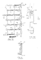
- Figs. 7A, 7B and 7C there is shown still another embodiment of the present invention incorporated into a module used in fabricating very light weight and open area conveyor belts, such as the portion of a conveyor belt indicated generally at 90.
- the belt 90 includes integrally molded modules 92, 94 and 96 typically connected by pivot rods 98 and 100.
- pivot rods 102 and 104 are also shown in position in link ends 106 and 108 of modules 92 and 96 respectively, but are not shown as connecting other modules.
- edge members 110A, 110B and 110C are integrally molded to each module.
- Each edge member 110A, 110B and 110C includes a support structure such as sleeve portion 112A and 112C, and an obstruction abutment or stop member such as 114A and 114C.
- modules of belt 90 are assembled by inserting the pivot rod through the intermeshed link ends in a direction as indicated by arrow 116.
- the stop member portion of a module edge must be deformed or bent out of the way to allow insertion of the pivot rod into and through the sleeve portion and the link ends. As shown, in Figs.
- the obstruction portion, abutment or stop member of a module edge is bent or deformed out of the usual position, and a rod such as rod 102 is passed through a sleeve and the link end, such as sleeve 112A and apertures 118 and 120 of link end 106, in the direction indicated by arrow 116.
- the stop member or abutment portion of the adjacent module returns to its normal or undeformed position surrounding the sleeve portion so as to prevent the rod from moving in a direction opposite that indicated by arrow 116.
- pivot rod 100 may extend substantially to the end of sleeve 112C such that it would be almost in contact with the stop member portion (broken away and not shown) of edge 110B of module 94.
- the pivot rod may terminate well short of the abutment or stop member without detrimental effect as is indicated by pivot rod 104 and abutment or stop member 114C.
- the abutment or stop member portion 114B of module 94 may be bent out of the way of sleeve portion 112C of module 96, and how the obstruction, abutment or stop member portion 114B includes a keyhole shaped cut-out proving a passage 126B from the bottom-most edge portion 128B of edge 110B such that the obstruction or stop member portion 114B can snap around and surround the sleeve 112C when it returns to its normal and undeformed position.
- the cylindrical receiving recess portion 130 indicated by dotted lines is substantially the same diameter, or somewhat greater than the diameter of the sleeve portion 132 of the same and other modules.
- the cut-out or passageway to the cylindrical portion is equal to or slightly less than the diameter of the sleeve 112C of module 96 such that the stop member portion 114B of module 94 snaps around and surrounds the sleeve portion 112C of a pivotally connected module 96.
- a smooth edge is provided and headless pivot rods are completely restrained from axial movement out of a connecting relationship without the use of separate or unattached plugs and/or obstructions.
- the edge 136 of a selected module includes top ramp shaped abutments or stop members 138A and 138B, and bottom ramp shaped abutments or stop members 140A and 140B.
- the body 142 of a pivot rod can easily pass the stop members 138B and 140B into aperture 144B, whereas the head 146 must be forced past stop members 138B and 140B so as to be seated in the gap 148A or 148B between the stop member and the edge portion defining aperture 144A and 144B. Once the head 146 is in position in gap 148B the pivot rod is substantially restricted from any axial movement.
- Figs. 9A and 9B show top and side views of yet another embodiment of the invention.
- a curved ramp shaped abutment 150 will allow the passage of the body of a pivot rod into aperture 152 of side link 154 and on into and through the apertures defined in the link end such as aperture 156 in link end 158.
- the enlarged head of a pivot rod must be forced past stop member 150 into the gap 160 between the surface 162 of side 154 and stop member 150. Once in place, the "headed" rod is restrained from any axial movement.
- Figs. 10, 11A, 11B and 11C show yet another belt style incorporating the features of this invention.
- modules 164, 166 and 168 are pivotally connected by "headless" pivot rods 170 and 172.
- a ramp shaped abutment or stop member such as stop members 174A, 174B and 174C, partially obstruct insertion of a pivot rod into the apertures of the link end in close proximity to the stop members.
- the pivot rod, the abutment, or both must be deformed to allow the pivot rod to be inserted into the apertures of intermeshed link ends of two modules.
- Figs. 11A, 11B and 11C show other views of the module 164.
Landscapes
- Engineering & Computer Science (AREA)
- Mechanical Engineering (AREA)
- Chain Conveyers (AREA)
Claims (4)
- Förderband mit mehreren Förderbandmodulen (12, 14), die jeweils in einer End-zu-End-Verbindung mit Hilfe von Gelenkstangen (20, 22), die sich axial durch Öffnungen (26) in ineinander greifenden Verbindungsenden (32, 34, 36) an den End-zu-End-Verbindungen (12, 14) erstrecken, gelenkig verbunden sind und zumindest zwei Verbindungsglieder (12, 14) nahe einer Seite (38A, 40A) des Förderbandes darstellen, wobei die Öffnungen (26) zum Einführen und Entfernen der Gelenkstangen (20) zugänglich sind,
wobei das Fördermodul (12) eine Halteeinrichtung (38A) aufweist, um eine Gelenkstange (20), die sich axial durch mehrere Öffnungen (26) in den Enden (32, 34, 36) von entsprechenden ersten und zweiten, jeweils in einer End-zu-End-Verbindung gelenkig miteinander verbundenen Verbindungsgliedern (12, 14) erstreckt, axial entfernbar festzuhalten, und diese Halteeinrichtung eine einstückig geformte, im Randbereich liegende Stützstruktur (50, 94, 114B) an einem der beiden jeweils eine Seite des Förderbandes bildenden Verbindungsglieder und zudem Anschläge (50) aufweist, die bei zusammengesetztem Förderband die Öffnungen (26) abdecken, um die Gelenkstange (20) am Herausgleiten aus den Öffnungen (26) zu hindern,
wobei diese im Randbereich liegende Stützstruktur ferner elastisch biegbare Mittel (94, 114B) aufweist, die es dem Anschlag (50) erlauben, sich aus seiner die Öffnungen bei zusammengesetztem Förderband abdeckenden Position herauszubewegen, so daß die Gelenkstange (20) in die Öffnungen eingeschoben und aus diesen entfernt werden kann,
dadurch gekennzeichnet, daß die elastisch biegbaren Mittel (94, 114B) einen Ausschnitt (126B) begrenzen, der gegen die Stützstruktur (112C) eines schwenkbar verbundenen Modules (110C) gerichtet ist und dieses zumindest teilweise umgibt. - Förderbandmodul nach Anspruch 1, wobei die Gelenkstange (20) eine Gewindestange ist.
- Förderbandmodul nach einem der vorhergehenden Ansprüche, wobei die elastisch biegbaren Mittel jeweils ein Verbindungsende eines Modules umfassen.
- Förderbandmodul nach Anspruch 3, wobei das deformierbare Verbindungsende eines Modules in ein weiteres Modul in einer End-zu-End-Verbindung um die Stützstruktur (112C) eingreift, durch die die Gelenkstange (100) axial hindurchgeht.
Applications Claiming Priority (4)
| Application Number | Priority Date | Filing Date | Title |
|---|---|---|---|
| US30254289A | 1989-01-26 | 1989-01-26 | |
| US302541 | 1989-01-26 | ||
| US07/302,541 US4949838A (en) | 1988-11-14 | 1989-01-26 | Apparatus and methods to allow non-destructive removal of pivot rods in modular plastic conveyor belts |
| US302542 | 1989-01-26 |
Publications (2)
| Publication Number | Publication Date |
|---|---|
| EP0380202A1 EP0380202A1 (de) | 1990-08-01 |
| EP0380202B1 true EP0380202B1 (de) | 1993-11-10 |
Family
ID=26972976
Family Applications (1)
| Application Number | Title | Priority Date | Filing Date |
|---|---|---|---|
| EP19900300140 Expired - Lifetime EP0380202B1 (de) | 1989-01-26 | 1990-01-05 | Vorrichtung und Verfahren zum zerstörungsfreien Ausbau von Gelenkstäben aus modularen Kunststoff-Förderbändern |
Country Status (2)
| Country | Link |
|---|---|
| EP (1) | EP0380202B1 (de) |
| DE (1) | DE69004443T2 (de) |
Families Citing this family (6)
| Publication number | Priority date | Publication date | Assignee | Title |
|---|---|---|---|---|
| US5156262A (en) * | 1990-11-08 | 1992-10-20 | The Laitram Corporation | Conveyor belt module drive surfaces for mating with sprocket drive surface in the hinging region |
| US5706934A (en) * | 1994-11-14 | 1998-01-13 | Kvp Systems, Inc. | Modular solid top plastic conveyor belt |
| JP3533454B2 (ja) * | 1996-11-29 | 2004-05-31 | 山久チヱイン株式会社 | コンベア・チェーン・ユニット及びコンベア・チェーン |
| JP3331464B2 (ja) | 1999-03-25 | 2002-10-07 | 山久チヱイン株式会社 | 合成樹脂製コンベアチェーンに於ける連結ピンの抜止め装置 |
| DE102011114250A1 (de) * | 2011-09-23 | 2013-03-28 | Iwis Antriebssysteme Gmbh & Co. Kg | Förderkette |
| EP2788266B1 (de) * | 2011-12-06 | 2022-04-13 | Ashworth Bros., Inc. | Förderbandverbindung mit stangenrückhaltung |
Family Cites Families (3)
| Publication number | Priority date | Publication date | Assignee | Title |
|---|---|---|---|---|
| IE50415B1 (en) * | 1980-01-15 | 1986-04-16 | Umec Boydell Belting Ltd | Conveyor belt of the honeycomb type |
| DE3241632C2 (de) * | 1982-11-11 | 1986-09-25 | Draadindustrie Jonge Poerink B.V., Borne | Aus Kunststoff-Gliedern bestehendes Förderband mit eingeschobenen Querstäben |
| CA1309054C (en) * | 1987-04-15 | 1992-10-20 | William G. Hodlewsky | Conveyor chain assembly |
-
1990
- 1990-01-05 EP EP19900300140 patent/EP0380202B1/de not_active Expired - Lifetime
- 1990-01-05 DE DE1990604443 patent/DE69004443T2/de not_active Expired - Fee Related
Also Published As
| Publication number | Publication date |
|---|---|
| EP0380202A1 (de) | 1990-08-01 |
| DE69004443D1 (de) | 1993-12-16 |
| DE69004443T2 (de) | 1994-04-14 |
Similar Documents
| Publication | Publication Date | Title |
|---|---|---|
| US5058732A (en) | Apparatus to allow non-destructive removal of pivot rods in modular plastic conveyor belts | |
| US5156264A (en) | Non-destructive pivot rod retention apparatus for modular plastic conveyor belts | |
| US4949838A (en) | Apparatus and methods to allow non-destructive removal of pivot rods in modular plastic conveyor belts | |
| CA1302340C (en) | Heavy duty modular conveyor belt and sprocket with unique tracking | |
| US5215185A (en) | Breakable molded plastic links for forming conveyor chain | |
| EP0380201A2 (de) | Förderbandmodul | |
| EP0064473B1 (de) | Transportkette zum Gebrauch bei einer mit Fingern versehenen Transferplatte | |
| EP0631950B1 (de) | Fördervorrichtung | |
| EP0113909B1 (de) | Leichtgewichtmodul für Transportband | |
| EP0551399B1 (de) | Kunststoff-förderband mit integrierten seitenplatten | |
| EP0175483B1 (de) | Förderband mit einsetzbaren und auswählbaren Förderelementen | |
| EP0787663B1 (de) | Gelenkstifte mit Kopf enthaltende modulare Förderkette | |
| EP1687221B1 (de) | Kunststoffförderbandmodule mit seitenschutz | |
| US4171045A (en) | Raised link modular conveyor belt | |
| EP0722896B1 (de) | Umlenkeinrichtung zum Überführen von Gegenständen zwischen Querförderern | |
| US4865183A (en) | Wide chain conveyor sprocket drive | |
| EP1427654B1 (de) | Modulares förderband mit nicht kreisförmigen gelenkbolzen | |
| EP0789662A1 (de) | Modulares kunststoff-förderband mit massiver oberfläche | |
| EP1277676A1 (de) | Seitenteil mit Schnappverschluss für Bandförderermodule | |
| US6079543A (en) | Lane-divided plastic conveyor belt | |
| AU2002361470A1 (en) | Modular conveyor belt with non-circular hinge pin | |
| US4821872A (en) | Lightweight modular conveyor belt | |
| EP0598453A1 (de) | Aus Kunststoff-Modulen zusammengesetzte Fördermatten und Module für solche Fördermatten | |
| EP0380202B1 (de) | Vorrichtung und Verfahren zum zerstörungsfreien Ausbau von Gelenkstäben aus modularen Kunststoff-Förderbändern | |
| EP0333309A1 (de) | Breiter Kettenförderer |
Legal Events
| Date | Code | Title | Description |
|---|---|---|---|
| PUAI | Public reference made under article 153(3) epc to a published international application that has entered the european phase |
Free format text: ORIGINAL CODE: 0009012 |
|
| AK | Designated contracting states |
Kind code of ref document: A1 Designated state(s): DE FR GB IT |
|
| 17P | Request for examination filed |
Effective date: 19910123 |
|
| 17Q | First examination report despatched |
Effective date: 19920601 |
|
| GRAA | (expected) grant |
Free format text: ORIGINAL CODE: 0009210 |
|
| AK | Designated contracting states |
Kind code of ref document: B1 Designated state(s): DE FR GB IT |
|
| ITF | It: translation for a ep patent filed | ||
| REF | Corresponds to: |
Ref document number: 69004443 Country of ref document: DE Date of ref document: 19931216 |
|
| ET | Fr: translation filed | ||
| PLBE | No opposition filed within time limit |
Free format text: ORIGINAL CODE: 0009261 |
|
| STAA | Information on the status of an ep patent application or granted ep patent |
Free format text: STATUS: NO OPPOSITION FILED WITHIN TIME LIMIT |
|
| 26N | No opposition filed | ||
| REG | Reference to a national code |
Ref country code: GB Ref legal event code: IF02 |
|
| PGFP | Annual fee paid to national office [announced via postgrant information from national office to epo] |
Ref country code: GB Payment date: 20061213 Year of fee payment: 18 |
|
| PGFP | Annual fee paid to national office [announced via postgrant information from national office to epo] |
Ref country code: DE Payment date: 20070131 Year of fee payment: 18 |
|
| PGFP | Annual fee paid to national office [announced via postgrant information from national office to epo] |
Ref country code: IT Payment date: 20070529 Year of fee payment: 18 |
|
| PGFP | Annual fee paid to national office [announced via postgrant information from national office to epo] |
Ref country code: FR Payment date: 20070103 Year of fee payment: 18 |
|
| GBPC | Gb: european patent ceased through non-payment of renewal fee |
Effective date: 20080105 |
|
| PG25 | Lapsed in a contracting state [announced via postgrant information from national office to epo] |
Ref country code: DE Free format text: LAPSE BECAUSE OF NON-PAYMENT OF DUE FEES Effective date: 20080801 |
|
| REG | Reference to a national code |
Ref country code: FR Ref legal event code: ST Effective date: 20081029 |
|
| PG25 | Lapsed in a contracting state [announced via postgrant information from national office to epo] |
Ref country code: GB Free format text: LAPSE BECAUSE OF NON-PAYMENT OF DUE FEES Effective date: 20080105 |
|
| PG25 | Lapsed in a contracting state [announced via postgrant information from national office to epo] |
Ref country code: FR Free format text: LAPSE BECAUSE OF NON-PAYMENT OF DUE FEES Effective date: 20080131 |
|
| PG25 | Lapsed in a contracting state [announced via postgrant information from national office to epo] |
Ref country code: IT Free format text: LAPSE BECAUSE OF NON-PAYMENT OF DUE FEES Effective date: 20080105 |