EP0380207A1 - Restitution de la gaine pour la soudure d'une fibre optique - Google Patents
Restitution de la gaine pour la soudure d'une fibre optique Download PDFInfo
- Publication number
- EP0380207A1 EP0380207A1 EP90300189A EP90300189A EP0380207A1 EP 0380207 A1 EP0380207 A1 EP 0380207A1 EP 90300189 A EP90300189 A EP 90300189A EP 90300189 A EP90300189 A EP 90300189A EP 0380207 A1 EP0380207 A1 EP 0380207A1
- Authority
- EP
- European Patent Office
- Prior art keywords
- mould
- plastics
- bore
- splice region
- plastics material
- Prior art date
- Legal status (The legal status is an assumption and is not a legal conclusion. Google has not performed a legal analysis and makes no representation as to the accuracy of the status listed.)
- Granted
Links
- 238000005253 cladding Methods 0.000 title claims abstract description 23
- 239000013307 optical fiber Substances 0.000 title description 12
- 239000004033 plastic Substances 0.000 claims abstract description 28
- 229920003023 plastic Polymers 0.000 claims abstract description 28
- 230000003287 optical effect Effects 0.000 claims abstract description 19
- 238000000034 method Methods 0.000 claims abstract description 14
- 238000000465 moulding Methods 0.000 claims abstract description 5
- 239000000463 material Substances 0.000 claims description 26
- 239000000835 fiber Substances 0.000 claims description 19
- 239000011521 glass Substances 0.000 claims description 9
- 230000000295 complement effect Effects 0.000 claims description 3
- 230000000694 effects Effects 0.000 claims description 3
- 238000007526 fusion splicing Methods 0.000 claims description 3
- 238000000576 coating method Methods 0.000 description 13
- 239000011248 coating agent Substances 0.000 description 12
- 230000004927 fusion Effects 0.000 description 4
- 239000002904 solvent Substances 0.000 description 4
- 238000004140 cleaning Methods 0.000 description 3
- 235000014820 Galium aparine Nutrition 0.000 description 1
- 240000005702 Galium aparine Species 0.000 description 1
- 238000007664 blowing Methods 0.000 description 1
- 238000005304 joining Methods 0.000 description 1
- 238000000926 separation method Methods 0.000 description 1
- 238000004506 ultrasonic cleaning Methods 0.000 description 1
Images
Classifications
-
- G—PHYSICS
- G02—OPTICS
- G02B—OPTICAL ELEMENTS, SYSTEMS OR APPARATUS
- G02B6/00—Light guides; Structural details of arrangements comprising light guides and other optical elements, e.g. couplings
- G02B6/24—Coupling light guides
- G02B6/255—Splicing of light guides, e.g. by fusion or bonding
- G02B6/2558—Reinforcement of splice joint
-
- C—CHEMISTRY; METALLURGY
- C03—GLASS; MINERAL OR SLAG WOOL
- C03C—CHEMICAL COMPOSITION OF GLASSES, GLAZES OR VITREOUS ENAMELS; SURFACE TREATMENT OF GLASS; SURFACE TREATMENT OF FIBRES OR FILAMENTS MADE FROM GLASS, MINERALS OR SLAGS; JOINING GLASS TO GLASS OR OTHER MATERIALS
- C03C25/00—Surface treatment of fibres or filaments made from glass, minerals or slags
- C03C25/10—Coating
- C03C25/12—General methods of coating; Devices therefor
- C03C25/18—Extrusion
Definitions
- This invention relates to a method of splicing optical fibres having a glass core and at least one plastics cladding layer, and to apparatus for use in such a method.
- the splicing method is especially useful in the jointing of optical fibre cable, for example submarine cable, in the factory.
- the purpose of the invention is to provide a simple apparatus for, and quick method of, splicing optical fibres, which reliably results in a splice of high strength and in which the resulting clad optical fibre has a uniform outer diameter even over the spliced region.
- the invention comprises a flexible mould for reconstituting an outer plastics cladding layer on a splice region comprising the stripped, spliced ends of optical fibres, comprising a unitary plastics moulding having, generally parallel to a planar portion of the surface, a straight, uniform-section bore for accommodating the splice region, the entire length of the bore communicating with the planar portion of the surface by means of a longitudinal cut, the adjacent portion of the mould being capable of flexure to open the longitudinal cut and to broaden the uniform-section bore for access to its interior.
- the invention comprises a method of splicing optical fibres having a glass core and at least one plastics cladding layer comprising: stripping the or each cladding layer from the fibre ends, fusion splicing the bare fibre ends, placing the splice region in an open channel of a flexible mould, the channel being of uniform section, filling the gap between the bare splice region and the inner wall of the channel with a curable plastics material, by applying the plastics material drop-wise over the splice region and ensuring that the gap is of such dimensions in relation to the viscosity of the plastics material that the plastics is distributed around the spliced ends by surface tension effects, closing the flexible mould so that the channel walls close together and assume an internal shape complementary to that of the cladding layer or layers whereby to expel the surplus plastics material, curing the plastics material remaining within th mould, and opening the mould.
- This technique allows the cladding to be reconstituted around the bare splice region precisely to the diameter of the original cladding or other required diameter. Further, a splice of high mechanical strength is ensured by fusion splicing together the fibre ends which have been stripped of their cladding.
- the plastics material is preferably cured by exposure to ultra-violet light.
- the invention provides a method of joining optical fibre cable, comprising separating out from each cable at least one optical fibre tube containing one or more plastics clad optical fibres, exposing the fibre or fibres, and splicing at least one such pair of optical fibres using the method in accordance with the invention described above, and finally reconstituting the cable.
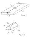
- the unitary plastics flexible mould 10 illustrated in Figures 1 and 2 is formed of a clear flexible material. It is laminar, and is formed with a straight, uniform-section bore 12 parallel to its upper planar surface and communicating with that surface through a planar cut 11 normal to the surface. In the closed configuration illustrated in Figure 1 the bore 12 is cylindrical.
- the mould 10 is flexible, and is capable of being flexed along a central portion 16 adjacent to the longitudinal bore 12, as shown in Figure 2.
- the side walls 14, 15 of the cut 11 are separated, and the bore 12 is broadened, allowing access from the exterior to the interior of the bore.
- the cross-section of the interior of the mould is thus cylindrical in its closed configuration shown in Figure 1, but key-hole-shaped in its open configuration shown in Figure 2.
- optical fibres to be spliced may have any number of cladding layers over a glass core, but for the purposes of this description it is assumed that only a primary plastics cladding layer or coating remains on each optical fibre.
- a length of 25mm at the end of each fibre is stripped mechanically of its primary cladding, to leave exposed the bare glass core which comprises at least two layers of glass of different refractive indices. These exposed ends are cleaned ultrasonically in agitated solvent, and are then each cleaved in a cleaver, the primary coating being gripped in a clamp. The exposed ends are cleaved to leave a specific length of bare glass core still exposed. The end face must be controlled to lie within one degree of the plane perpendicular to the fibre axis.
- the exposed fibre ends are cleaned in an ultrasonic cleaning tank with clean solvent, ensuring that the fibre does not touch the container.
- the cleaned, cleaved fibre ends are then transferred to a conventional fusion machine in which they are clamped by their primary coatings, ensuring that the exposed ends do not come into contact with anything.
- the fusion machine is then operated to fuse together the exposed ends, splicing the fibres together.
- the steps of stripping the primary coating, cleaning the bare fibre, cleaving the fibre end, cleaning the end once again and transferring the fibre end to the fusion machine may be performed simultaneously on both optical fibres, or alternatively may be performed in sequence.
- the spliced optical fibres are removed from the fusion machine and are located on a moulding jig (now shown) associated with the mould 10.
- the mould 10 is opened, and the spliced portion of the optical fibre is located within the bore 12 using a clean spatula, arranging the spliced portion with its primary cladding layer removed to lie centrally of the mould 10. A slight tension is applied to the fibre, to ensure that it is straight.
- a U-V curable coating material, compatible with the fibre cladding, is applied drop-wise using a syringe onto the spliced portion of the optical fibre, allowing the coating material to flow into the mould by capillary action.
- the gap between the spliced portion of the optical fibre stripped of its primary cladding and the inner wall of the bore 12 is completely filled by the coating material, the dimensions of the gap being controlled to ensure that this occurs.
- the coating material is allowed to flow over the surface of the mould 10, as shown in Figure 1 at 13, ensuring an air-tight seal.
- the region 13 of application of the coating material is slightly longer than the length of fibre whose glass core is exposed, some of the coating material being allowed to flow over the primary cladding layer.
- the mould 10 is then closed, to assume the configuration shown in Figure 1, causing the surplus material to be expelled from the interior of the mould onto the surface 13.
- the internal surface of the bore 12 is complementary to the surface of the primary cladding of the optical fibres, so that closing the mould has the effect of driving the excess material from the surface of the primary cladding, and reconstituting the exposed glass core with the coating material with a matching external diameter.
- a high intensity beam from an ultra-violet lamp is passed up and down the moulded area 13 for a period of time to cure the material.
- the excess material is then removed from the surface 13 of the mould 10 with a clean spatula, and the surface of the mould 10 is cleaned with solvent.
- the mould 10 is then opened, and the spliced optical fibres are removed from the mould, tested for any voids in the reconstituted layer, removed from the moulding jig and proof tested by applying a predetermined tension sufficient to extend the optical fibre length by a specific percentage.
- This technique may be used in the jointing of optical fibre cable, for example submarine cable.
- the individual clad optical fibres are usually accommodated in flexible tubes.
- the unit tubes are separated, and unit cutters are used to expose a length of optical fibre from each unit.
- the first section of each unit is then clamped to a jig, and then the ends of the optical fibres are cut to leave a specific length projecting from their corresponding units.
- the individual pairs of optical fibres are then spliced using the method described above, leaving them with their outer diameter reconstituted by means of the a coating material.
- a predetermined length of split unit tubing is then fitted over the spliced fibre, ensuring that the separation between the unit tubes is adjusted to give the correct amount of fibre overfeed.
- a length of heat shrink tubing, previously passed over the unit tube, is then placed evenly over the jointed area and shrunk down to hold the longitudinally-split tube and unit ends in place. This provides a nominally uniform diameter joint across the cable unit.
Landscapes
- Physics & Mathematics (AREA)
- Engineering & Computer Science (AREA)
- Chemical & Material Sciences (AREA)
- Life Sciences & Earth Sciences (AREA)
- Chemical Kinetics & Catalysis (AREA)
- General Chemical & Material Sciences (AREA)
- Geochemistry & Mineralogy (AREA)
- Materials Engineering (AREA)
- Organic Chemistry (AREA)
- General Life Sciences & Earth Sciences (AREA)
- Plasma & Fusion (AREA)
- General Physics & Mathematics (AREA)
- Optics & Photonics (AREA)
- Mechanical Coupling Of Light Guides (AREA)
Applications Claiming Priority (2)
| Application Number | Priority Date | Filing Date | Title |
|---|---|---|---|
| GB898900788A GB8900788D0 (en) | 1989-01-13 | 1989-01-13 | Splicing optical fibres |
| GB8900788 | 1989-01-13 |
Publications (2)
| Publication Number | Publication Date |
|---|---|
| EP0380207A1 true EP0380207A1 (fr) | 1990-08-01 |
| EP0380207B1 EP0380207B1 (fr) | 1993-07-07 |
Family
ID=10650014
Family Applications (1)
| Application Number | Title | Priority Date | Filing Date |
|---|---|---|---|
| EP90300189A Expired - Lifetime EP0380207B1 (fr) | 1989-01-13 | 1990-01-08 | Restitution de la gaine pour la soudure d'une fibre optique |
Country Status (6)
| Country | Link |
|---|---|
| US (1) | US5000538A (fr) |
| EP (1) | EP0380207B1 (fr) |
| JP (1) | JPH02239210A (fr) |
| AU (1) | AU624469B2 (fr) |
| DE (1) | DE69002105T2 (fr) |
| GB (2) | GB8900788D0 (fr) |
Cited By (4)
| Publication number | Priority date | Publication date | Assignee | Title |
|---|---|---|---|---|
| WO2002026652A1 (fr) * | 2000-09-25 | 2002-04-04 | Owens Corning | Matrices d'usage facile pour gainage de fils |
| WO2001046080A3 (fr) * | 1999-12-22 | 2002-06-06 | Optical Technologies Italia | Procede et dispositif de revetement d'une fibre optique |
| CN109570690A (zh) * | 2018-12-19 | 2019-04-05 | 中国原子能科学研究院 | 一种放射源包壳开孔焊接方法及放射源包壳开孔结构 |
| WO2022069011A1 (fr) * | 2020-09-29 | 2022-04-07 | Vestas Wind Systems A/S | Outil de moule |
Families Citing this family (4)
| Publication number | Priority date | Publication date | Assignee | Title |
|---|---|---|---|---|
| US5106289A (en) * | 1991-03-14 | 1992-04-21 | Hughes Aircraft Company | Elastomeric mold for optical fiber buffer |
| FR2675170B1 (fr) * | 1991-04-12 | 1993-08-06 | Fournier Christian | Dispositif de raccordement d'un ecran drainant et/ou isolant dans une tranchee. |
| GB9913264D0 (en) * | 1999-06-09 | 1999-08-04 | Raychem Sa Nv | Detent for optical fibres |
| CN1228655C (zh) * | 2001-04-03 | 2005-11-23 | 株式会社藤仓 | 平行光管透镜、纤维平行光管以及光学部件 |
Citations (2)
| Publication number | Priority date | Publication date | Assignee | Title |
|---|---|---|---|---|
| EP0019026A1 (fr) * | 1979-05-11 | 1980-11-26 | Societe Industrielle De Liaisons Electriques - Silec | Elément de câblage pour la réalisation d'éléments de câbles unitaires à fibres optiques, et procédé de fabrication |
| EP0206545A1 (fr) * | 1985-05-31 | 1986-12-30 | Corning Glass Works | Procédé et dispositif pour revêtir à nouveau des fibres optiques |
Family Cites Families (6)
| Publication number | Priority date | Publication date | Assignee | Title |
|---|---|---|---|---|
| GB2136349B (en) * | 1982-12-23 | 1985-12-04 | Bicc Plc | Optical fibre splicing |
| US4557556A (en) * | 1983-10-28 | 1985-12-10 | At&T Bell Laboratories | Method of fabricating an optical attenuator by fusion splicing of optical fibers |
| US4688882A (en) * | 1985-02-11 | 1987-08-25 | Canadian Instrumentation And Research Limited | Optical contact evanescent wave fiber optic coupler |
| US4796968A (en) * | 1986-06-02 | 1989-01-10 | The Charles Stark Draper Laboratory, Inc. | Single-mode optical-fiber directional coupler |
| JPS6296910A (ja) * | 1986-07-25 | 1987-05-06 | Nippon Telegr & Teleph Corp <Ntt> | 長尺光フアイバ心線の製造方法 |
| US4902324A (en) * | 1988-07-25 | 1990-02-20 | Corning Incorporated | Method of reproducibly making fiber optic coupler |
-
1989
- 1989-01-13 GB GB898900788A patent/GB8900788D0/en active Pending
-
1990
- 1990-01-08 GB GB9000364A patent/GB2226978B/en not_active Expired - Fee Related
- 1990-01-08 EP EP90300189A patent/EP0380207B1/fr not_active Expired - Lifetime
- 1990-01-08 DE DE90300189T patent/DE69002105T2/de not_active Expired - Fee Related
- 1990-01-10 AU AU47848/90A patent/AU624469B2/en not_active Ceased
- 1990-01-11 US US07/463,272 patent/US5000538A/en not_active Expired - Fee Related
- 1990-01-12 JP JP2003673A patent/JPH02239210A/ja active Pending
Patent Citations (2)
| Publication number | Priority date | Publication date | Assignee | Title |
|---|---|---|---|---|
| EP0019026A1 (fr) * | 1979-05-11 | 1980-11-26 | Societe Industrielle De Liaisons Electriques - Silec | Elément de câblage pour la réalisation d'éléments de câbles unitaires à fibres optiques, et procédé de fabrication |
| EP0206545A1 (fr) * | 1985-05-31 | 1986-12-30 | Corning Glass Works | Procédé et dispositif pour revêtir à nouveau des fibres optiques |
Non-Patent Citations (1)
| Title |
|---|
| PATENT ABSTRACTS OF JAPAN * |
Cited By (5)
| Publication number | Priority date | Publication date | Assignee | Title |
|---|---|---|---|---|
| WO2001046080A3 (fr) * | 1999-12-22 | 2002-06-06 | Optical Technologies Italia | Procede et dispositif de revetement d'une fibre optique |
| WO2002026652A1 (fr) * | 2000-09-25 | 2002-04-04 | Owens Corning | Matrices d'usage facile pour gainage de fils |
| US6610146B1 (en) | 2000-09-25 | 2003-08-26 | Owens-Corning Fiberglas Technology, Inc. | Easy threading wirecoating dies |
| CN109570690A (zh) * | 2018-12-19 | 2019-04-05 | 中国原子能科学研究院 | 一种放射源包壳开孔焊接方法及放射源包壳开孔结构 |
| WO2022069011A1 (fr) * | 2020-09-29 | 2022-04-07 | Vestas Wind Systems A/S | Outil de moule |
Also Published As
| Publication number | Publication date |
|---|---|
| GB8900788D0 (en) | 1989-03-08 |
| GB2226978B (en) | 1993-01-27 |
| JPH02239210A (ja) | 1990-09-21 |
| US5000538A (en) | 1991-03-19 |
| DE69002105T2 (de) | 1994-01-13 |
| GB2226978A (en) | 1990-07-18 |
| GB9000364D0 (en) | 1990-03-07 |
| DE69002105D1 (de) | 1993-08-12 |
| EP0380207B1 (fr) | 1993-07-07 |
| AU4784890A (en) | 1990-07-19 |
| AU624469B2 (en) | 1992-06-11 |
Similar Documents
| Publication | Publication Date | Title |
|---|---|---|
| US11347014B2 (en) | Optical fiber fan-out assembly with ribbonized interface for mass fusion splicing, and fabrication method | |
| EP0206545B1 (fr) | Procédé et dispositif pour revêtir à nouveau des fibres optiques | |
| US6779931B2 (en) | Optical fiber connecting element and alignment sleeve | |
| US20100209052A1 (en) | Fiber optic connector assembly and method for venting gas inside a fiber optic connector sub-assembly | |
| KR880004334A (ko) | 광파이버의 접속방법 | |
| JP2533014Y2 (ja) | リボン状多心光ファイバの永久接続器 | |
| EP0380207B1 (fr) | Restitution de la gaine pour la soudure d'une fibre optique | |
| CA1248312A (fr) | Procede et appareillage pour l'enrobage des epissures de fibres optiques | |
| CN102405429A (zh) | 在光纤电缆上直接模塑套圈的方法 | |
| US11808983B2 (en) | Multi-fiber splice protector with compact splice-on furcation housing | |
| CA1311349C (fr) | Methode d'epissage pour fibres | |
| JPS6235644B2 (fr) | ||
| EP0896235B1 (fr) | Virole d'un connecteur à fibre optique | |
| JPS59109015A (ja) | 光フアイバの補修方法及びその装置 | |
| US4678272A (en) | Optical fiber splice | |
| US4762580A (en) | Optical fibre splice reinstatement sheathing | |
| EP3480637B1 (fr) | Systèmes et techniques permettant d'épissage simultanément des câbles à ruban en fibre optique ayant différents espacements noyau à noyau | |
| JPH0560842B2 (fr) | ||
| JPS61208009A (ja) | 細長い部材の配置方法 | |
| JP2687145B2 (ja) | 光ファイバ接続具の製造方法 | |
| EP0085528A2 (fr) | Epissure pour fibres optiques | |
| JP2023030813A (ja) | 光コンバイナの製造方法 | |
| JPH05157929A (ja) | 光ファイバ接続部の被覆方法 | |
| JPH02187707A (ja) | 光ファイバ融着接続部のモールド成形補強方法 |
Legal Events
| Date | Code | Title | Description |
|---|---|---|---|
| PUAI | Public reference made under article 153(3) epc to a published international application that has entered the european phase |
Free format text: ORIGINAL CODE: 0009012 |
|
| AK | Designated contracting states |
Kind code of ref document: A1 Designated state(s): DE FR IT NL |
|
| 17P | Request for examination filed |
Effective date: 19900706 |
|
| 17Q | First examination report despatched |
Effective date: 19920403 |
|
| GRAA | (expected) grant |
Free format text: ORIGINAL CODE: 0009210 |
|
| AK | Designated contracting states |
Kind code of ref document: B1 Designated state(s): DE FR IT NL |
|
| ITF | It: translation for a ep patent filed | ||
| ET | Fr: translation filed | ||
| REF | Corresponds to: |
Ref document number: 69002105 Country of ref document: DE Date of ref document: 19930812 |
|
| PLBE | No opposition filed within time limit |
Free format text: ORIGINAL CODE: 0009261 |
|
| STAA | Information on the status of an ep patent application or granted ep patent |
Free format text: STATUS: NO OPPOSITION FILED WITHIN TIME LIMIT |
|
| 26N | No opposition filed | ||
| PGFP | Annual fee paid to national office [announced via postgrant information from national office to epo] |
Ref country code: DE Payment date: 19991231 Year of fee payment: 11 |
|
| PGFP | Annual fee paid to national office [announced via postgrant information from national office to epo] |
Ref country code: FR Payment date: 20000112 Year of fee payment: 11 |
|
| PGFP | Annual fee paid to national office [announced via postgrant information from national office to epo] |
Ref country code: NL Payment date: 20000131 Year of fee payment: 11 |
|
| PG25 | Lapsed in a contracting state [announced via postgrant information from national office to epo] |
Ref country code: NL Free format text: LAPSE BECAUSE OF NON-PAYMENT OF DUE FEES Effective date: 20010801 |
|
| PG25 | Lapsed in a contracting state [announced via postgrant information from national office to epo] |
Ref country code: FR Free format text: LAPSE BECAUSE OF NON-PAYMENT OF DUE FEES Effective date: 20010928 |
|
| NLV4 | Nl: lapsed or anulled due to non-payment of the annual fee |
Effective date: 20010801 |
|
| PG25 | Lapsed in a contracting state [announced via postgrant information from national office to epo] |
Ref country code: DE Free format text: LAPSE BECAUSE OF NON-PAYMENT OF DUE FEES Effective date: 20011101 |
|
| REG | Reference to a national code |
Ref country code: FR Ref legal event code: ST |
|
| PG25 | Lapsed in a contracting state [announced via postgrant information from national office to epo] |
Ref country code: IT Free format text: LAPSE BECAUSE OF NON-PAYMENT OF DUE FEES Effective date: 20050108 |