EP0380218B1 - Reihe von mehreren Einlassventilen für eine einzelne Öffnung - Google Patents
Reihe von mehreren Einlassventilen für eine einzelne Öffnung Download PDFInfo
- Publication number
- EP0380218B1 EP0380218B1 EP90300371A EP90300371A EP0380218B1 EP 0380218 B1 EP0380218 B1 EP 0380218B1 EP 90300371 A EP90300371 A EP 90300371A EP 90300371 A EP90300371 A EP 90300371A EP 0380218 B1 EP0380218 B1 EP 0380218B1
- Authority
- EP
- European Patent Office
- Prior art keywords
- valve
- duct
- valves
- area
- poppet
- Prior art date
- Legal status (The legal status is an assumption and is not a legal conclusion. Google has not performed a legal analysis and makes no representation as to the accuracy of the status listed.)
- Expired - Lifetime
Links
- 238000002485 combustion reaction Methods 0.000 claims description 14
- 239000012530 fluid Substances 0.000 claims description 3
- 230000000295 complement effect Effects 0.000 claims description 2
- 230000008901 benefit Effects 0.000 description 2
- 238000010586 diagram Methods 0.000 description 2
- 238000009792 diffusion process Methods 0.000 description 2
- 230000006698 induction Effects 0.000 description 2
- 238000007789 sealing Methods 0.000 description 2
- 230000007704 transition Effects 0.000 description 2
- 230000001133 acceleration Effects 0.000 description 1
- 230000003993 interaction Effects 0.000 description 1
- 238000004519 manufacturing process Methods 0.000 description 1
- 238000000926 separation method Methods 0.000 description 1
- 238000011144 upstream manufacturing Methods 0.000 description 1
Images
Classifications
-
- F—MECHANICAL ENGINEERING; LIGHTING; HEATING; WEAPONS; BLASTING
- F01—MACHINES OR ENGINES IN GENERAL; ENGINE PLANTS IN GENERAL; STEAM ENGINES
- F01L—CYCLICALLY OPERATING VALVES FOR MACHINES OR ENGINES
- F01L1/00—Valve-gear or valve arrangements, e.g. lift-valve gear
- F01L1/26—Valve-gear or valve arrangements, e.g. lift-valve gear characterised by the provision of two or more valves operated simultaneously by same transmitting-gear; peculiar to machines or engines with more than two lift-valves per cylinder
- F01L1/265—Valve-gear or valve arrangements, e.g. lift-valve gear characterised by the provision of two or more valves operated simultaneously by same transmitting-gear; peculiar to machines or engines with more than two lift-valves per cylinder peculiar to machines or engines with three or more intake valves per cylinder
-
- F—MECHANICAL ENGINEERING; LIGHTING; HEATING; WEAPONS; BLASTING
- F01—MACHINES OR ENGINES IN GENERAL; ENGINE PLANTS IN GENERAL; STEAM ENGINES
- F01L—CYCLICALLY OPERATING VALVES FOR MACHINES OR ENGINES
- F01L1/00—Valve-gear or valve arrangements, e.g. lift-valve gear
- F01L1/12—Transmitting gear between valve drive and valve
- F01L1/14—Tappets; Push rods
- F01L1/143—Tappets; Push rods for use with overhead camshafts
-
- F—MECHANICAL ENGINEERING; LIGHTING; HEATING; WEAPONS; BLASTING
- F02—COMBUSTION ENGINES; HOT-GAS OR COMBUSTION-PRODUCT ENGINE PLANTS
- F02F—CYLINDERS, PISTONS OR CASINGS, FOR COMBUSTION ENGINES; ARRANGEMENTS OF SEALINGS IN COMBUSTION ENGINES
- F02F1/00—Cylinders; Cylinder heads
- F02F1/24—Cylinder heads
- F02F1/42—Shape or arrangement of intake or exhaust channels in cylinder heads
- F02F1/4214—Shape or arrangement of intake or exhaust channels in cylinder heads specially adapted for four or more valves per cylinder
- F02F1/4221—Shape or arrangement of intake or exhaust channels in cylinder heads specially adapted for four or more valves per cylinder particularly for three or more inlet valves
-
- F—MECHANICAL ENGINEERING; LIGHTING; HEATING; WEAPONS; BLASTING
- F01—MACHINES OR ENGINES IN GENERAL; ENGINE PLANTS IN GENERAL; STEAM ENGINES
- F01L—CYCLICALLY OPERATING VALVES FOR MACHINES OR ENGINES
- F01L3/00—Lift-valve, i.e. cut-off apparatus with closure members having at least a component of their opening and closing motion perpendicular to the closing faces; Parts or accessories thereof
- F01L2003/25—Valve configurations in relation to engine
- F01L2003/251—Large number of valves, e.g. five or more
-
- F—MECHANICAL ENGINEERING; LIGHTING; HEATING; WEAPONS; BLASTING
- F02—COMBUSTION ENGINES; HOT-GAS OR COMBUSTION-PRODUCT ENGINE PLANTS
- F02B—INTERNAL-COMBUSTION PISTON ENGINES; COMBUSTION ENGINES IN GENERAL
- F02B2275/00—Other engines, components or details, not provided for in other groups of this subclass
- F02B2275/10—Diamond configuration of valves in cylinder heads
-
- F—MECHANICAL ENGINEERING; LIGHTING; HEATING; WEAPONS; BLASTING
- F02—COMBUSTION ENGINES; HOT-GAS OR COMBUSTION-PRODUCT ENGINE PLANTS
- F02B—INTERNAL-COMBUSTION PISTON ENGINES; COMBUSTION ENGINES IN GENERAL
- F02B2275/00—Other engines, components or details, not provided for in other groups of this subclass
- F02B2275/20—SOHC [Single overhead camshaft]
-
- F—MECHANICAL ENGINEERING; LIGHTING; HEATING; WEAPONS; BLASTING
- F02—COMBUSTION ENGINES; HOT-GAS OR COMBUSTION-PRODUCT ENGINE PLANTS
- F02F—CYLINDERS, PISTONS OR CASINGS, FOR COMBUSTION ENGINES; ARRANGEMENTS OF SEALINGS IN COMBUSTION ENGINES
- F02F1/00—Cylinders; Cylinder heads
- F02F1/24—Cylinder heads
- F02F2001/244—Arrangement of valve stems in cylinder heads
- F02F2001/247—Arrangement of valve stems in cylinder heads the valve stems being orientated in parallel with the cylinder axis
Definitions
- This invention relates to an intake valve array for use in a four cycle internal combustion engine to increase volumetric efficiency, and specifically to a multiple poppet intake valve array that uses three or more poppet valve bodies for opening and sealing a single intake duct.
- the sum of the circumferential distances of the valve bodies are specifically determined to achieve optimum lift requirements earlier in the intake valve event, thus extending the duration of optimum valve opening area relative to the duct cross sectional area.
- the purpose of the invention is to quantitatively increase the duration period of optimum available intake valve open area (circumference times lift) of a single intake duct to enhance optimum charge flow into the combustion chamber during the intake event resulting in greater volumetric efficiency when compared with the duration of maximum valve open area available with one or two conventional intake poppet valves.
- each intake duct is serviced by one intake poppet valve.
- the cross sectional area of the duct and the area of the valve body at maximum lift are generally matched to prevent impedance of the charge velocity when the valve is fully open. Since the correct maximum valve open area is the valve body circumference times maximum lift, conventional valve lift distances exceeding 0.762 cm (.300 inches) are employed. Such lift distances encroach the mechanical limits of the cam lobe profile and its valve train components due to time constraints during the intake event. The result is that maximum valve opening is achieved at only one limited instantaneous position over the entire intake events' duration at the cam lobe.
- GB A 2 058 919 discloses a multiple poppet valve array for use with a single intake duct in a four cylinder internal combustion engine. This document is primarily aimed at providing an elliptical combustion chamber for an internal combustion engine.
- a multiple poppet valve array for use with a single intake duct in a four cycle internal combustion engine comprising three or more poppet valves; an engine cylinder; a cylinder head having a single intake duct in fluid communication with a combustion chamber, the intake duct having three or more apertures opening into said engine cylinder, the apertures including poppet valve seats about their perimeter for seating the three or more poppet valves and sized so as to complement the charge flow characteristics of the duct, and means for opening and closing each of the poppet valves in communication with the poppet valves characterised in that the total aperture area of the cylinder substantially matches the cross-sectional area of the single intake duct and the sum of circumferences of the apertures is greater than the circumference of the duct by a factor of 1.4 or more.
- each poppet valve body and each respective aperture at the centreline of the seat is equal to each other.
- the number of poppet valves and apertures is four and the circumferences of the valve bodies exceeds the circumference of the duct by a factor of 2.
- the lifting and closing means are sized to a lift distance at least sufficient to optimize duration during the intake event wherein the total valve open area is generally equal to the total port area.
- valve lift requirement for optimum flow and duration when compared with a single valve servicing the duct is reduced by a factor that equals the reciprocal of the square root of the number of valves employed.
- Three or more annular intake poppet valves are used with a single substantially annular intake duct, the valves providing opening and sealing of the duct within multiple annular ports that open into the engine cylinder.
- the poppet valves are disposed about the axis of a single port.
- the diameter of each valve face is predetermined in size such that the sum total of the circumferential distances of the poppet valves exceeds the circumference of the duct by at least a factor of 1.4 or more, reducing maximum valve lift distance required to match or approximate duct cross sectional area.
- the sum total of the valve array generally maintains equality to the area of the duct.
- the single duct transitions into an interface of multiple ports (branching) opening into the engine cylinder to accommodate the multiple valve seats and the respective ports for the multiple poppet valve array, ensuring that the duct cross sectional area, when compared with the sum total of the multiple valve seat port areas, is generally equal in order to prevent charge flow impedance or diffusion.
- Each of the valves in the array is opened and closed in a conventional manner using spring tension and a cam and cam lobes.
- the duration of maximum charge flowability is greatly enhanced because of the increased valve circumference available.
- reduced lift requirements in combination with the valve array achieve maximum duct charge flowability earlier in the valve event.
- Lower optimum valve lift requirements result in the valve array reaching their optimum lift position earlier during acceleration upon a conventional cam profile resulting in an extended duration of optimum valve open area (circumference times lift) during the intake event.
- the important benefits of this invention occur because of the extended time of maximum flowability available for the intake charge flow into the engine cylinder from a single duct, thus allowing for greater volumetric efficiency achievement during the intake event, while at the same time maintaining the necessary predetermined available area for flow through the ports into the engine cylinder.
- the required maximum lift distance for each valve can be reduced while improved per unit time optimum flow into the engine cylinder occurs.
- the use of multiple poppet valves for a single duct allows the physical dimensions of the duct diameter and area, the valve diameters and seat areas, and the valve circumferences times lift (valve open areas) to be optimized to minimize charge flow impedance for an increased duration period.
- Another object of this invention is to provide an intake valve array that allows the engine designer to improve particular cam lobe parameters such as to open the intake valve array later as compared to conventional valve opening requirements, thus resulting in improved charge filling without charge cross over (overlap).
- Yet another object of this invention is to provide a valve array for use in an internal combustion engine which may also function during the exhaust cycle as an exhaust valve array.
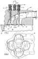
- Figure 1 is a side elevational view in cross section showing a preferred embodiment of the invention.
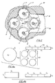
- Figure 2 is a top plan view in cross section showing the invention.
- Figure 3 is a bottom plan view of the invention.
- Figure 4 is a diagram with geometrical figures useful in discussing certain relative dimensions employed in the invention.
- four intake poppet valves are symetrically disposed about the axis of a single duct.
- the invention is shown generally at 10 comprised of four intake poppet valves 11 having stems 12 connected through valve guides 13, each of said valves 11 being disposed in fluid communication with the single intake duct 14 which leads from the charge source 15 to the engine cylinder 16.
- the inlet ports 17 to the engine cylinder 16 includes a wall surface 18 that houses a valve seat for each of the valves 11.
- Each of the valves 11 is opened through a cam 19 pushing disk 20 that is in communication with each of the valves stems 12.
- the valves 11 are sealed shut by the action of springs 21 connected to each valve stem 12 in a conventional manner.
- the cylinder head 22 is connected to engine block 23 that houses the engine cylinder 16.
- a poppet exhaust valve (not shown) would communicate with the engine cylinder 16 in a conventional manner.
- the area of the intake duct 14 is predetermined in size such that the combined total area of the ports 17 are substantially equal to the cross sectional area of the duct 14. With multiple equal area valves 11 (three or more), the circumferential distance of the sum total of the valves 11 and therefore the ports 17 is generally 1.4 or more times the circumference of a single valve conventionally used across a single port opening in the cylinder head.
- the preferred embodiment utilizes four poppet intake valves 11 as shown in Figure 1 wherein each valve diameter is determined in size relative to the diameter of the duct 14 to achieve comparable seat area to duct area and valve open area (circumference times lift).
- a tapered somewhat conical wall segment 22A is employed in the region of transition of the charge flow into the ports 17.
- FIGS 1, 2 and 3 show the relationship and location of the valves 11 relative to the intake duct 14 diameter as previously described. Note that the valve stems 12 are disposed symetrically about the center axis of the duct 14 in the preferred embodiment, with the valve stems 12 being substantially near the perimeter wall of the duct 14.
- Each port 17 within cylinder head 22 includes a valve seat 18 for each poppet valve 11 to ensure the proper seal across the ports.
- the cylinder head body 22 provides the seating surfaces 18 for the poppet valves 11.
- the ports 17 would be cast with the cylinder head 22.
- the duct 14 opening could also be constructed using a plate having the port apertures and seats and which would be inserted across the duct opening (with or without segment 22A).
- Figures 4a and 4b show a diagram having geometrical figures in order to compare the valve open areas (circumferences times lift) to the duct area and the port (seat) areas.
- the area A1 of the duct is generally equal to the total areas of the ports A2 and the area of the open valves A3 at optimum lift.
- Figure 4b shows a comparison of the lift distance 1c required for a single valve with circumference Cc to achieve the same open area as four valves having circumferences Cv and a greatly reduced lift distance 1v.
- the duct area, the total multiple port (seat) areas, and the optimum valve open areas are comparable in size maintaining constant velocity and interflument consistency resulting in high charge flow velocity, while the duration of the optimum charge flow area results in greater charge flow volume into the cylinder during the intake event.
- the required lift distance to achieve equal valve open area is 1.016 cm (.400 inches).
- the lift required to achieve equal valve open area is 0.508 cm (.200 inches). This means that when the four valves reach 0.508 cm (.200 inches) lift, they are providing an open area that equals the duct area, the theoretical optimum. Because the four valves reach 0.508 cm (.200 inches) lift much earlier in the intake cycle than a single valve reaches 1.016 cm (.400 inches), duration at optimum area/flow is considerably longer with four valves resulting in improved volumetric efficiency.
- the multiple ports for each duct can be moulded in a conventional way or using an existent cylinder head, a plate like member having the port or partial port openings can be affixed across each duct opening.
- multiple valves may be opened in unison or sequentially.
Landscapes
- Engineering & Computer Science (AREA)
- Mechanical Engineering (AREA)
- General Engineering & Computer Science (AREA)
- Chemical & Material Sciences (AREA)
- Combustion & Propulsion (AREA)
- Valve-Gear Or Valve Arrangements (AREA)
- Cylinder Crankcases Of Internal Combustion Engines (AREA)
Claims (6)
- Anordnung aus mehreren Tellerventilen zur Verwendung in einem einzigen Ansaugkanal (14) eines Viertakt-Verbrennungsmotors
mit drei oder mehr als drei Tellerventilen (11);
mit einem Zylinder (16);
mit einem Zylinderkopf (22), der einen einzigen Ansaugkanal (14) in Strömungsverbindung mit einer Verbrennungskammer hat, wobei der Ansaugkanal (14) drei oder mehr als drei Öffnungen (17) hat, die in den Zylinder des Motors münden, und die Öffnungen an ihrem Umfang Ventilsitze für die drei oder mehr als drei Tellerventile (11) haben und so bemessen sind, dass sie die Strömungseigenschaften des Ansaugkanals (14) beim Ladevorgang ergänzen, und mit Mitteln (19, 20) zum Öffnen und Schließen eines jeden der Tellerventile, die mit den Tellerventilen in Verbindung stehen,
dadurch gekennzeichnet, dass der gesamte Öffnungsquerschnitt des Zylinders (16) im wesentlichen mit der Querschnittsfläche des einzigen Ansaugkanals (14) übereinstimmt und die Summe der Umfänge der Öffnungen (17) um einen Faktor von 1,4 oder mehr größer ist als der Umfang des Ansaugkanals (14). - Anordnung aus mehreren Tellerventilen nach Anspruch 1, in welcher die Querschnittsflächen eines jeden Ventilkörpers und jeder zugehörigen Öffnung (17) gemessen an der Mittellinie des Ventilsitzes (18) einander gleich sind.
- Anordnung aus mehreren Tellerventilen nach Anspruch 1 oder 2, in welcher die Anzahl der Tellerventile (11) und der Öffnungen (17) vier ist.
- Anordnung aus mehreren Tellerventilen nach Anspruch 3, dadurch gekennzeichnet, dass die Umfänge der Ventilkörper zusammengenommen um einen Faktor 2 größer sind als der Umfang des Ansaugkanals.
- Anordnung aus mehreren Tellerventilen nach einem der vorstehenden Ansprüche, dadurch gekennzeichnet, dass die Mittel (19, 20) zum Öffnen und Schließen so bemessen sind, dass sich ein Ventilhub ergibt, der zumindest ausreicht, um jene Zeitspanne während des Ansaugtaktes zu optimieren, in welcher der gesamte vom offenen Ventil freigegebene Querschnitt gleich dem gesamten Querschnitt der Öffnung (17) ist.
- Anordnung aus mehreren Tellerventilen nach Anspruch 5, dadurch gekennzeichnet, dass der - verglichen mit einem durch nur ein einziges Ventil bedienten Ansaugkanal - für optimale Strömung und Dauer erforderliche Ventilhub um einen Faktor herabgesetzt ist, welcher dem Kehrwert der Quadratwurzel aus der Anzahl der in der Anordnung vorhandenen Ventile gleich ist.
Applications Claiming Priority (2)
| Application Number | Priority Date | Filing Date | Title |
|---|---|---|---|
| US299987 | 1989-01-23 | ||
| US07/299,987 US4907554A (en) | 1989-01-23 | 1989-01-23 | Multiple intake poppet valve array for a single port |
Publications (2)
| Publication Number | Publication Date |
|---|---|
| EP0380218A1 EP0380218A1 (de) | 1990-08-01 |
| EP0380218B1 true EP0380218B1 (de) | 1993-12-08 |
Family
ID=23157179
Family Applications (1)
| Application Number | Title | Priority Date | Filing Date |
|---|---|---|---|
| EP90300371A Expired - Lifetime EP0380218B1 (de) | 1989-01-23 | 1990-01-12 | Reihe von mehreren Einlassventilen für eine einzelne Öffnung |
Country Status (4)
| Country | Link |
|---|---|
| US (1) | US4907554A (de) |
| EP (1) | EP0380218B1 (de) |
| JP (1) | JP2672167B2 (de) |
| DE (1) | DE69004981T2 (de) |
Families Citing this family (4)
| Publication number | Priority date | Publication date | Assignee | Title |
|---|---|---|---|---|
| AU657699B2 (en) * | 1991-08-30 | 1995-03-23 | Caterpillar Inc. | Modified cylinder head |
| AU648647B2 (en) * | 1991-09-03 | 1994-04-28 | Caterpillar Inc. | Valve actuation device |
| DE4413508A1 (de) * | 1994-04-19 | 1995-10-26 | Opel Adam Ag | Ventiltrieb für zumindest zwei gleichzeitig zu betätigende Hubventile für den Gaswechsel einer Brennkraftmaschine |
| JPH08200075A (ja) * | 1995-01-30 | 1996-08-06 | Toyota Motor Corp | 内燃機関の燃焼室 |
Family Cites Families (8)
| Publication number | Priority date | Publication date | Assignee | Title |
|---|---|---|---|---|
| JPS5638520A (en) * | 1979-09-04 | 1981-04-13 | Honda Motor Co Ltd | Four-cycle internal combustion engine |
| JPS5641419A (en) * | 1979-09-10 | 1981-04-18 | Honda Motor Co Ltd | Four-cycle internal combustion engine |
| JPH0658088B2 (ja) * | 1984-03-15 | 1994-08-03 | ヤマハ発動機株式会社 | 4サイクル内燃機関の吸気装置 |
| US4617896A (en) * | 1985-03-14 | 1986-10-21 | Yamaha Hatsudoki Kabushiki Kaisha | Internal combustion engine having three intake valves per cylinder |
| US4667636A (en) * | 1985-03-22 | 1987-05-26 | Toyota Jidosha Kabushiki Kaisha | Fuel injection type internal combustion engine |
| GB8605619D0 (en) * | 1986-03-07 | 1986-04-16 | Valentine B C | Poppet valve assemblies |
| JPS62228622A (ja) * | 1986-03-31 | 1987-10-07 | Yamaha Motor Co Ltd | エンジンの吸気装置 |
| US4765287A (en) * | 1987-11-02 | 1988-08-23 | Taylor Bill A | Slide valve apparatus for internal combustion engine |
-
1989
- 1989-01-23 US US07/299,987 patent/US4907554A/en not_active Expired - Fee Related
-
1990
- 1990-01-12 DE DE69004981T patent/DE69004981T2/de not_active Expired - Fee Related
- 1990-01-12 EP EP90300371A patent/EP0380218B1/de not_active Expired - Lifetime
- 1990-01-22 JP JP2012393A patent/JP2672167B2/ja not_active Expired - Lifetime
Also Published As
| Publication number | Publication date |
|---|---|
| DE69004981D1 (de) | 1994-01-20 |
| EP0380218A1 (de) | 1990-08-01 |
| JPH02271029A (ja) | 1990-11-06 |
| US4907554A (en) | 1990-03-13 |
| JP2672167B2 (ja) | 1997-11-05 |
| DE69004981T2 (de) | 1994-06-23 |
Similar Documents
| Publication | Publication Date | Title |
|---|---|---|
| US4836154A (en) | Poppet valve assembly with apertures | |
| US5797368A (en) | Reciprocating piston internal combustion engine having at least one cylinder | |
| US4606308A (en) | Engine cylinder intake port | |
| US4827883A (en) | Variable swirl inlet port | |
| US5081965A (en) | Intake valve for internal combustion engine | |
| US4831976A (en) | Engine with valve seat inserts and method of retaining | |
| US5558061A (en) | Engine cylinder intake port | |
| US4539954A (en) | Selective asymmetric swirl intake port | |
| US5826560A (en) | Engine combustion chamber and method of operation | |
| US4907554A (en) | Multiple intake poppet valve array for a single port | |
| US4106466A (en) | Engine valve with recessed seat and annular groove | |
| CA1334500C (en) | Multivalve cylinder head | |
| US5005538A (en) | Extended circumference intake poppet valve system for opening and sealing a single valve seat | |
| CN106948892A (zh) | 一种旋转开合型配气机构 | |
| AU604297B2 (en) | Internal combustion engine intake valve | |
| EP0725890B1 (de) | Zylinderkopf für viertakt-brennkraftmaschinen | |
| US20200308998A1 (en) | Poppet valve for internal combustion engine | |
| US4572117A (en) | Valve arrangement for an internal combustion engine | |
| JPH07102915A (ja) | 4サイクルエンジン | |
| US20020117131A1 (en) | Poly valve system for internal combustion engines | |
| US4615309A (en) | Valve actuating mechanism for internal combustion engine | |
| US5277160A (en) | Internal combustion engine with dual intake passages servicing a single intake valve | |
| US4964384A (en) | Tornado engine | |
| US6510837B1 (en) | Induction system for engine | |
| US6659059B1 (en) | Variable displacement valve seat for internal combustion engines |
Legal Events
| Date | Code | Title | Description |
|---|---|---|---|
| PUAI | Public reference made under article 153(3) epc to a published international application that has entered the european phase |
Free format text: ORIGINAL CODE: 0009012 |
|
| AK | Designated contracting states |
Kind code of ref document: A1 Designated state(s): DE FR GB IT SE |
|
| 17P | Request for examination filed |
Effective date: 19910201 |
|
| 17Q | First examination report despatched |
Effective date: 19910905 |
|
| GRAA | (expected) grant |
Free format text: ORIGINAL CODE: 0009210 |
|
| AK | Designated contracting states |
Kind code of ref document: B1 Designated state(s): DE FR GB IT SE |
|
| PG25 | Lapsed in a contracting state [announced via postgrant information from national office to epo] |
Ref country code: IT Free format text: LAPSE BECAUSE OF FAILURE TO SUBMIT A TRANSLATION OF THE DESCRIPTION OR TO PAY THE FEE WITHIN THE PRE;WARNING: LAPSES OF ITALIAN PATENTS WITH EFFECTIVE DATE BEFORE 2007 MAY HAVE OCCURRED AT ANY TIME BEFORE 2007. THE CORRECT EFFECTIVE DATE MAY BE DIFFERENT FROM THE ONE RECORDED.SCRIBED TIME-LIMIT Effective date: 19931208 Ref country code: SE Effective date: 19931208 |
|
| REF | Corresponds to: |
Ref document number: 69004981 Country of ref document: DE Date of ref document: 19940120 |
|
| ET | Fr: translation filed | ||
| PLBE | No opposition filed within time limit |
Free format text: ORIGINAL CODE: 0009261 |
|
| STAA | Information on the status of an ep patent application or granted ep patent |
Free format text: STATUS: NO OPPOSITION FILED WITHIN TIME LIMIT |
|
| 26N | No opposition filed | ||
| PGFP | Annual fee paid to national office [announced via postgrant information from national office to epo] |
Ref country code: FR Payment date: 20010118 Year of fee payment: 12 Ref country code: DE Payment date: 20010118 Year of fee payment: 12 |
|
| PGFP | Annual fee paid to national office [announced via postgrant information from national office to epo] |
Ref country code: GB Payment date: 20010122 Year of fee payment: 12 |
|
| REG | Reference to a national code |
Ref country code: GB Ref legal event code: IF02 |
|
| PG25 | Lapsed in a contracting state [announced via postgrant information from national office to epo] |
Ref country code: GB Free format text: LAPSE BECAUSE OF NON-PAYMENT OF DUE FEES Effective date: 20020112 |
|
| PG25 | Lapsed in a contracting state [announced via postgrant information from national office to epo] |
Ref country code: DE Free format text: LAPSE BECAUSE OF NON-PAYMENT OF DUE FEES Effective date: 20020801 |
|
| GBPC | Gb: european patent ceased through non-payment of renewal fee |
Effective date: 20020112 |
|
| PG25 | Lapsed in a contracting state [announced via postgrant information from national office to epo] |
Ref country code: FR Free format text: LAPSE BECAUSE OF NON-PAYMENT OF DUE FEES Effective date: 20020930 |
|
| REG | Reference to a national code |
Ref country code: FR Ref legal event code: ST |