EP0380231A2 - A whip antenna for use in vehicles - Google Patents
A whip antenna for use in vehicles Download PDFInfo
- Publication number
- EP0380231A2 EP0380231A2 EP90300465A EP90300465A EP0380231A2 EP 0380231 A2 EP0380231 A2 EP 0380231A2 EP 90300465 A EP90300465 A EP 90300465A EP 90300465 A EP90300465 A EP 90300465A EP 0380231 A2 EP0380231 A2 EP 0380231A2
- Authority
- EP
- European Patent Office
- Prior art keywords
- antenna
- antenna element
- coupling member
- attachment base
- screw
- Prior art date
- Legal status (The legal status is an assumption and is not a legal conclusion. Google has not performed a legal analysis and makes no representation as to the accuracy of the status listed.)
- Granted
Links
Images

Classifications
-
- H—ELECTRICITY
- H01—ELECTRIC ELEMENTS
- H01Q—ANTENNAS, i.e. RADIO AERIALS
- H01Q1/00—Details of, or arrangements associated with, antennas
- H01Q1/12—Supports; Mounting means
- H01Q1/1207—Supports; Mounting means for fastening a rigid aerial element
- H01Q1/1214—Supports; Mounting means for fastening a rigid aerial element through a wall
Definitions
- the present invention relates to whip antennas mounted on vehicles such as automobiles, etc.
- antennas used as automobile radio antennas There are various structural types of antennas used as automobile radio antennas. Among these, one type of antenna which can be manufactured at low cost while still providing sufficient radio reception (which is a minimum requirement for such antennas) is a single-length whip antenna.
- a single-length whip antenna usually includes a single, continuous rod-form conductive part which more or less matches a quarter wavelength of the FM wave band. When mounted on a vehicle, such antenna remains exposed on the outside of the vehicle body.
- high tensile materials having high recoil strength such as high tensile strength stainless steel etc. are used to form such an antenna so that the antenna will be able to withstand loads applied by obstructions during operation of the vehicle and/or when the vehicle is washed.
- the whip antenna When the whip antenna is installed on a vehicle body in the assembly line, the antenna tends to occupy a relatively large space above the vehicle body. Thus, when vehicles having such an antenna installed thereon are transported, a great deal of space is wasted in order to accommodate the antenna. For this reason, the whip antennas are usually removable from the vehicle body (that is, from an attachment base which has been mounted to the vehicle body wall) via screws, etc. so as to save maximum amount of space and facilitate the transport of more vehicles.
- Such antennas are, however, likely to suffer problems in that the material used to form the whip material must have a high tensile strength. However, such material is difficult to work with, and thus, it is difficult for example to cut threads thereon. As a result, it is also difficult to screw-couple such an antenna to the attachment base in an "as is" condition.
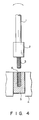
- a structure like that shown in Fig. 4 has been employed in the prior art. Specifically, a joint 2 is attached to the base end of a whip antenna element 1, and a male screw 3 connected to this joint 2 is screwed into a female screw 6 formed in a coupling element 5 of an attachment base 4.
- a material having a tensile strength lower than that of the whip antenna element 1 is used to form the joint 2 in order to secure good workability.
- such material must be thoroughly sufficient in terms of strength. Accordingly, the manufacturing costs tend to be high.
- the object of the present invention is to provide a whip antenna for use in vehicles wherein a rod-form antenna element can be screw-coupled (or removably coupled) to an attachment base and the strength of the coupling section is great enough to avoid the danger of breakage, etc., even if the load of the antenna should be concentrated at the coupling section.
- the present invention adopts the following structure:
- a coupling member having a female screw formed on its inside circumferential surface is fastened to a rod-form antenna element near the lower end thereof.
- the coupling member on the rod-form antenna is prevented moving downwardly (toward the vehicle body) so that it cannot move toward the lower end of the antenna element from a certain point on the antenna element.
- the coupling member thus mounted on the antenna element is screw-coupled to an attachment base which is mounted on a vehicle body. Screw-coupling is accomplished by inserting the lower end of the antenna element into a hole formed in the attachment base and then screwing the female screw of the coupling member to a male screw installed in the attachment base.
- the base portion of the rod-form antenna element made of a highly rigid material may be used directly “as is “ as a coupling core (without the necessity of a joint as conventionally required).
- a base portion can be directly coupled to the attachment base.
- the intrinsic high rigidity and elasticity of the "whip" can be directly utilized so that the coupling strength is large and the drawbacks encountered in conventional devices is eliminated.
- a rod-form antenna element 11 is formed from a single, high tensile strength stainless steel rod.
- this rod-form antenna element 11 may consist of a multiple number of conductive tubes of different diameters which are telescopically connected so that the tubes are free to slide relative to each other.
- a skirt-form coupling member 12 is fastened near the lower end (or base portion) of the rod-form antenna element 11.
- the coupling member 12 is fixed at a point P on the antenna element 11 by spot welding so that it does not move on the antenna element 11 (or it does not move to the lower end of the antenna element 11).
- a female screw 13 is formed on the inside circumferential surface of the skirt part of the coupling member 12.
- a beveled area 14 consisting of hexagonally oriented surfaces are formed on the outside circumferential surface of the coupling member 12 so that a tightening tool can be used thereon.
- Reference numeral 15 in Fig. 1 indicates an attachment base which is fastened to the vehicle body wall (not shown) beforehand.
- a coupling cylinder 17 is inserted into and fastened to the inside of the central portion of this attachment base 15 with an inner tube 16 interposed between the coupling cylinder 17 and the attachment base 15.
- the coupling cylinder 17 has a hole 18 at the center so that the lower end of the rod-form antenna element 11 can be tightly inserted in the hole 18.
- a male screw 19 which engages with the female screw 13 of the coupling member 12 is formed on the outer circumferential surface of the upper end portion of the coupling cylinder 17.
- the whip antenna thus constructed is coupled to the attachment base 15 (in such a manner that the antenna can be freely installed or removed) by inserting the lower end of the rod-form antenna element 11 into the hole 18 of the coupling cylinder 17 secured in the attachment base 15, and then screwing the female screw 13 of the coupling member 12 onto the male screw 19 of the coupling cylinder 17 fixed to the attachment base 15.
- a highly rigid and elastic material can be used for whip element and the whip antenna can be used as a coupling core "as is” so that it is able to withstand the bending stress generated by external forces. Accordingly, the coupling strength is much stronger than conventional joints, so that no bending or breakage will occur even if a large load is applied to the antenna.
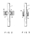
- Fig. 2 shows another embodiment of the present invention.
- a stopper or restrainer 21 for a coupling member 22 is spot-welded to the rod-form antenna element 11 at a point Q near the lower end of the antenna element 11.
- the coupling member 22 has a form of a short cylinder and is installed around the circumference of the antenna element 11 in a position which is higher than the stopper 21.
- a female screw 23 is formed on the inside circumferential surface of the coupling member 22 so that it can be screw connected to the cylinder 17 of Fig. 1.
- this embodiment has the following advantage in that even if the lower end portion of the rod-form antenna element 11 is inserted very tightly into the hole 18 (not shown in Fig. 2, see Fig. 1) so that the antenna element 11 is not easily rotated, the female screw 23 can be screwed onto the male screw 19 on the attachment base side without any difficulty by merely rotating the coupling member 22 itself.
- Fig. 3 shows a third embodiment of the present invention.
- a female screw 33 is formed by installing a helical assembly R (which is formed by coiling a wire material into a coil spring) on the inner circumferential surface of a skirt-form coupling member 32 which is fixed to the antenna element 11 at a point P by spot welding.
- a helical assembly R which is formed by coiling a wire material into a coil spring
- a coupling member which has a female screw formed on its inner circumferential surface is fastened to a lower part of a rod-form antenna element so that the coupling member is prevented from moving toward the lower end of the antenna element.
- the antenna can be screw-coupled to an attachment base mounted on the vehicle body in such a way that the lower end of the antenna element is brought into a hole formed in the attachment base and then the female screw of the coupling member is screwed to a male screw provided in the attachment base.
- the strength at the portion of the antenna element coupled to the vehicle body is great enough to ensure that there is no danger of breakage, etc., even if the load of the antenna element should be concentrated one the coupling section.
Landscapes
- Details Of Aerials (AREA)
- Support Of Aerials (AREA)
Abstract
Description
- The present invention relates to whip antennas mounted on vehicles such as automobiles, etc.
- There are various structural types of antennas used as automobile radio antennas. Among these, one type of antenna which can be manufactured at low cost while still providing sufficient radio reception (which is a minimum requirement for such antennas) is a single-length whip antenna.
- A single-length whip antenna usually includes a single, continuous rod-form conductive part which more or less matches a quarter wavelength of the FM wave band. When mounted on a vehicle, such antenna remains exposed on the outside of the vehicle body. Accordingly, high tensile materials having high recoil strength (such as high tensile strength stainless steel etc.) are used to form such an antenna so that the antenna will be able to withstand loads applied by obstructions during operation of the vehicle and/or when the vehicle is washed.
- When the whip antenna is installed on a vehicle body in the assembly line, the antenna tends to occupy a relatively large space above the vehicle body. Thus, when vehicles having such an antenna installed thereon are transported, a great deal of space is wasted in order to accommodate the antenna. For this reason, the whip antennas are usually removable from the vehicle body (that is, from an attachment base which has been mounted to the vehicle body wall) via screws, etc. so as to save maximum amount of space and facilitate the transport of more vehicles.
- Such antennas are, however, likely to suffer problems in that the material used to form the whip material must have a high tensile strength. However, such material is difficult to work with, and thus, it is difficult for example to cut threads thereon. As a result, it is also difficult to screw-couple such an antenna to the attachment base in an "as is" condition.
- In view of these problems, a structure like that shown in Fig. 4 has been employed in the prior art. Specifically, a joint 2 is attached to the base end of a whip antenna element 1, and a male screw 3 connected to this joint 2 is screwed into a
female screw 6 formed in acoupling element 5 of anattachment base 4. A material having a tensile strength lower than that of the whip antenna element 1 is used to form the joint 2 in order to secure good workability. At the same time, such material must be thoroughly sufficient in terms of strength. Accordingly, the manufacturing costs tend to be high. - In addition, there is another problem with prior art whip antennas in that even if a material of proven strength is used, the screw coupling must be in a restricted space. That is, the dimensions of the male screw portion cannot be very large. As a result, if the load (resulting from flexible bending of the whip antenna element 1) in the direction indicated by the arrow in Fig. 4 is concentrated in the screw area, the root portion of the male screw 3 may bend or break.
- Accordingly, the object of the present invention is to provide a whip antenna for use in vehicles wherein a rod-form antenna element can be screw-coupled (or removably coupled) to an attachment base and the strength of the coupling section is great enough to avoid the danger of breakage, etc., even if the load of the antenna should be concentrated at the coupling section.
- In order to accomplish this purpose, the present invention adopts the following structure:
- A coupling member having a female screw formed on its inside circumferential surface is fastened to a rod-form antenna element near the lower end thereof. The coupling member on the rod-form antenna is prevented moving downwardly (toward the vehicle body) so that it cannot move toward the lower end of the antenna element from a certain point on the antenna element. The coupling member thus mounted on the antenna element is screw-coupled to an attachment base which is mounted on a vehicle body. Screw-coupling is accomplished by inserting the lower end of the antenna element into a hole formed in the attachment base and then screwing the female screw of the coupling member to a male screw installed in the attachment base.
- With the above described structure, the base portion of the rod-form antenna element made of a highly rigid material may be used directly "as is " as a coupling core (without the necessity of a joint as conventionally required). In other words, such a base portion can be directly coupled to the attachment base. As a result, the intrinsic high rigidity and elasticity of the "whip" can be directly utilized so that the coupling strength is large and the drawbacks encountered in conventional devices is eliminated.
- This invention can be more fully understood from the following detailed description when taken in conjunction with the accompanying drawings, in which:
- Fig. 1 is a partially cross-sectional side view which illustrates the structure of the whip antenna of the present invention;
- Figs. 2 and 3 are partially cross-sectional side views which illustrate the structures of the essential parts of a second and a third embodiments of the present invention, respectively; and
- Fig. 4 illustrates a prior art antenna connection.
- In Fig. 1, a rod-
form antenna element 11 is formed from a single, high tensile strength stainless steel rod. Alternatively, this rod-form antenna element 11 may consist of a multiple number of conductive tubes of different diameters which are telescopically connected so that the tubes are free to slide relative to each other. - A skirt-
form coupling member 12 is fastened near the lower end (or base portion) of the rod-form antenna element 11. Thecoupling member 12 is fixed at a point P on theantenna element 11 by spot welding so that it does not move on the antenna element 11 (or it does not move to the lower end of the antenna element 11). Afemale screw 13 is formed on the inside circumferential surface of the skirt part of thecoupling member 12. - A
beveled area 14 consisting of hexagonally oriented surfaces are formed on the outside circumferential surface of thecoupling member 12 so that a tightening tool can be used thereon. -
Reference numeral 15 in Fig. 1 indicates an attachment base which is fastened to the vehicle body wall (not shown) beforehand. Acoupling cylinder 17 is inserted into and fastened to the inside of the central portion of thisattachment base 15 with aninner tube 16 interposed between thecoupling cylinder 17 and theattachment base 15. - The
coupling cylinder 17 has ahole 18 at the center so that the lower end of the rod-form antenna element 11 can be tightly inserted in thehole 18. Amale screw 19 which engages with thefemale screw 13 of thecoupling member 12 is formed on the outer circumferential surface of the upper end portion of thecoupling cylinder 17. - The whip antenna thus constructed is coupled to the attachment base 15 (in such a manner that the antenna can be freely installed or removed) by inserting the lower end of the rod-
form antenna element 11 into thehole 18 of thecoupling cylinder 17 secured in theattachment base 15, and then screwing thefemale screw 13 of thecoupling member 12 onto themale screw 19 of thecoupling cylinder 17 fixed to theattachment base 15. - Thus, a highly rigid and elastic material can be used for whip element and the whip antenna can be used as a coupling core "as is" so that it is able to withstand the bending stress generated by external forces. Accordingly, the coupling strength is much stronger than conventional joints, so that no bending or breakage will occur even if a large load is applied to the antenna.
- Fig. 2 shows another embodiment of the present invention. In this embodiment, a stopper or
restrainer 21 for acoupling member 22 is spot-welded to the rod-form antenna element 11 at a point Q near the lower end of theantenna element 11. Thecoupling member 22 has a form of a short cylinder and is installed around the circumference of theantenna element 11 in a position which is higher than thestopper 21. Thus, thecoupling member 22 is free to rotate but is prevented from moving toward the lower end of theantenna element 11 by thestopper 21. Afemale screw 23 is formed on the inside circumferential surface of thecoupling member 22 so that it can be screw connected to thecylinder 17 of Fig. 1. - The above structure produces the same effects and has the same merits as the embodiment of Fig. 1. In addition, this embodiment has the following advantage in that even if the lower end portion of the rod-
form antenna element 11 is inserted very tightly into the hole 18 (not shown in Fig. 2, see Fig. 1) so that theantenna element 11 is not easily rotated, thefemale screw 23 can be screwed onto themale screw 19 on the attachment base side without any difficulty by merely rotating thecoupling member 22 itself. - Fig. 3 shows a third embodiment of the present invention. In this embodiment, a
female screw 33 is formed by installing a helical assembly R (which is formed by coiling a wire material into a coil spring) on the inner circumferential surface of a skirt-form coupling member 32 which is fixed to theantenna element 11 at a point P by spot welding. - This structure produces the same effects and has the same merits as the embodiment illustrated in Fig. 1 as well as having an additional advantage in that there is no need for screw finishing (by cutting) on the inner surface of the
coupling member 32. - The present invention is not limited to the respective embodiments described above. It goes without saying that various modifications can be made without departing from the spirit of the present invention.
- As described above, according to the present invention, a coupling member which has a female screw formed on its inner circumferential surface is fastened to a lower part of a rod-form antenna element so that the coupling member is prevented from moving toward the lower end of the antenna element. Thus, the antenna can be screw-coupled to an attachment base mounted on the vehicle body in such a way that the lower end of the antenna element is brought into a hole formed in the attachment base and then the female screw of the coupling member is screwed to a male screw provided in the attachment base. Thus, in the whip antenna of the present invention, the strength at the portion of the antenna element coupled to the vehicle body is great enough to ensure that there is no danger of breakage, etc., even if the load of the antenna element should be concentrated one the coupling section.
Claims (6)
an antenna element (11) with a coupling member (12, 22, 32) provided on said antenna element, said coupling member being prevented from moving toward the lower end of said antenna at a predetermined point on said antenna and having a screw thread (13, 23, 33) on its inner surface; and
an antenna attachment base (15) provided in a vehicle body, said attachment base having a connecting cylinder (17) at its center with an inner cylinder (16) in between, and said connecting cylinder having a central hole (18) into which a lower end of said antenna element is inserted a screw thread formed on its outer surface which can connect to said screw thread of said coupling member.
Applications Claiming Priority (2)
| Application Number | Priority Date | Filing Date | Title |
|---|---|---|---|
| JP621389U JPH0298507U (en) | 1989-01-23 | 1989-01-23 | |
| JP6213/89 | 1989-01-23 |
Publications (3)
| Publication Number | Publication Date |
|---|---|
| EP0380231A2 true EP0380231A2 (en) | 1990-08-01 |
| EP0380231A3 EP0380231A3 (en) | 1991-03-27 |
| EP0380231B1 EP0380231B1 (en) | 1995-03-15 |
Family
ID=11632249
Family Applications (1)
| Application Number | Title | Priority Date | Filing Date |
|---|---|---|---|
| EP19900300465 Expired - Lifetime EP0380231B1 (en) | 1989-01-23 | 1990-01-17 | A whip antenna for use in vehicles |
Country Status (4)
| Country | Link |
|---|---|
| EP (1) | EP0380231B1 (en) |
| JP (1) | JPH0298507U (en) |
| DE (1) | DE69017727T2 (en) |
| ES (1) | ES2072382T3 (en) |
Cited By (2)
| Publication number | Priority date | Publication date | Assignee | Title |
|---|---|---|---|---|
| FR2671769A1 (en) * | 1991-01-22 | 1992-07-24 | Mat Equipement | Base body for aerial mounted on a vehicle bodywork, aerial including it and means for mounting the said aerial |
| US6014106A (en) * | 1996-11-14 | 2000-01-11 | Lk-Products Oy | Simple antenna structure |
Family Cites Families (4)
| Publication number | Priority date | Publication date | Assignee | Title |
|---|---|---|---|---|
| US2886814A (en) * | 1956-12-24 | 1959-05-12 | Charlie C Williams | Rod type antenna |
| US3138660A (en) * | 1962-11-14 | 1964-06-23 | Ward Products Corp | Automobile radio antenna |
| GB2046529B (en) * | 1978-09-27 | 1983-08-03 | Wells D H | Base loaded antenna |
| DE68926655T2 (en) * | 1988-11-22 | 1996-12-05 | Harada Ind Co Ltd | Antenna attachment with a screw coupling device |
-
1989
- 1989-01-23 JP JP621389U patent/JPH0298507U/ja active Pending
-
1990
- 1990-01-17 EP EP19900300465 patent/EP0380231B1/en not_active Expired - Lifetime
- 1990-01-17 ES ES90300465T patent/ES2072382T3/en not_active Expired - Lifetime
- 1990-01-17 DE DE1990617727 patent/DE69017727T2/en not_active Expired - Fee Related
Cited By (2)
| Publication number | Priority date | Publication date | Assignee | Title |
|---|---|---|---|---|
| FR2671769A1 (en) * | 1991-01-22 | 1992-07-24 | Mat Equipement | Base body for aerial mounted on a vehicle bodywork, aerial including it and means for mounting the said aerial |
| US6014106A (en) * | 1996-11-14 | 2000-01-11 | Lk-Products Oy | Simple antenna structure |
Also Published As
| Publication number | Publication date |
|---|---|
| EP0380231B1 (en) | 1995-03-15 |
| DE69017727T2 (en) | 1995-11-16 |
| DE69017727D1 (en) | 1995-04-20 |
| JPH0298507U (en) | 1990-08-06 |
| EP0380231A3 (en) | 1991-03-27 |
| ES2072382T3 (en) | 1995-07-16 |
Similar Documents
| Publication | Publication Date | Title |
|---|---|---|
| US5101213A (en) | Screw type coupling device and an antenna installation device using the same | |
| US5154636A (en) | Self-flaring connector for coaxial cable having a helically corrugated outer conductor | |
| EP0332853B1 (en) | Conduit joint | |
| EP0429255B1 (en) | Three-wave shared antenna (radio, AM and FM) for automobile | |
| EP0344132B1 (en) | Metal clamp for joining pipes | |
| US5325104A (en) | Whip antenna for use in vehicles | |
| EP0370715B1 (en) | An antenna installation device using a screw type coupling device | |
| US3624662A (en) | Mobile deflectable antenna with impedance matching | |
| US4300270A (en) | Housing for tightening elements of hose clips | |
| US4543548A (en) | Coaxial transmission line having an expandable and contractible bellows | |
| GB2147383A (en) | Hose fixture | |
| EP0380231A2 (en) | A whip antenna for use in vehicles | |
| US4966741A (en) | Method of making shape retention hose construction | |
| EP0757408B1 (en) | Connector for coaxial cable | |
| EP0891001A1 (en) | Anti-theft antenna | |
| US6305722B1 (en) | Telescopic tube, in particular for sprinkler systems | |
| US4376548A (en) | End fittings for conduits | |
| US4902248A (en) | Adaptors | |
| EP0104835A1 (en) | Hose pipe | |
| EP0351192B1 (en) | Automobile antenna attachment device | |
| CA1242009A (en) | Terminal case for plug connectors | |
| US3151212A (en) | Antenna fitting | |
| US6902422B1 (en) | Cable connector | |
| US5288112A (en) | Hose fitting | |
| CN215645033U (en) | Three-frequency-band common antenna |
Legal Events
| Date | Code | Title | Description |
|---|---|---|---|
| PUAI | Public reference made under article 153(3) epc to a published international application that has entered the european phase |
Free format text: ORIGINAL CODE: 0009012 |
|
| 17P | Request for examination filed |
Effective date: 19900207 |
|
| AK | Designated contracting states |
Kind code of ref document: A2 Designated state(s): DE ES FR GB IT SE |
|
| PUAL | Search report despatched |
Free format text: ORIGINAL CODE: 0009013 |
|
| AK | Designated contracting states |
Kind code of ref document: A3 Designated state(s): DE ES FR GB IT SE |
|
| 17Q | First examination report despatched |
Effective date: 19930709 |
|
| GRAA | (expected) grant |
Free format text: ORIGINAL CODE: 0009210 |
|
| AK | Designated contracting states |
Kind code of ref document: B1 Designated state(s): DE ES FR GB IT SE |
|
| ITF | It: translation for a ep patent filed | ||
| REF | Corresponds to: |
Ref document number: 69017727 Country of ref document: DE Date of ref document: 19950420 |
|
| ET | Fr: translation filed | ||
| REG | Reference to a national code |
Ref country code: ES Ref legal event code: FG2A Ref document number: 2072382 Country of ref document: ES Kind code of ref document: T3 |
|
| PLBE | No opposition filed within time limit |
Free format text: ORIGINAL CODE: 0009261 |
|
| 26N | No opposition filed | ||
| PLAA | Information modified related to event that no opposition was filed |
Free format text: ORIGINAL CODE: 0009299DELT |
|
| PLBE | No opposition filed within time limit |
Free format text: ORIGINAL CODE: 0009261 |
|
| STAA | Information on the status of an ep patent application or granted ep patent |
Free format text: STATUS: NO OPPOSITION FILED WITHIN TIME LIMIT |
|
| 26N | No opposition filed | ||
| REG | Reference to a national code |
Ref country code: GB Ref legal event code: IF02 |
|
| PGFP | Annual fee paid to national office [announced via postgrant information from national office to epo] |
Ref country code: FR Payment date: 20021227 Year of fee payment: 14 |
|
| PGFP | Annual fee paid to national office [announced via postgrant information from national office to epo] |
Ref country code: GB Payment date: 20030115 Year of fee payment: 14 |
|
| PGFP | Annual fee paid to national office [announced via postgrant information from national office to epo] |
Ref country code: SE Payment date: 20030117 Year of fee payment: 14 |
|
| PGFP | Annual fee paid to national office [announced via postgrant information from national office to epo] |
Ref country code: ES Payment date: 20030130 Year of fee payment: 14 |
|
| PGFP | Annual fee paid to national office [announced via postgrant information from national office to epo] |
Ref country code: DE Payment date: 20030227 Year of fee payment: 14 |
|
| PG25 | Lapsed in a contracting state [announced via postgrant information from national office to epo] |
Ref country code: GB Free format text: LAPSE BECAUSE OF NON-PAYMENT OF DUE FEES Effective date: 20040117 |
|
| PG25 | Lapsed in a contracting state [announced via postgrant information from national office to epo] |
Ref country code: SE Free format text: LAPSE BECAUSE OF NON-PAYMENT OF DUE FEES Effective date: 20040118 |
|
| PG25 | Lapsed in a contracting state [announced via postgrant information from national office to epo] |
Ref country code: ES Free format text: LAPSE BECAUSE OF NON-PAYMENT OF DUE FEES Effective date: 20040119 |
|
| PG25 | Lapsed in a contracting state [announced via postgrant information from national office to epo] |
Ref country code: DE Free format text: LAPSE BECAUSE OF NON-PAYMENT OF DUE FEES Effective date: 20040803 |
|
| EUG | Se: european patent has lapsed | ||
| GBPC | Gb: european patent ceased through non-payment of renewal fee |
Effective date: 20040117 |
|
| PG25 | Lapsed in a contracting state [announced via postgrant information from national office to epo] |
Ref country code: FR Free format text: LAPSE BECAUSE OF NON-PAYMENT OF DUE FEES Effective date: 20040930 |
|
| REG | Reference to a national code |
Ref country code: FR Ref legal event code: ST |
|
| PG25 | Lapsed in a contracting state [announced via postgrant information from national office to epo] |
Ref country code: IT Free format text: LAPSE BECAUSE OF NON-PAYMENT OF DUE FEES;WARNING: LAPSES OF ITALIAN PATENTS WITH EFFECTIVE DATE BEFORE 2007 MAY HAVE OCCURRED AT ANY TIME BEFORE 2007. THE CORRECT EFFECTIVE DATE MAY BE DIFFERENT FROM THE ONE RECORDED. Effective date: 20050117 |
|
| REG | Reference to a national code |
Ref country code: ES Ref legal event code: FD2A Effective date: 20040119 |