EP0380287A2 - Griffe für Schirme - Google Patents
Griffe für Schirme Download PDFInfo
- Publication number
- EP0380287A2 EP0380287A2 EP90300671A EP90300671A EP0380287A2 EP 0380287 A2 EP0380287 A2 EP 0380287A2 EP 90300671 A EP90300671 A EP 90300671A EP 90300671 A EP90300671 A EP 90300671A EP 0380287 A2 EP0380287 A2 EP 0380287A2
- Authority
- EP
- European Patent Office
- Prior art keywords
- tip
- cup
- sleeve
- handle
- shaft
- Prior art date
- Legal status (The legal status is an assumption and is not a legal conclusion. Google has not performed a legal analysis and makes no representation as to the accuracy of the status listed.)
- Granted
Links
- 210000002105 tongue Anatomy 0.000 claims description 6
- 239000004033 plastic Substances 0.000 claims description 5
- 229920003023 plastic Polymers 0.000 claims description 5
- 239000000463 material Substances 0.000 claims description 3
- 230000014759 maintenance of location Effects 0.000 claims description 2
- 238000004519 manufacturing process Methods 0.000 abstract description 3
- 238000010276 construction Methods 0.000 abstract description 2
- 238000003754 machining Methods 0.000 description 2
- 239000002184 metal Substances 0.000 description 2
- 238000000465 moulding Methods 0.000 description 2
- 230000000712 assembly Effects 0.000 description 1
- 238000000429 assembly Methods 0.000 description 1
- 238000005520 cutting process Methods 0.000 description 1
- 230000000717 retained effect Effects 0.000 description 1
- 238000003892 spreading Methods 0.000 description 1
- 239000002023 wood Substances 0.000 description 1
Images

Classifications
-
- A—HUMAN NECESSITIES
- A45—HAND OR TRAVELLING ARTICLES
- A45B—WALKING STICKS; UMBRELLAS; LADIES' OR LIKE FANS
- A45B25/00—Details of umbrellas
- A45B25/12—Devices for holding umbrellas closed, e.g. magnetic devices
-
- A—HUMAN NECESSITIES
- A45—HAND OR TRAVELLING ARTICLES
- A45B—WALKING STICKS; UMBRELLAS; LADIES' OR LIKE FANS
- A45B25/00—Details of umbrellas
- A45B25/02—Umbrella frames
-
- A—HUMAN NECESSITIES
- A45—HAND OR TRAVELLING ARTICLES
- A45B—WALKING STICKS; UMBRELLAS; LADIES' OR LIKE FANS
- A45B9/00—Details
- A45B9/02—Handles or heads
-
- Y—GENERAL TAGGING OF NEW TECHNOLOGICAL DEVELOPMENTS; GENERAL TAGGING OF CROSS-SECTIONAL TECHNOLOGIES SPANNING OVER SEVERAL SECTIONS OF THE IPC; TECHNICAL SUBJECTS COVERED BY FORMER USPC CROSS-REFERENCE ART COLLECTIONS [XRACs] AND DIGESTS
- Y10—TECHNICAL SUBJECTS COVERED BY FORMER USPC
- Y10S—TECHNICAL SUBJECTS COVERED BY FORMER USPC CROSS-REFERENCE ART COLLECTIONS [XRACs] AND DIGESTS
- Y10S16/00—Miscellaneous hardware, e.g. bushing, carpet fastener, caster, door closer, panel hanger, attachable or adjunct handle, hinge, window sash balance
- Y10S16/19—Cast or molded handles
-
- Y—GENERAL TAGGING OF NEW TECHNOLOGICAL DEVELOPMENTS; GENERAL TAGGING OF CROSS-SECTIONAL TECHNOLOGIES SPANNING OVER SEVERAL SECTIONS OF THE IPC; TECHNICAL SUBJECTS COVERED BY FORMER USPC CROSS-REFERENCE ART COLLECTIONS [XRACs] AND DIGESTS
- Y10—TECHNICAL SUBJECTS COVERED BY FORMER USPC
- Y10S—TECHNICAL SUBJECTS COVERED BY FORMER USPC CROSS-REFERENCE ART COLLECTIONS [XRACs] AND DIGESTS
- Y10S16/00—Miscellaneous hardware, e.g. bushing, carpet fastener, caster, door closer, panel hanger, attachable or adjunct handle, hinge, window sash balance
- Y10S16/24—Handle fastening means
Definitions
- the invention relates to handles and handle assemblies for umbrella frames.
- Umbrellas of the kind having a handle, a shaft and several ribs and stretchers supporting the cover, in which the ribs fold down on to the shaft when the umbrella is not in use usually also have a "tip-cup", i.e. an annular recessed retainer slidably mounted on the shaft next to the handle to hold the (usually beaded) tips of the ribs close to the shaft.
- the tip-cup can be slid axially up the shaft when it is desired to retain the tips of the ribs in the folded-down condition and down towards the handle to free the rib ends for unfolding or erecting the umbrella.
- Another prior art construction uses an additional metal sleeve part, fixed to the shaft adjacent the handle, for the tip-cup to slide on. This ensures a correct clearance and good sliding behaviour for the tip-cup; a flange on the sleeve at the end away from the handle ensures that the cup remains on the sleeve.
- an additional part is undesirable from a manufacturing point of view.
- an umbrella handle into which a shaft can be inserted, characterised in that it has a sleeve-shaped integral axial extension on the shaft side for receiving a tip-cup to be slidably mounted thereon, the sleeve having an abutment over which a tip-cup can be passed before assembly of the handle to an umbrella shaft, to prevent the tip-cup sliding off the extension after assembly.
- the abutment may be afforded by an outwardly protruding portion, for example an annular or part-annular lip integral with the end of the sleeve extension.
- the sleeve may be slit in the longitudinal direction so as to form two or more tongues, the free ends of which can be radially compressed slightly to allow the tip-cup to be slid on to it before the shaft is inserted into the handle when the tongues will be kept apart by the shaft thereby ensuring that the tip-cup is held captive on the sleeve.
- the sleeve may further have an integral pip or collar at an intermediate point along its length so as to provide additional retention for the tip-cup in its forward position (i.e. when holding the umbrella tips closed).
- the handle according to the invention may conveniently be moulded in one piece integrally with the smaller diameter sleeve extension from moldable plastics, though in other embodiments the extension could be made by machining.
- the invention also comprises a handle as defined, with a tip-cup for it; and such a handle assembly when mounted on an umbrella shaft as part of an umbrella frame.
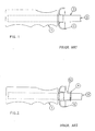
- Figure 1 shows a known handle assembly consisting of a handle 1 into which a shaft 9 is inserted, the shaft being deformed at a location 3 a short distance from the upper end of the handle.
- a tip-cup 6 slides axially on the shaft between the end of the handle and the deformation 3; the tip cup 6 naturally has to be fitted on the shaft before the latter is inserted in the handle.
- the cup 6 is prone to being too loose for effective operation or too tight for convenience of use, depending on the actual diameter of the shaft, particularly if the latter is painted with a layer of a thickness which is variable or difficult to control.
- Figure 2 shows another known arrangement where an additional sleeve 10 is provided, secured to the shaft 9 at the end of the handle 1.
- the sleeve 10 has a flange or lip 4 at the end away from the handle so as to retain the tip-cup 6 after assembly.
- the provision of an additional part complicates the manufacturing process, though the frictional sliding engagement of the tip-cup on the sleeve 10 can be controlled better.
- FIG. 3 shows a handle in accordance with the invention.
- the main part of the handle is made of plastics material and has a conventional shape but its upper end (i.e. the end towards the head of the umbrella) has an integral sleeve 2 through which the shaft can pass.
- the sleeve terminates in a slight lip 4 forming an abutment for retaining a tip-cup, and it is axially slit to form slots 5 so that the free ends of the sections or tongues can be slightly compressed radially during assembly in order to allow the tip-cup to pass over the lip portions 4 onto the sleeve before inserting the shaft into the handle through the sleeve.
- the abutment lip 4 cannot again be compressed owing to the presence of the shaft inside the sleeve 2, and the abutment lip 4 thus prevents the tip-cup sliding off the sleeve and up the shaft.
- Figure 3A shows an end view of the sleeve and handle.
- there are four axial slots 5 which provide four arcuate tongues, though it will be appreciated that there could alternatively be only two or three slots and tongues, or more than four.
- Conceivably a sleeve with merely one slot could be used if it could be closed sufficiently to reduce the lip diameter to allow the hole in the tip-cup to fit over it.
- the tip-cup 6 when the tip-cup 6 is mounted on the sleeve the tip-cup can slide on the sleeve a short distance defined between a lower position adjacent the handle proper and the upper position defined by the lip 4. Since the sleeve is moulded integrally with the handle, the tolerance required for sliding can be easily maintained.
- the sleeve has a small protrusion or pip 3 which normally confines the tip-cup 6 to one or other part of the sleeve because the tip-cup can only pass over the pip 3 using slight pressure and it will not slide over the pip freely inadvertently.
- a significant advantage of a handle in accordance with the invention is that it can be moulded in one piece from any suitable mouldable plastics material with the sleeve for the tip-cup formed integrally during moulding.
- a handle according to the invention it would be possible to make a handle according to the invention other han by moulding, e.g. by machining from wood, metal or plastics, and in that respect the invention is applicable to any type or shape of umbrella handle.
- the sleeve would simply be machined by turning it down to a smaller diameter, leaving the end lip, and then cutting the axial slots.
- the axial slots need not extend the full axial extent of the sleeve provided they are long enough to allow the lipped end to be compressed.
- the sleeve need not necessarily be radially compressible by means of such slots; other means could be provided for allowing the tip-cup to be slid onto the sleeve and keep it from sliding off, e.g. by resilience of the sleeve or tip-cup itself.
- the abutment is constituted by a lip as shown, it need not be present all round the sleeve end in the form of an annulus; one or more part-annular portions would do. In other embodiments, the abutment could be at minimum just one protrusion, or two diametrically opposite protrusions, could suffice.
Landscapes
- Walking Sticks, Umbrellas, And Fans (AREA)
Applications Claiming Priority (2)
| Application Number | Priority Date | Filing Date | Title |
|---|---|---|---|
| GB8901472 | 1989-01-24 | ||
| GB898901472A GB8901472D0 (en) | 1989-01-24 | 1989-01-24 | Umbrella handle |
Publications (3)
| Publication Number | Publication Date |
|---|---|
| EP0380287A2 true EP0380287A2 (de) | 1990-08-01 |
| EP0380287A3 EP0380287A3 (de) | 1991-04-24 |
| EP0380287B1 EP0380287B1 (de) | 1994-07-20 |
Family
ID=10650481
Family Applications (1)
| Application Number | Title | Priority Date | Filing Date |
|---|---|---|---|
| EP90300671A Expired - Lifetime EP0380287B1 (de) | 1989-01-24 | 1990-01-23 | Griffe für Schirme |
Country Status (4)
| Country | Link |
|---|---|
| US (1) | US5048152A (de) |
| EP (1) | EP0380287B1 (de) |
| DE (1) | DE69010702T2 (de) |
| GB (1) | GB8901472D0 (de) |
Cited By (1)
| Publication number | Priority date | Publication date | Assignee | Title |
|---|---|---|---|---|
| CN104998398A (zh) * | 2015-06-19 | 2015-10-28 | 中山市迈进高尔夫用品有限公司 | 一种高尔夫球杆防脱手夹套 |
Families Citing this family (3)
| Publication number | Priority date | Publication date | Assignee | Title |
|---|---|---|---|---|
| US5349976A (en) * | 1993-10-01 | 1994-09-27 | Ko Fu Y | Structure of umbrella ring |
| US7252103B2 (en) * | 2005-03-21 | 2007-08-07 | Ching-Chuan You | Opening device of automatic umbrella |
| US11618529B2 (en) | 2020-06-03 | 2023-04-04 | Dextera Brakes, Llc | Grip assembly for vehicle |
Citations (1)
| Publication number | Priority date | Publication date | Assignee | Title |
|---|---|---|---|---|
| US3882880A (en) | 1974-06-14 | 1975-05-13 | Haas Jordan Company | Umbrella tip cup |
Family Cites Families (5)
| Publication number | Priority date | Publication date | Assignee | Title |
|---|---|---|---|---|
| US1042417A (en) * | 1911-03-25 | 1912-10-29 | Walter M Jackson | Adjustable rib-tip-holding umbrella-handle. |
| DE255595C (de) * | 1912-01-03 | |||
| GB345412A (en) * | 1930-02-03 | 1931-03-26 | David Stott Cooper | Improvements in umbrellas |
| GB619692A (en) * | 1946-07-10 | 1949-03-14 | John Jacob Singer | Improvements in retaining devices for the ribs of umbrellas and the like |
| FR1259432A (fr) * | 1960-03-14 | 1961-04-28 | Perfectionnements aux dispositifs de retenue des baleines de parapluies, ombrelles et analogues |
-
1989
- 1989-01-24 GB GB898901472A patent/GB8901472D0/en active Pending
-
1990
- 1990-01-22 US US07/468,001 patent/US5048152A/en not_active Expired - Fee Related
- 1990-01-23 DE DE69010702T patent/DE69010702T2/de not_active Expired - Lifetime
- 1990-01-23 EP EP90300671A patent/EP0380287B1/de not_active Expired - Lifetime
Patent Citations (1)
| Publication number | Priority date | Publication date | Assignee | Title |
|---|---|---|---|---|
| US3882880A (en) | 1974-06-14 | 1975-05-13 | Haas Jordan Company | Umbrella tip cup |
Cited By (1)
| Publication number | Priority date | Publication date | Assignee | Title |
|---|---|---|---|---|
| CN104998398A (zh) * | 2015-06-19 | 2015-10-28 | 中山市迈进高尔夫用品有限公司 | 一种高尔夫球杆防脱手夹套 |
Also Published As
| Publication number | Publication date |
|---|---|
| DE69010702D1 (de) | 1994-08-25 |
| EP0380287A3 (de) | 1991-04-24 |
| DE69010702T2 (de) | 1994-10-27 |
| EP0380287B1 (de) | 1994-07-20 |
| US5048152A (en) | 1991-09-17 |
| GB8901472D0 (en) | 1989-03-15 |
Similar Documents
| Publication | Publication Date | Title |
|---|---|---|
| EP1186788B1 (de) | Clip | |
| US5504962A (en) | Holder for cosmetic or hygienic item | |
| EP0291589B1 (de) | Selbstöffnender und selbstschliessender automatischer Schirm mit einer einzigen Drucktaste | |
| EP0212530A1 (de) | Scheidwerkzeug | |
| US20050081902A1 (en) | Umbrella actuator | |
| KR101639354B1 (ko) | 재료도포장치를 포함한 키트 및 그 키트의 사용 | |
| EP0156045A1 (de) | Völlig automatischer Schirm mit einem einzigen Druckknopf | |
| JP2004512889A (ja) | 家庭電気器具用伸縮式延長具 | |
| US3799180A (en) | Umbrella handle | |
| EP0380287B1 (de) | Griffe für Schirme | |
| JP3971302B2 (ja) | ペン | |
| JP2756762B2 (ja) | パイプ連結構造 | |
| DK152701B (da) | Udloesemekanisme for en glider i en sammenklappelig skaerm, saasom en paraply eller parasol | |
| US5004364A (en) | Device for advancing and retracting writing element in writing instrument | |
| US11882915B2 (en) | Refillable container | |
| EP0524600A1 (de) | Behälter zum Entfalten von stiftförmigen Produkten | |
| US6964434B2 (en) | Coupling part by which at least one tubular or bar-shaped part is connected to a further part | |
| JPH11513923A (ja) | 軟芯ペンシル | |
| EP0538503B1 (de) | Kugelschreiber mit einem drehbaren Nocken | |
| CN213820222U (zh) | 可替换中套的包装管 | |
| US5027514A (en) | Scissors and grip | |
| JP2604657Y2 (ja) | 棒状部材の繰り出し装置 | |
| JPS6021534Y2 (ja) | 伸縮管 | |
| GB2290264A (en) | Projecting and retracting mechanism for writing instruments. | |
| EP0291866A1 (de) | Mechanischer Druckbleistift |
Legal Events
| Date | Code | Title | Description |
|---|---|---|---|
| PUAI | Public reference made under article 153(3) epc to a published international application that has entered the european phase |
Free format text: ORIGINAL CODE: 0009012 |
|
| AK | Designated contracting states |
Kind code of ref document: A2 Designated state(s): DE FR GB IT |
|
| PUAL | Search report despatched |
Free format text: ORIGINAL CODE: 0009013 |
|
| AK | Designated contracting states |
Kind code of ref document: A3 Designated state(s): DE FR GB IT |
|
| 17P | Request for examination filed |
Effective date: 19910816 |
|
| 17Q | First examination report despatched |
Effective date: 19921229 |
|
| GRAA | (expected) grant |
Free format text: ORIGINAL CODE: 0009210 |
|
| AK | Designated contracting states |
Kind code of ref document: B1 Designated state(s): DE FR GB IT |
|
| ITF | It: translation for a ep patent filed | ||
| REF | Corresponds to: |
Ref document number: 69010702 Country of ref document: DE Date of ref document: 19940825 |
|
| ET | Fr: translation filed | ||
| PLBE | No opposition filed within time limit |
Free format text: ORIGINAL CODE: 0009261 |
|
| STAA | Information on the status of an ep patent application or granted ep patent |
Free format text: STATUS: NO OPPOSITION FILED WITHIN TIME LIMIT |
|
| 26N | No opposition filed | ||
| REG | Reference to a national code |
Ref country code: GB Ref legal event code: IF02 |
|
| PGFP | Annual fee paid to national office [announced via postgrant information from national office to epo] |
Ref country code: DE Payment date: 20090115 Year of fee payment: 20 |
|
| PGFP | Annual fee paid to national office [announced via postgrant information from national office to epo] |
Ref country code: GB Payment date: 20090121 Year of fee payment: 20 |
|
| PGFP | Annual fee paid to national office [announced via postgrant information from national office to epo] |
Ref country code: IT Payment date: 20090127 Year of fee payment: 20 |
|
| PGFP | Annual fee paid to national office [announced via postgrant information from national office to epo] |
Ref country code: FR Payment date: 20090113 Year of fee payment: 20 |
|
| REG | Reference to a national code |
Ref country code: GB Ref legal event code: PE20 Expiry date: 20100122 |
|
| PG25 | Lapsed in a contracting state [announced via postgrant information from national office to epo] |
Ref country code: GB Free format text: LAPSE BECAUSE OF EXPIRATION OF PROTECTION Effective date: 20100122 |
|
| PG25 | Lapsed in a contracting state [announced via postgrant information from national office to epo] |
Ref country code: DE Free format text: LAPSE BECAUSE OF EXPIRATION OF PROTECTION Effective date: 20100123 |