EP0380461A1 - Ladevorrichtung für Feuerwaffen - Google Patents
Ladevorrichtung für Feuerwaffen Download PDFInfo
- Publication number
- EP0380461A1 EP0380461A1 EP90870003A EP90870003A EP0380461A1 EP 0380461 A1 EP0380461 A1 EP 0380461A1 EP 90870003 A EP90870003 A EP 90870003A EP 90870003 A EP90870003 A EP 90870003A EP 0380461 A1 EP0380461 A1 EP 0380461A1
- Authority
- EP
- European Patent Office
- Prior art keywords
- loading mechanism
- mechanism according
- spring
- piston
- improved weapon
- Prior art date
- Legal status (The legal status is an assumption and is not a legal conclusion. Google has not performed a legal analysis and makes no representation as to the accuracy of the status listed.)
- Withdrawn
Links
- 230000007246 mechanism Effects 0.000 title claims abstract description 38
- 230000006835 compression Effects 0.000 claims abstract description 4
- 238000007906 compression Methods 0.000 claims abstract description 4
- 230000009467 reduction Effects 0.000 claims description 7
- 239000013013 elastic material Substances 0.000 claims 1
- 239000003638 chemical reducing agent Substances 0.000 abstract 1
- 230000009471 action Effects 0.000 description 8
- 239000000463 material Substances 0.000 description 2
- 229910000639 Spring steel Inorganic materials 0.000 description 1
- 240000008042 Zea mays Species 0.000 description 1
- 230000008901 benefit Effects 0.000 description 1
- 230000005540 biological transmission Effects 0.000 description 1
- 230000008859 change Effects 0.000 description 1
- 238000010276 construction Methods 0.000 description 1
- 238000006073 displacement reaction Methods 0.000 description 1
Images

Classifications
-
- F—MECHANICAL ENGINEERING; LIGHTING; HEATING; WEAPONS; BLASTING
- F41—WEAPONS
- F41B—WEAPONS FOR PROJECTING MISSILES WITHOUT USE OF EXPLOSIVE OR COMBUSTIBLE PROPELLANT CHARGE; WEAPONS NOT OTHERWISE PROVIDED FOR
- F41B11/00—Compressed-gas guns, e.g. air guns; Steam guns
- F41B11/50—Magazines for compressed-gas guns; Arrangements for feeding or loading projectiles from magazines
- F41B11/57—Electronic or electric systems for feeding or loading
-
- F—MECHANICAL ENGINEERING; LIGHTING; HEATING; WEAPONS; BLASTING
- F41—WEAPONS
- F41A—FUNCTIONAL FEATURES OR DETAILS COMMON TO BOTH SMALLARMS AND ORDNANCE, e.g. CANNONS; MOUNTINGS FOR SMALLARMS OR ORDNANCE
- F41A7/00—Auxiliary mechanisms for bringing the breech-block or bolt or the barrel to the starting position before automatic firing; Drives for externally-powered guns; Remote-controlled gun chargers
- F41A7/02—Machine gun rechargers, e.g. manually operated
- F41A7/06—Machine gun rechargers, e.g. manually operated electrically operated
-
- F—MECHANICAL ENGINEERING; LIGHTING; HEATING; WEAPONS; BLASTING
- F41—WEAPONS
- F41B—WEAPONS FOR PROJECTING MISSILES WITHOUT USE OF EXPLOSIVE OR COMBUSTIBLE PROPELLANT CHARGE; WEAPONS NOT OTHERWISE PROVIDED FOR
- F41B11/00—Compressed-gas guns, e.g. air guns; Steam guns
- F41B11/60—Compressed-gas guns, e.g. air guns; Steam guns characterised by the supply of compressed gas
- F41B11/64—Compressed-gas guns, e.g. air guns; Steam guns characterised by the supply of compressed gas having a piston effecting a compressor stroke during the firing of each shot
- F41B11/642—Compressed-gas guns, e.g. air guns; Steam guns characterised by the supply of compressed gas having a piston effecting a compressor stroke during the firing of each shot the piston being spring operated
- F41B11/646—Arrangements for putting the spring under tension
Definitions
- This invention relates to an improved automatic weapon loading mechanism, more particularly of the type of which a spring must be tensioned for the discharge of a blow.
- this mechanism will be used on air rifles.
- This mechanism has the disadvantage that the nut will have to continually make a back and forth movement, in order to return to its initial position after the load of the blow where the repositioning of the nut is an action which takes energy and time.
- the present invention relates to a loading mechanism for weapons in which a double-turn loading system is applied which, if necessary after loading, can immediately perform a new loading action without having to perform a prior return action.
- Such an improved weapon loading mechanism consists mainly of a piston actuated by a spring and an electric motor with reduction gear, characterized in that the spring is compressed by the piston where the recoil displacement which results in tension of the above spring is controlled by the cooperation of the piston with an endless traction device.
- the traction device in a preferred embodiment consists of a circulating chain, controlled and supported by chain wheels.
- This chain is preferably provided with two protruding shafts, at two opposite locations which, alternately, continuously resume the same start and stop positions in order to perform a loading operation or not.
- An additional advantage of the present invention also consists in that a hook-shaped element which can be pulled by a shaft which is preferably provided on an endless chain is connected to the piston, in such a way that when the said spring is located practically at the end of its tension stroke, (i.e. in its compressed position) the above-mentioned shaft is positioned exactly where it will make a circular circuit. Therefore, it follows that this tree, during the first 90 degrees of the circular path performed, will have a horizontal velocity component from the initial (0 degrees) to zero (90 degrees). This speed component can be calculated for each positioning by multiplying the initial horizontal speed component with the sine of the angle in which the tree is located. It is clear that the horizontal velocity component will have a sinusoidal progression.
- Figure 1 shows a weapon 1, in this case an air rifle, in which the improved mechanism is indicated by part F2 and in which the energy for this charging mechanism is, for example, supplied by a battery 2 installed in the butt.
- the motor 4 and the reduction gear 5 are shown diagrammatically, mounted in the housing 3.
- the motor 4 produces a rotary movement transmitted to the reduction gear 5 by means of a shaft 6.
- the reduction gear transmits the rotary movement through the shaft 7 provided with a bevel gear 8 which can cooperate with a second bevel gear 9 on which an accessory chain wheel 10 is provided.
- the latter is connected to a similar chain wheel 11 via a chain 12, on which two protruding shafts 13-14 are provided in this case.
- the toothed and chain wheels 9, 10 and 11 are mounted on bearing shafts which can rotate freely in the housing 3.
- a piston 15 with control spring 16 provided which are installed in a chamber 17 around a rod.
- a flexible forked element 18, for example made of spring steel, bent downwards and which has a fold like a hook 19 at its free end is suitably provided for the piston 15.
- the element 18 extends, through a slot 20, into the chamber 21 where the control mechanism is located.
- the toothed wheel 9 and the chain wheel 10 is located on a shaft 22 while the chain wheel 11 is located on the shaft 23.
- the parts of the shaft 23 next to the chain 12, i.e. d. the parts of the shaft 23 which may be at a given moment under the arms of the element 18, are only constituted by a segment 24 whose scope will be explained below.
- the operation of the loading mechanism according to the invention is very simple and as follows.
- the loading mechanism In the rest position, the loading mechanism is in the position as shown in FIG. 2.
- the motor 4 By controlling an electric switch not shown in the drawings, the motor 4 can be supplied with current.
- the engine turns the chain wheel 10 will drive the chain, thanks to suitable transmission means 6 to 9, along arrow P.
- the protruding shafts 13 will engage at a determined moment in the hook-shaped fold 19 of the element 18 and, consequently, training the latter.
- the piston 15, to which the element 18 is fixed will also be driven and will compress the spring 16.
- the shafts 13 will then continue to perform a rectilinear horizontal movement up to the chain wheel 11 and more particularly up to the position A. From point A, the shaft 13 will deviate from its initial rectilinear horizontal movement and start a circular movement from position A to position C. In this way the original horizontal movement component in position A, between positions A and C, will be partially converted into a vertical movement.
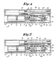
- the chain 12 will drive the shafts 13 to a position, as shown in Figure 4, after which the hook 19 is released from the shafts 13 so that the element 18 returns to a position as shown in the figure 5, since the segments 24, more particularly their edges 25 also act on this element 18 in order to ensure its clearance with respect to the shafts 13 in this case. From this moment the motor 4 will stop turning.
- This can be applied by installing a limit switch not shown in the drawings at a suitable location and requested either by the chain 12 or by the element 18.
- the piston 15 can then be unlocked, for example, by an expansion mechanism, also not shown, which can be controlled from the trigger 22.
- the shafts 13 are placed in the position of the shafts 14 in FIG. 2 and the shafts 14 have taken the starting position of the shafts 13 in order to be ready for a new loading. .
- FIG 5 shows the loading position which, after an unloading command, will change to take the position as shown in Figure 2, with the difference that now, the shafts 13 and 14 have changed places.
- a system which is especially applicable for air rifles is the embodiment described above. It is obvious that this improved loading mechanism can also be used on other kinds of weapons and for other purposes.
Landscapes
- Engineering & Computer Science (AREA)
- General Engineering & Computer Science (AREA)
- Devices For Conveying Motion By Means Of Endless Flexible Members (AREA)
- Springs (AREA)
- Gear Transmission (AREA)
- Output Control And Ontrol Of Special Type Engine (AREA)
Applications Claiming Priority (2)
| Application Number | Priority Date | Filing Date | Title |
|---|---|---|---|
| BE8900058 | 1989-01-19 | ||
| BE8900058A BE1002750A3 (fr) | 1989-01-19 | 1989-01-19 | Mecanisme de chargement d'armes ameliore. |
Publications (1)
| Publication Number | Publication Date |
|---|---|
| EP0380461A1 true EP0380461A1 (de) | 1990-08-01 |
Family
ID=3883965
Family Applications (1)
| Application Number | Title | Priority Date | Filing Date |
|---|---|---|---|
| EP90870003A Withdrawn EP0380461A1 (de) | 1989-01-19 | 1990-01-04 | Ladevorrichtung für Feuerwaffen |
Country Status (6)
| Country | Link |
|---|---|
| US (1) | US5129383A (de) |
| EP (1) | EP0380461A1 (de) |
| BE (1) | BE1002750A3 (de) |
| BR (1) | BR9000208A (de) |
| DE (1) | DE380461T1 (de) |
| ES (1) | ES2018775A4 (de) |
Cited By (1)
| Publication number | Priority date | Publication date | Assignee | Title |
|---|---|---|---|---|
| FR2681674A1 (fr) * | 1991-09-25 | 1993-03-26 | Dorval Pierre | Dispositif de rearmement et arme a air comprime ainsi equipee. |
Families Citing this family (10)
| Publication number | Priority date | Publication date | Assignee | Title |
|---|---|---|---|---|
| CA2287033A1 (en) | 1999-10-21 | 2001-04-21 | Geoid Exploration Ltd. | Land-marking device and a method of land surveying and marking |
| US6857422B2 (en) * | 2003-06-12 | 2005-02-22 | Tricord Solutions, Inc. | Portable electric driven compressed air gun |
| US8505798B2 (en) * | 2005-05-12 | 2013-08-13 | Stanley Fastening Systems, L.P. | Fastener driving device |
| US20080017689A1 (en) * | 2006-05-31 | 2008-01-24 | David Simonelli | Fastener driving device |
| WO2006124498A2 (en) * | 2005-05-12 | 2006-11-23 | Stanley Fastening Systems, L.P. | Fastener driving device |
| USD587766S1 (en) | 2006-07-20 | 2009-03-03 | Kee Action Sports I Llc | Paintball field marker |
| US20100116864A1 (en) * | 2008-11-07 | 2010-05-13 | Pneutools, Incorporated | Motorized fastener applicator |
| KR101716178B1 (ko) * | 2011-02-08 | 2017-03-14 | 한화테크윈 주식회사 | 자동 장전 장치 및 화기 조립체 |
| US10955215B2 (en) | 2019-08-22 | 2021-03-23 | Tricord Solutions, Inc. | Projectile launching apparatus |
| US12569969B2 (en) * | 2023-06-08 | 2026-03-10 | Tricord Solutions, Inc. | Impacting apparatus |
Citations (3)
| Publication number | Priority date | Publication date | Assignee | Title |
|---|---|---|---|---|
| US2180751A (en) * | 1938-01-11 | 1939-11-21 | Paul G Wagner | Machine gun starter and recharger |
| US3198075A (en) * | 1961-06-02 | 1965-08-03 | Brevets Aero Mecaniques | Automatic firearm with a recoiling barrel |
| BE905904A (fr) * | 1986-12-12 | 1987-04-01 | Ct D Innovations Et De Rech S | Arme a air comprime. |
Family Cites Families (6)
| Publication number | Priority date | Publication date | Assignee | Title |
|---|---|---|---|---|
| US1869600A (en) * | 1927-10-08 | 1932-08-02 | Remington Arms Co Inc | Air-gun |
| US2814041A (en) * | 1955-03-14 | 1957-11-26 | Emmett L Haley | Power devices |
| US2834332A (en) * | 1955-07-18 | 1958-05-13 | John M Guthrie | Toy gun |
| DE2313631A1 (de) * | 1973-03-19 | 1974-10-10 | Richard Hehn | Verdichtungsmechanismus fuer druckluftwaffen |
| GB1445529A (en) * | 1973-04-26 | 1976-08-11 | Daishin Kogyo Kk | Toy gun process and apparatus |
| GB2181524B (en) * | 1985-10-14 | 1989-02-08 | Roy Hutchison | Spring piston air weapon |
-
1989
- 1989-01-19 BE BE8900058A patent/BE1002750A3/fr not_active IP Right Cessation
-
1990
- 1990-01-04 ES ES90870003T patent/ES2018775A4/es active Pending
- 1990-01-04 EP EP90870003A patent/EP0380461A1/de not_active Withdrawn
- 1990-01-04 DE DE199090870003T patent/DE380461T1/de active Pending
- 1990-01-18 US US07/466,933 patent/US5129383A/en not_active Expired - Fee Related
- 1990-01-19 BR BR909000208A patent/BR9000208A/pt unknown
Patent Citations (3)
| Publication number | Priority date | Publication date | Assignee | Title |
|---|---|---|---|---|
| US2180751A (en) * | 1938-01-11 | 1939-11-21 | Paul G Wagner | Machine gun starter and recharger |
| US3198075A (en) * | 1961-06-02 | 1965-08-03 | Brevets Aero Mecaniques | Automatic firearm with a recoiling barrel |
| BE905904A (fr) * | 1986-12-12 | 1987-04-01 | Ct D Innovations Et De Rech S | Arme a air comprime. |
Cited By (2)
| Publication number | Priority date | Publication date | Assignee | Title |
|---|---|---|---|---|
| FR2681674A1 (fr) * | 1991-09-25 | 1993-03-26 | Dorval Pierre | Dispositif de rearmement et arme a air comprime ainsi equipee. |
| WO1993006428A1 (fr) * | 1991-09-25 | 1993-04-01 | Pierre Dorval | Dispositif de rearmement et arme a air comprime ainsi equipee |
Also Published As
| Publication number | Publication date |
|---|---|
| BR9000208A (pt) | 1990-11-13 |
| US5129383A (en) | 1992-07-14 |
| DE380461T1 (de) | 1991-04-11 |
| ES2018775A4 (es) | 1991-05-16 |
| BE1002750A3 (fr) | 1991-05-28 |
Similar Documents
| Publication | Publication Date | Title |
|---|---|---|
| EP0380461A1 (de) | Ladevorrichtung für Feuerwaffen | |
| EP2501914B1 (de) | Vorrichtung zum ändern des übersetzungsverhältnisses zwischen einer turbinenwelle und einer anlasser-/generatorwelle eines flugzeugmotors | |
| FR2772734A1 (fr) | Dispositif de transfert et convoyeur equipe d'un tel dispositif | |
| FR2657061A1 (fr) | Dispositif de transmission a engrenages pour bicyclette. | |
| EP0694750A1 (de) | Munitionszufuhrsystem für Waffen von kleinem oder mittlerem Kaliber | |
| FR2651044A1 (fr) | Appareil photographique motorise | |
| EP4031828B1 (de) | Zielabschussvorrichtung | |
| FR2698053A1 (fr) | Servo-entraînement de positionnement en particulier pour un embrayage à friction d'un véhicule automobile ou une boîte de vitesses d'un véhicule automobile. | |
| FR2546454A1 (fr) | Vehicule de travail autopropulse | |
| EP0200584B1 (de) | Fremdangetriebene automatische Waffe | |
| FR2613777A1 (fr) | Demarreur pour moteur de vehicule | |
| KR19980702392A (ko) | 기계식 시동 모터 | |
| CH639732A5 (fr) | Mecanisme d'embrayage. | |
| EP0050891A1 (de) | Windmotor | |
| FR2486610A1 (fr) | Dispositif d'entrainement rotatif a deux vitesses, notamment pour alternateur de vehicule automobile | |
| FR2727376A1 (fr) | Derailleur electronique | |
| EP0571285A1 (de) | Automatische Waffe mit einer kippbaren Patronenkammer zum Abschiessen von teleskopischen zylindrischen Munitionen | |
| WO2013135990A1 (fr) | Commande de crabot d'une boite de vitesses, comportant un basculeur | |
| EP0012046B1 (de) | Elektrischer Anlasser für Brennkraftmaschinen, insbesondere für Kraftfahrzeuge | |
| FR2805020A1 (fr) | Boite de vitesses a freinage selectif d'arbre moteur et procede de mise en oeuvre | |
| FR2810381A1 (fr) | Perfectionnement a un actionneur pour embrayage pilote de vehicule automobile | |
| FR2715463A1 (fr) | Système d'alimentation en munitions pour une arme à feu de moyen calibre. | |
| FR2759119A1 (fr) | Demarreur de vehicule automobile comportant un lanceur perfectionne | |
| FR2960920A1 (fr) | Demarreur de moteur | |
| FR2639080A1 (fr) | Organe d'entrainement a longue course pour une installation de pompage a tiges pour puits, notamment de petrole |
Legal Events
| Date | Code | Title | Description |
|---|---|---|---|
| PUAI | Public reference made under article 153(3) epc to a published international application that has entered the european phase |
Free format text: ORIGINAL CODE: 0009012 |
|
| AK | Designated contracting states |
Kind code of ref document: A1 Designated state(s): AT CH DE DK ES FR GB GR IT LI LU NL SE |
|
| 17P | Request for examination filed |
Effective date: 19900814 |
|
| DET | De: translation of patent claims | ||
| STAA | Information on the status of an ep patent application or granted ep patent |
Free format text: STATUS: THE APPLICATION IS DEEMED TO BE WITHDRAWN |
|
| 18D | Application deemed to be withdrawn |
Effective date: 19920801 |