EP0380462A1 - Kondensator - Google Patents
Kondensator Download PDFInfo
- Publication number
- EP0380462A1 EP0380462A1 EP90870008A EP90870008A EP0380462A1 EP 0380462 A1 EP0380462 A1 EP 0380462A1 EP 90870008 A EP90870008 A EP 90870008A EP 90870008 A EP90870008 A EP 90870008A EP 0380462 A1 EP0380462 A1 EP 0380462A1
- Authority
- EP
- European Patent Office
- Prior art keywords
- tubes
- profiled
- elements
- condensates
- condensing apparatus
- Prior art date
- Legal status (The legal status is an assumption and is not a legal conclusion. Google has not performed a legal analysis and makes no representation as to the accuracy of the status listed.)
- Granted
Links
Images



Classifications
-
- F—MECHANICAL ENGINEERING; LIGHTING; HEATING; WEAPONS; BLASTING
- F28—HEAT EXCHANGE IN GENERAL
- F28B—STEAM OR VAPOUR CONDENSERS
- F28B9/00—Auxiliary systems, arrangements, or devices
- F28B9/08—Auxiliary systems, arrangements, or devices for collecting and removing condensate
-
- F—MECHANICAL ENGINEERING; LIGHTING; HEATING; WEAPONS; BLASTING
- F28—HEAT EXCHANGE IN GENERAL
- F28B—STEAM OR VAPOUR CONDENSERS
- F28B9/00—Auxiliary systems, arrangements, or devices
- F28B9/10—Auxiliary systems, arrangements, or devices for extracting, cooling, and removing non-condensable gases
-
- Y—GENERAL TAGGING OF NEW TECHNOLOGICAL DEVELOPMENTS; GENERAL TAGGING OF CROSS-SECTIONAL TECHNOLOGIES SPANNING OVER SEVERAL SECTIONS OF THE IPC; TECHNICAL SUBJECTS COVERED BY FORMER USPC CROSS-REFERENCE ART COLLECTIONS [XRACs] AND DIGESTS
- Y10—TECHNICAL SUBJECTS COVERED BY FORMER USPC
- Y10S—TECHNICAL SUBJECTS COVERED BY FORMER USPC CROSS-REFERENCE ART COLLECTIONS [XRACs] AND DIGESTS
- Y10S165/00—Heat exchange
- Y10S165/184—Indirect-contact condenser
- Y10S165/195—Indirect-contact condenser including condensate collecting tray connected to condensate drain conduit to divert condensate around a section of heat transfer surface
Definitions
- the present invention relates to apparatuses which condense gases flowing outside of horizontal smooth tubes internally traversed by a refrigerant fluid, in particular condensers and water heaters of power stations, but also numerous apparatuses of the chemical industry, and in particular, petrochemicals.
- the devices fulfilling this function are generally formed from horizontal layers (bundles) of tubes connected to the coolant collection chambers. There is generally an inlet chamber and an outlet chamber for the refrigerant; through this outlet chamber, the refrigerant leaves the device having acquired the quantity of heat released by the condensation of the gases to be condensed.
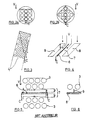
- FIGS. 2 to 5 illustrate the decrease in the average number of tubes on which condensate flows. This can be done by special arrangements of the tubes illustrated in FIGS. 2 and 3.
- FIG. 1 In the heat exchanger shown in FIG. 1 as an example of an apparatus where the invention can be applied, there is a distinction between an inlet chamber 1 and an outlet chamber 2 of the refrigerant. Between the two chambers, the refrigerant passes through a bundle of tubes 3 outside which the gases to be condensed circulate in an enclosure 3a.
- the tubes 3 are supported by support plates and / or intermediate support grids 3b.
- V denotes steam and C denotes condensate.
- FIG. 3 illustrates another geometrical arrangement of the tubes, called tangential tracing in the tube zone designated 4.
- the tangential path of the condensate is designated C.
- the reduction in the average number of tubes on which the condensates flow can also be obtained by intercepting the condensates by collecting plates either in an existing groove as shown in FIG. 4, or in a groove created in the mass of the tubes in view of the insertion of the sheets, as shown in Figure 5.
- the reference notation 6 designates the collecting sheet
- 7 designates the gas access groove
- 8 the tube bundle (s).
- the groove 7 created in the mass of the tubes for the insertion of a tube 6 does not have a primary function of supplying steam.
- the thickness of the sheets and their fixing conditions mean that there is often a significant distance d (FIG. 5) between them and the nearest plies of tubes.
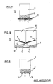
- FIGS. 7 to 9 illustrate another means used by the prior art to reduce as much as possible the sub-cooling of the condensate by carrying out a posterior heating / degassing.
- 8 denotes a bundle of tubes
- 10 denotes a perforated plate collecting the condensates which thus fall in fine C
- the notation V indicates steam.
- the invention aims to remedy the drawbacks of the prior art, in other words the partial lack of efficiency of the tube bundle due to excessive thicknesses of condensate film.
- the condensing apparatus for the replacement of at least part of a downward oblique row of tubes with profiled elements for collecting and discharging the condensates which are each offset in the same direction. relative to the upper neighboring element.
- the invention consists in substituting for a certain number of successive tubes in an appropriate alignment an equivalent number of judiciously profiled elements 20 (hereinafter called “profiles") and arranged in cascade, the shape of which allows them to be threaded through the plates - tube supports and / or support grids in a manner similar to that of tubes.
- the profiles are threaded through openings 21 which are either preferably identical to those through which the tubes pass and regularly located in all of the openings, or of any shape and located approximately at the location which one or more several openings for tubes regularly located in the bundle. It may in particular be the perforated frame of a metal plate or the mesh of a grid.
- the profiles 20 are aligned directly one below the other and each offset from the next in the same direction.
- Each profile 20 of an aligned set of profiles collects the condensates of the upper profile (except for the first profile of the alignment) and of upper tubes 3, and sends them to the lower profile.
- the condensates therefore drop in cascade from profile to profile.
- the systematic displacement of the upper profiles to the lower profiles in the same direction makes it possible to sweep a large width of the bundle of tubes and to evacuate the condensates of a multitude of tubes outside the bundle.
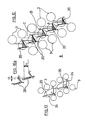
- the profiles according to the invention have three characteristic edges or lines, designated D, R and G (see FIGS. 10 and 11).
- D is a so-called discharge edge, it is the external edge of the profile through which the condensate will fall in cascade on the lower profiles. It is therefore on the side which overhangs the lower profile, offset, that is to say on the side of the offset of the profiles, side situated in the lateral direction of the evacuation of the condensates.
- G is the upper edge of the profile, called the guard, which has a double role of guard, respectively with respect to the collection of condensates from the upper profile and with respect to the fall of the condensates towards the lower profile.
- the lateral position of the edge G of any profile P is such that, given the offset of the profiles (offset sufficiently small so that there is a vertical overlap ch of the profiles), the condensates which fall from the upper profile are practically all collected between edges G and D of this profile.
- edge G The situation along the vertical of edge G is such that it prevents any overflow of the condensates collected between G and D by edge G on the side opposite to D, that is to say outside the alignment of the profiles. , which would return the condensate on the tubes, which we specifically want to avoid.
- Ga designates the guard height.
- R are one or both extreme edges or extreme horizontal straight lines of the profile located on the side opposite D at the minimum distance from the neighboring tubes. Depending on the geometry of the profile there are one or two side tubes to consider; this is how there can be 1 or 2 R points per profile.
- the external surface of the profile is, at least over a certain extent, similar to that of a tube, the place where the distance is the shortest between this surface and the two adjacent tube (s) can be a horizontal generator of this cylindrical surface and not an edge. This is the case of the rounded profile d shown in FIG. 11.
- FIG. 11 represents a device for collecting the condensates in which five variants ("a” to "e") are shown by way of examples with the profiles of FIG. 10. All these profiles are part of the normal tubular space of the bundle of tubes 8.
- FIG. 12 represents, among other things, a variant of the condensate collection device where, in its final position, the edge D of the profile f projects beyond the normal tubular space of the bundle of tubes.
- the distance between any two points of the periphery of any section of the profile between two support plates or support grids may not be greater the diameter of these openings.
- the profiles must be provided with a notch corresponding to the projection of the profile outside the tubular space.
- the profile After longitudinal threading, the profile is pushed sideways and pivoted so that its notches wedge in the support plates or support grids.
- the openings of the profiles in the support plates or support grids are still circular, but their diameter is different from that of the openings for the tubes, and / or their positions are different from those which the openings would have for tubes regularly positioned in the bundle.
- FIG. 12 also shows a profile g similar to the profile f, but devoid of a notch and therefore supported by support plates whose opening corresponding to these profiles is not exactly at the location that the openings would have 21 for tubes regularly located in the bundle, in this case in openings 22 of larger diameter.
- the profiles are located in oblong openings 24 whose width is equal to the diameter of the openings for the tubes and which extends in length over at least two successive tubes ( either over a length equal to 2 tube diameters + 1 distance between tubes).
- This variant is however probably slightly worse than the previous ones, but this drawback could be offset by a lower cost.
- FIG. 14 schematically illustrates the invention, in the context of a bundle of tubes condensing water vapor at the exhaust of a turbine. It should be noted that the shape of the beam is schematic and purely indicative. It does not correspond to a specific device on the market.
- V denotes the vapor
- I the incondensables
- A in an enlarged detail
- C the condensates
- 25 the extraction zone of the incondensables
- ASP their suction
- the geometries of the profiles fulfilling these conditions are multiple and can be obtained, for example, either from standard laminates, or by forming thin sheets (stretching; stamping; bending; ).
Landscapes
- Engineering & Computer Science (AREA)
- Mechanical Engineering (AREA)
- General Engineering & Computer Science (AREA)
- Vaporization, Distillation, Condensation, Sublimation, And Cold Traps (AREA)
- Heat-Exchange Devices With Radiators And Conduit Assemblies (AREA)
- Sampling And Sample Adjustment (AREA)
- Physical Or Chemical Processes And Apparatus (AREA)
- Fixed Capacitors And Capacitor Manufacturing Machines (AREA)
- Executing Machine-Instructions (AREA)
- Oscillators With Electromechanical Resonators (AREA)
- Cyclones (AREA)
- Industrial Gases (AREA)
Priority Applications (1)
| Application Number | Priority Date | Filing Date | Title |
|---|---|---|---|
| AT90870008T ATE75842T1 (de) | 1989-01-25 | 1990-01-17 | Kondensator. |
Applications Claiming Priority (2)
| Application Number | Priority Date | Filing Date | Title |
|---|---|---|---|
| BE8900076 | 1989-01-25 | ||
| BE8900076A BE1002785A3 (fr) | 1989-01-25 | 1989-01-25 | Collecte et rechauffage de condensats. |
Publications (2)
| Publication Number | Publication Date |
|---|---|
| EP0380462A1 true EP0380462A1 (de) | 1990-08-01 |
| EP0380462B1 EP0380462B1 (de) | 1992-05-06 |
Family
ID=3883976
Family Applications (1)
| Application Number | Title | Priority Date | Filing Date |
|---|---|---|---|
| EP90870008A Expired - Lifetime EP0380462B1 (de) | 1989-01-25 | 1990-01-17 | Kondensator |
Country Status (10)
| Country | Link |
|---|---|
| US (1) | US4974669A (de) |
| EP (1) | EP0380462B1 (de) |
| AT (1) | ATE75842T1 (de) |
| BE (1) | BE1002785A3 (de) |
| DE (1) | DE69000084D1 (de) |
| ES (1) | ES2031020T3 (de) |
| FI (1) | FI900380A7 (de) |
| GR (1) | GR3004546T3 (de) |
| MA (1) | MA21734A1 (de) |
| ZA (1) | ZA90537B (de) |
Cited By (1)
| Publication number | Priority date | Publication date | Assignee | Title |
|---|---|---|---|---|
| EP1139051A3 (de) * | 2000-03-31 | 2003-09-17 | ALSTOM (Switzerland) Ltd | Kondensator |
Families Citing this family (2)
| Publication number | Priority date | Publication date | Assignee | Title |
|---|---|---|---|---|
| TWI292467B (en) * | 2004-05-28 | 2008-01-11 | Toshiba Kk | Steam condenser |
| US9016354B2 (en) * | 2008-11-03 | 2015-04-28 | Mitsubishi Hitachi Power Systems, Ltd. | Method for cooling a humid gas and a device for the same |
Citations (4)
| Publication number | Priority date | Publication date | Assignee | Title |
|---|---|---|---|---|
| DE263464C (de) * | 1900-01-01 | |||
| GB191376A (en) * | 1922-01-05 | 1924-01-31 | Escher Wyss Maschf Ag | Improvements in or relating to surface condensers |
| FR1472838A (fr) * | 1966-03-30 | 1967-03-10 | Licentia Gmbh | Dispositif pour l'amélioration de la transmission de la chaleur dans des échangeurs thermiques à faisceaux de tubes |
| EP0109603A1 (de) * | 1982-11-22 | 1984-05-30 | Siemens Aktiengesellschaft | Austreiber |
Family Cites Families (7)
| Publication number | Priority date | Publication date | Assignee | Title |
|---|---|---|---|---|
| FR497261A (fr) * | 1918-09-28 | 1919-12-02 | Sulzer Ag | Gouttière pour tuyauteries d'installations frigorifiques |
| US1711332A (en) * | 1926-06-23 | 1929-04-30 | Firm Ag Der Maschinenfabriken | Surface condenser |
| US1887313A (en) * | 1931-02-26 | 1932-11-08 | Lester U Larkin | Refrigerated show case |
| DE1147246B (de) * | 1956-07-14 | 1963-04-18 | Magdalena Graf Kotthaus | Kuehlelement fuer Kuehlvitrinen |
| US3306071A (en) * | 1965-08-26 | 1967-02-28 | Earl F Holyfield | Cooling coil with condensate director |
| US3868830A (en) * | 1973-08-31 | 1975-03-04 | Nasa | Condensate removal device for heat exchanger |
| US4548262A (en) * | 1983-03-31 | 1985-10-22 | Hull Francis R | Condensing gas-to-gas heat exchanger |
-
1989
- 1989-01-25 BE BE8900076A patent/BE1002785A3/fr not_active IP Right Cessation
-
1990
- 1990-01-17 EP EP90870008A patent/EP0380462B1/de not_active Expired - Lifetime
- 1990-01-17 US US07/466,517 patent/US4974669A/en not_active Expired - Fee Related
- 1990-01-17 DE DE9090870008T patent/DE69000084D1/de not_active Expired - Fee Related
- 1990-01-17 ES ES199090870008T patent/ES2031020T3/es not_active Expired - Fee Related
- 1990-01-17 AT AT90870008T patent/ATE75842T1/de not_active IP Right Cessation
- 1990-01-22 MA MA21995A patent/MA21734A1/fr unknown
- 1990-01-24 FI FI900380A patent/FI900380A7/fi not_active IP Right Cessation
- 1990-01-25 ZA ZA90537A patent/ZA90537B/xx unknown
-
1992
- 1992-05-08 GR GR920400890T patent/GR3004546T3/el unknown
Patent Citations (4)
| Publication number | Priority date | Publication date | Assignee | Title |
|---|---|---|---|---|
| DE263464C (de) * | 1900-01-01 | |||
| GB191376A (en) * | 1922-01-05 | 1924-01-31 | Escher Wyss Maschf Ag | Improvements in or relating to surface condensers |
| FR1472838A (fr) * | 1966-03-30 | 1967-03-10 | Licentia Gmbh | Dispositif pour l'amélioration de la transmission de la chaleur dans des échangeurs thermiques à faisceaux de tubes |
| EP0109603A1 (de) * | 1982-11-22 | 1984-05-30 | Siemens Aktiengesellschaft | Austreiber |
Cited By (1)
| Publication number | Priority date | Publication date | Assignee | Title |
|---|---|---|---|---|
| EP1139051A3 (de) * | 2000-03-31 | 2003-09-17 | ALSTOM (Switzerland) Ltd | Kondensator |
Also Published As
| Publication number | Publication date |
|---|---|
| FI900380A0 (fi) | 1990-01-24 |
| GR3004546T3 (de) | 1993-04-28 |
| MA21734A1 (fr) | 1990-10-01 |
| ZA90537B (en) | 1990-10-31 |
| DE69000084D1 (de) | 1992-06-11 |
| BE1002785A3 (fr) | 1991-06-11 |
| ES2031020T3 (es) | 1992-11-16 |
| ATE75842T1 (de) | 1992-05-15 |
| FI900380A7 (fi) | 1990-07-26 |
| US4974669A (en) | 1990-12-04 |
| EP0380462B1 (de) | 1992-05-06 |
Similar Documents
| Publication | Publication Date | Title |
|---|---|---|
| EP3405723B1 (de) | Kondensationswärmetauscher mit einer wärmetauschervorrichtung | |
| WO2004016995A1 (fr) | Echangeur de chaleur a condensation a double faisceau de tubes | |
| FR2704303A3 (fr) | Procédé pour la combustion d'ordures sur une grille de combustion ainsi que grille pour l'exécution du procédé et plaque de grille pour la réalisation d'une pareille grille. | |
| FR2913105A1 (fr) | "echangeur de chaleur a condensation comprenant deux faisceaux primaires et un faisceau secondaire" | |
| FR3053452A1 (fr) | Echangeur de chaleur comprenant un dispositif de distribution d'un melange liquide/gaz | |
| EP0380462B1 (de) | Kondensator | |
| EP1179724B1 (de) | Wärmetauscher mit mehrfachen Wärmeaustauschblöcken mit Flüssigkeitsendkammer mit gleichmässiger Verteilung und Verdampfer-Kondensator mit demselben | |
| LU82393A1 (fr) | Echangeur de chaleur a enceinte en spirale | |
| EP1366326B1 (de) | Kondensierender wärmetauscher für einen kessel | |
| EP0738862A1 (de) | Wärmetauscher mit gelöteten Platten und entsprechendes Verfahren zur Behandlung einer zweiphasigen Flüssigkeit | |
| EP1582812B1 (de) | Verbrennungsrost mit wassergekühlten, stationären Stufen | |
| FR2811416A1 (fr) | Echangeur de chaleur du type a deux voies d'ecoulement de fluide | |
| EP0078207A2 (de) | Vorrichtungen zur Rückgewinnung von Kalorien aus Abgasen von Heizungsanlagen | |
| EP1704379A1 (de) | Reinigungsmittel umfassender wärmetauscher | |
| FR2532404A1 (fr) | Fond de chambre de combustion pour chaudiere a couche tourbillonnante | |
| EP2487443A1 (de) | Kondensator zum optimierten Wärmeaustausch und Installation zum Beheizen von Flüssigkeiten die dieser enthält | |
| EP0051036B1 (de) | Oberflächenwärmetauscher zur Wärmerückgewinnung | |
| FR2770625A1 (fr) | Element echangeur de chaleur a haut rendement destine a constituer le corps de chauffe d'une chaudiere sectionnable | |
| FR2895788A1 (fr) | Echangeur de chaleur a plaques du type condenseur a drainage preferentiel | |
| FR3151082A3 (fr) | Procédé de fabrication d’un échangeur comprenant des passages dotés d’au moins un organe de support et échangeur fabriqué par un tel procédé | |
| FR2868515A1 (fr) | Module de grille pour four d'incineration des ordures menageres | |
| BE572271A (de) | ||
| BE569725A (de) | ||
| FR3074275A1 (fr) | Echangeur de chaleur | |
| BE551685A (de) |
Legal Events
| Date | Code | Title | Description |
|---|---|---|---|
| PUAI | Public reference made under article 153(3) epc to a published international application that has entered the european phase |
Free format text: ORIGINAL CODE: 0009012 |
|
| AK | Designated contracting states |
Kind code of ref document: A1 Designated state(s): AT BE CH DE DK ES FR GB GR IT LI LU NL SE |
|
| 17P | Request for examination filed |
Effective date: 19900828 |
|
| 17Q | First examination report despatched |
Effective date: 19910523 |
|
| GRAA | (expected) grant |
Free format text: ORIGINAL CODE: 0009210 |
|
| ITF | It: translation for a ep patent filed | ||
| AK | Designated contracting states |
Kind code of ref document: B1 Designated state(s): AT BE CH DE DK ES FR GB GR IT LI LU NL SE |
|
| PG25 | Lapsed in a contracting state [announced via postgrant information from national office to epo] |
Ref country code: SE Effective date: 19920506 Ref country code: DK Effective date: 19920506 Ref country code: AT Effective date: 19920506 |
|
| REF | Corresponds to: |
Ref document number: 75842 Country of ref document: AT Date of ref document: 19920515 Kind code of ref document: T |
|
| REF | Corresponds to: |
Ref document number: 69000084 Country of ref document: DE Date of ref document: 19920611 |
|
| GBT | Gb: translation of ep patent filed (gb section 77(6)(a)/1977) | ||
| REG | Reference to a national code |
Ref country code: GR Ref legal event code: FG4A Free format text: 3004546 |
|
| PG25 | Lapsed in a contracting state [announced via postgrant information from national office to epo] |
Ref country code: LU Free format text: LAPSE BECAUSE OF NON-PAYMENT OF DUE FEES Effective date: 19930131 |
|
| PLBE | No opposition filed within time limit |
Free format text: ORIGINAL CODE: 0009261 |
|
| STAA | Information on the status of an ep patent application or granted ep patent |
Free format text: STATUS: NO OPPOSITION FILED WITHIN TIME LIMIT |
|
| 26N | No opposition filed | ||
| ITPR | It: changes in ownership of a european patent |
Owner name: CESSIONE;SOBELCO S.A. |
|
| REG | Reference to a national code |
Ref country code: FR Ref legal event code: TP |
|
| REG | Reference to a national code |
Ref country code: GB Ref legal event code: 732E |
|
| NLS | Nl: assignments of ep-patents |
Owner name: SOBELCO S.A. TE BRUSSEL, BELGIE. |
|
| REG | Reference to a national code |
Ref country code: ES Ref legal event code: PC2A Owner name: SOBELCO S.A. |
|
| REG | Reference to a national code |
Ref country code: CH Ref legal event code: PUE Owner name: SOBELCO S.A. |
|
| PGFP | Annual fee paid to national office [announced via postgrant information from national office to epo] |
Ref country code: GR Payment date: 19941130 Year of fee payment: 6 |
|
| PGFP | Annual fee paid to national office [announced via postgrant information from national office to epo] |
Ref country code: GB Payment date: 19950106 Year of fee payment: 6 |
|
| PGFP | Annual fee paid to national office [announced via postgrant information from national office to epo] |
Ref country code: CH Payment date: 19950131 Year of fee payment: 6 |
|
| PGFP | Annual fee paid to national office [announced via postgrant information from national office to epo] |
Ref country code: FR Payment date: 19951219 Year of fee payment: 7 |
|
| PGFP | Annual fee paid to national office [announced via postgrant information from national office to epo] |
Ref country code: BE Payment date: 19960110 Year of fee payment: 7 |
|
| PGFP | Annual fee paid to national office [announced via postgrant information from national office to epo] |
Ref country code: ES Payment date: 19960115 Year of fee payment: 7 |
|
| PG25 | Lapsed in a contracting state [announced via postgrant information from national office to epo] |
Ref country code: GB Effective date: 19960117 |
|
| PG25 | Lapsed in a contracting state [announced via postgrant information from national office to epo] |
Ref country code: LI Effective date: 19960131 Ref country code: CH Effective date: 19960131 |
|
| PGFP | Annual fee paid to national office [announced via postgrant information from national office to epo] |
Ref country code: NL Payment date: 19960131 Year of fee payment: 7 Ref country code: DE Payment date: 19960131 Year of fee payment: 7 |
|
| PG25 | Lapsed in a contracting state [announced via postgrant information from national office to epo] |
Ref country code: GR Free format text: THE PATENT HAS BEEN ANNULLED BY A DECISION OF A NATIONAL AUTHORITY Effective date: 19960731 |
|
| GBPC | Gb: european patent ceased through non-payment of renewal fee |
Effective date: 19960117 |
|
| REG | Reference to a national code |
Ref country code: CH Ref legal event code: PL |
|
| REG | Reference to a national code |
Ref country code: GR Ref legal event code: MM2A Free format text: 3004546 |
|
| PG25 | Lapsed in a contracting state [announced via postgrant information from national office to epo] |
Ref country code: ES Free format text: LAPSE BECAUSE OF NON-PAYMENT OF DUE FEES Effective date: 19970118 |
|
| PG25 | Lapsed in a contracting state [announced via postgrant information from national office to epo] |
Ref country code: BE Effective date: 19970131 |
|
| BERE | Be: lapsed |
Owner name: S.A. SOBELCO Effective date: 19970131 |
|
| PG25 | Lapsed in a contracting state [announced via postgrant information from national office to epo] |
Ref country code: NL Effective date: 19970801 |
|
| PG25 | Lapsed in a contracting state [announced via postgrant information from national office to epo] |
Ref country code: FR Effective date: 19970930 |
|
| NLV4 | Nl: lapsed or anulled due to non-payment of the annual fee |
Effective date: 19970801 |
|
| PG25 | Lapsed in a contracting state [announced via postgrant information from national office to epo] |
Ref country code: DE Effective date: 19971001 |
|
| REG | Reference to a national code |
Ref country code: FR Ref legal event code: ST |
|
| REG | Reference to a national code |
Ref country code: ES Ref legal event code: FD2A Effective date: 19990405 |
|
| PG25 | Lapsed in a contracting state [announced via postgrant information from national office to epo] |
Ref country code: IT Free format text: LAPSE BECAUSE OF NON-PAYMENT OF DUE FEES Effective date: 20050117 |