EP0380695A1 - Dispositif de lubrification de siege de soupape dans un moteur a combustion interne - Google Patents
Dispositif de lubrification de siege de soupape dans un moteur a combustion interne Download PDFInfo
- Publication number
- EP0380695A1 EP0380695A1 EP89908523A EP89908523A EP0380695A1 EP 0380695 A1 EP0380695 A1 EP 0380695A1 EP 89908523 A EP89908523 A EP 89908523A EP 89908523 A EP89908523 A EP 89908523A EP 0380695 A1 EP0380695 A1 EP 0380695A1
- Authority
- EP
- European Patent Office
- Prior art keywords
- valve seat
- ring
- valve
- seat ring
- lubricant oil
- Prior art date
- Legal status (The legal status is an assumption and is not a legal conclusion. Google has not performed a legal analysis and makes no representation as to the accuracy of the status listed.)
- Granted
Links
Images

Classifications
-
- F—MECHANICAL ENGINEERING; LIGHTING; HEATING; WEAPONS; BLASTING
- F01—MACHINES OR ENGINES IN GENERAL; ENGINE PLANTS IN GENERAL; STEAM ENGINES
- F01M—LUBRICATING OF MACHINES OR ENGINES IN GENERAL; LUBRICATING INTERNAL COMBUSTION ENGINES; CRANKCASE VENTILATING
- F01M9/00—Lubrication means having pertinent characteristics not provided for in, or of interest apart from, groups F01M1/00 - F01M7/00
- F01M9/10—Lubrication of valve gear or auxiliaries
-
- F—MECHANICAL ENGINEERING; LIGHTING; HEATING; WEAPONS; BLASTING
- F01—MACHINES OR ENGINES IN GENERAL; ENGINE PLANTS IN GENERAL; STEAM ENGINES
- F01L—CYCLICALLY OPERATING VALVES FOR MACHINES OR ENGINES
- F01L3/00—Lift-valve, i.e. cut-off apparatus with closure members having at least a component of their opening and closing motion perpendicular to the closing faces; Parts or accessories thereof
- F01L3/22—Valve-seats not provided for in preceding subgroups of this group; Fixing of valve-seats
-
- F—MECHANICAL ENGINEERING; LIGHTING; HEATING; WEAPONS; BLASTING
- F16—ENGINEERING ELEMENTS AND UNITS; GENERAL MEASURES FOR PRODUCING AND MAINTAINING EFFECTIVE FUNCTIONING OF MACHINES OR INSTALLATIONS; THERMAL INSULATION IN GENERAL
- F16N—LUBRICATING
- F16N7/00—Arrangements for supplying oil or unspecified lubricant from a stationary reservoir or the equivalent in or on the machine or member to be lubricated
- F16N7/12—Arrangements for supplying oil or unspecified lubricant from a stationary reservoir or the equivalent in or on the machine or member to be lubricated with feed by capillary action, e.g. by wicks
Definitions
- the present invention relates to a lubricating system for a valve seat of an internal combustion engine and in particular to a system for lubricating a valve seat of a suction and exhaust valve of internal combustion engine with which a valve head is in close contact.
- a suction and exhaust valve mechanism of internal combustion engine employs the so-called poppet valve.
- lubricant oil is fed to the valve seat to prevent a wear in a valve seat surface.
- a prior art has fed lubricant oil by gravity to the valve seat through a small clearance between a valve stem and a valve guide retaining the stem.
- an internal combustion engine employs a supercharger boosting the feed pressure of air-fuel mixture fed to engine cylinder.
- the boosted feed pressure of air-fuel mixture is applied to the clearance between the valve stem of the valve and the valve guide from the downstream to the upstream of the clearance.
- lubricant oil fails to fall through the clearance from upstream to downstream so that the feed of lubricant oil to the valve seat is blocked to insufficiently lubricate the valve seat surface.
- a head of the valve when seated on the valve seat surface, receives the internal pressure in the engine cylinder so as to minutely displace while being in contact with the valve seat surface.
- the insufficient feed of lubricant oil to the valve seat surface causes wears in both the head of the valve and the valve seat surface so as to damage a gastightness of the valve, which reduces output of internal combustion engine.
- an object of the present invention is to provide a lubricating system for a valve seat of an internal combustion engine which secures to feed lubricant oil to the valve seat so as to prevent wears in the head of the valve and the valve seat surface.
- the seat ring providing the valve seat surface is made of a porous material readily containing lubricant oil
- the outer cylindrical surface of the seat ring is formed withan annular groove
- the engine cylinder head is formed withe annular groove.
- the lubricant oil which is fed through the oil passage to the annular groove is contained in porous material part of the seat ring and then produces oil film on the valve seat surface of the seat ring so as to prevent wears in the valve seat surface and the valve head.
- FIG.1 is a fragmentary section of the main part of an engine cylinder head, illustrating the lubricating system for the valve seat according to one embodiment of the present invention.
- a cylinder head 1 has a seat ring 2 fitted therewithin and providing the valve seat, i.e., a part of combustion chamber with which a head 3a of a valve 3 contacts.
- the outer cylindrical surface of a seat ring 2 is formed with an annular groove 4 along the outer circumferece thereof.
- the annular groove 4 communicates with an oil passage 5 formed in a cylinder head 1.
- the seat ring 2 is formed of a single material produced by sintering or the like process which has a mechanical strength sufficient for the valve seat and includes a porous metal structure in part.
- an annular part 6 between a valve seat surface 7 of the seat ring 2 and the annular groove 4 is of a porous metal structure.
- an oil pump or the like forcibly feeds lubricant oil through a right-hand oil passage 5 of FIG.1 into the annular groove 4 formed in the seat ring 2. Then, lubricant oil circulates through the annular groove 4 to cool the seat ring 2 and returns through a left-hand oil passage 5 of FIG.1 to an oil pan,etc. A part of the lubricant oil forcibly fed to the annular groove 4 in the seat ring 2 penetrates the part 6 made of the porous metal structure to produce lubricant oil film on the valve seat surface 7 of the seat ring 2.
- the seat ring 2 has the mechanical strength sufficient for the valve seat and the porous metal structure in part.
- the present invention is not restricted to the above embodiment.
- the annular porous metal structure constituting the part 6 may be produced separately from the seat ring 2 and fastend to the valve seat surface 7 of the seat ring 2.
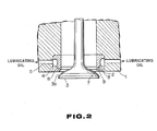
- FIG.2 is a fragmentary section of the main part of engine cylinder head, illustrating a second embodiment of the present invention.
- the same parts as those of FIG.1 will bear the same numerals.
- a part providing a valve seat surface 7 of a seat ring 2 has a porous metal structure 9 which communicates through a lubricant oil hole 8 with an annular groove 4.
- the oil pump or the like forcibly feeds lubricant oil through a right-hand oil passage 5 of FIG.2 to the annular groove 4. Then, lubricant oil circulates through the annular groove 4 to cool the seat ring 2 and returns through a left-hand oil passage 5 of FIG.2 to the oil pan, etc.
- a partof the lubricant oil forcibly fed to the annular groove 4 in the seat ring 2 penetrates the porous metal structure 9 through the lubricant oil hole 8 and is contained therein to produce lubricant oil film on the valve seat surface of the seat ring 2.
- the outer cylindrical surface of the seat ring providing the valve seat is formed with the annular groove, at least a part constituting the valve seat surface of the seat ring has the porous metal structire, and lubricant oil is fed through the groove to the part having the porous metal structure to produce lubricant oil film on the valve seat surface, so that when the valve head sits on the valve seat surface and when the valve head in a sitting position receives an intrenal pressure in the engine cylinder to deform, which causes a minute frictional displacement of the valve head, a possible metal-metal contact between the valve head and the valve seat surface will be eliminated, which prevents possible wears in both the valve head and the valve seat surface.
- the lubricating system of the present invention is applicable to a lubricating system for a valve seat of internal combustion engine required to prevent a reduction in the output of the internal combustion engine and improve the reliability of the engine.
Landscapes
- Engineering & Computer Science (AREA)
- General Engineering & Computer Science (AREA)
- Mechanical Engineering (AREA)
- Cylinder Crankcases Of Internal Combustion Engines (AREA)
- Lubrication Of Internal Combustion Engines (AREA)
Abstract
Applications Claiming Priority (2)
| Application Number | Priority Date | Filing Date | Title |
|---|---|---|---|
| JP97298/88U | 1988-07-25 | ||
| JP1988097298U JPH0219807U (fr) | 1988-07-25 | 1988-07-25 |
Publications (3)
| Publication Number | Publication Date |
|---|---|
| EP0380695A1 true EP0380695A1 (fr) | 1990-08-08 |
| EP0380695A4 EP0380695A4 (en) | 1990-12-12 |
| EP0380695B1 EP0380695B1 (fr) | 1993-01-20 |
Family
ID=14188589
Family Applications (1)
| Application Number | Title | Priority Date | Filing Date |
|---|---|---|---|
| EP89908523A Expired - Lifetime EP0380695B1 (fr) | 1988-07-25 | 1989-07-24 | Dispositif de lubrification de siege de soupape dans un moteur a combustion interne |
Country Status (5)
| Country | Link |
|---|---|
| US (1) | US5074256A (fr) |
| EP (1) | EP0380695B1 (fr) |
| JP (1) | JPH0219807U (fr) |
| KR (1) | KR900702179A (fr) |
| WO (1) | WO1990001108A1 (fr) |
Families Citing this family (9)
| Publication number | Priority date | Publication date | Assignee | Title |
|---|---|---|---|---|
| DE69628979T2 (de) * | 1995-08-18 | 2004-02-12 | Orbital Engine Co. (Australia) Pty. Ltd., Balcatta | Brennstoffeinspritzungssystem für Brennkraftmaschine |
| US6116570A (en) * | 1998-03-30 | 2000-09-12 | Siemens Automotive Corporation | Electromagnetic actuator with internal oil system and improved hydraulic lash adjuster |
| US6305459B1 (en) | 1999-08-09 | 2001-10-23 | Ford Global Technologies, Inc. | Method of making spray-formed articles using a polymeric mandrel |
| US6270849B1 (en) | 1999-08-09 | 2001-08-07 | Ford Global Technologies, Inc. | Method of manufacturing a metal and polymeric composite article |
| DE10200664A1 (de) * | 2002-01-11 | 2003-07-24 | Opel Adam Ag | Wasserdurchlässiger Ventilsitzring sowie Zylinderkopf unter Verwendung eines wasserdurchlässigen Ventilsitzringes |
| US10989146B2 (en) * | 2018-11-05 | 2021-04-27 | Caterpillar Inc. | Oil injection methods for combustion enhancement in natural gas reciprocating engines |
| US10947925B2 (en) * | 2019-06-19 | 2021-03-16 | Caterpillar Inc. | Methods for reducing oil sticking on surfaces of internal combustion engines |
| CN115053059B (zh) * | 2020-02-13 | 2023-11-14 | 川崎重工业株式会社 | 汽缸盖及其耐腐蚀性提高方法 |
| JP7882236B2 (ja) * | 2023-11-22 | 2026-06-30 | トヨタ自動車株式会社 | 燃料供給装置 |
Family Cites Families (14)
| Publication number | Priority date | Publication date | Assignee | Title |
|---|---|---|---|---|
| GB1068653A (en) * | 1965-02-25 | 1967-05-10 | Daimler Benz Ag | Preventing valve impact in a supercharged internal combustion engine |
| GB1330032A (en) * | 1971-03-30 | 1973-09-12 | County Commercial Cars Ltd | Internal combustion engines infizenza vaccine for peroral administration and a method of producing same |
| JPS52111844U (fr) * | 1976-02-19 | 1977-08-25 | ||
| JPS52111844A (en) * | 1976-03-17 | 1977-09-19 | Toyo Giken Kougiyou Kk | Method of circulating liquid in surface treating means |
| JPS52137210U (fr) * | 1976-04-14 | 1977-10-18 | ||
| JPS52137210A (en) * | 1976-05-12 | 1977-11-16 | Matsushita Electric Ind Co Ltd | Solid taking image device |
| CH612244A5 (fr) * | 1976-05-24 | 1979-07-13 | Sulzer Ag | |
| CH614014A5 (fr) * | 1977-01-28 | 1979-10-31 | Sulzer Ag | |
| US4169488A (en) * | 1977-11-23 | 1979-10-02 | Caterpillar Tractor Co. | Cooled engine valve |
| JPS5650711U (fr) * | 1979-09-28 | 1981-05-06 | ||
| JPS5650711A (en) * | 1979-09-29 | 1981-05-08 | Mitsubishi Electric Corp | Sheet thickness controller for tandem mill |
| DE3346371A1 (de) * | 1983-12-22 | 1985-07-04 | Audi AG, 8070 Ingolstadt | Vorrichtung zum schmieren der schaefte von gaswechsel-ventilen im zylinderkopf einer hubkolben-brennkraftmaschine |
| JPS61108808A (ja) * | 1984-11-01 | 1986-05-27 | Hitachi Ltd | 軸受のシ−ル構造 |
| JPS61108808U (fr) * | 1984-12-21 | 1986-07-10 |
-
1988
- 1988-07-25 JP JP1988097298U patent/JPH0219807U/ja active Pending
-
1989
- 1989-07-24 EP EP89908523A patent/EP0380695B1/fr not_active Expired - Lifetime
- 1989-07-24 WO PCT/JP1989/000736 patent/WO1990001108A1/fr not_active Ceased
- 1989-07-24 US US07/469,472 patent/US5074256A/en not_active Expired - Fee Related
- 1989-07-24 KR KR1019900700602A patent/KR900702179A/ko not_active Withdrawn
Also Published As
| Publication number | Publication date |
|---|---|
| US5074256A (en) | 1991-12-24 |
| EP0380695B1 (fr) | 1993-01-20 |
| KR900702179A (ko) | 1990-12-06 |
| EP0380695A4 (en) | 1990-12-12 |
| WO1990001108A1 (fr) | 1990-02-08 |
| JPH0219807U (fr) | 1990-02-09 |
Similar Documents
| Publication | Publication Date | Title |
|---|---|---|
| US4708102A (en) | Roller cam follower with positive lubrication | |
| US4622933A (en) | Lubricant feed system for use in the journal of a crankshaft | |
| US4184464A (en) | Recirculation groove for hydraulic lash adjuster | |
| US5273005A (en) | Enlarged shaft roller lifter with retention means | |
| US3809046A (en) | Valve guide stabilizing and sealing insert | |
| US4589383A (en) | Squeeze film rocker tip | |
| EP0030781A1 (fr) | Poussoir hydraulique pour vanne à entrainement direct | |
| US5074256A (en) | Lubricating system for a valve seat of an internal combustion engine | |
| GB1429894A (en) | Bearing lubricating devices | |
| US3998199A (en) | Supercharged internal combustion engines | |
| US4458643A (en) | Lubricating oil feeding device for fuel injection pumps | |
| US5307778A (en) | Fuel injection pump for internal combustion engines | |
| EP0552369A1 (fr) | Dispositif hydraulique de reglage de jeu muni d'un event | |
| JPS58113511A (ja) | 油圧ラツシユアジヤスタ | |
| JPH0263082B2 (fr) | ||
| JPH0441205Y2 (fr) | ||
| US20020040734A1 (en) | One- way control valve | |
| US4343377A (en) | Crank mechanism lubricating system | |
| JPH0768932B2 (ja) | 燃料噴射ポンプ | |
| EP0467680A1 (fr) | Buse d'injection de carburant pour moteurs à combustion interne | |
| EP0745758A1 (fr) | Dispositif à soupapes soulevantes | |
| JP4005934B2 (ja) | 内燃機関用油圧ラッシュアジャスタ | |
| JP2007218282A (ja) | 密封装置 | |
| EP0117218B1 (fr) | Disposition de montage pour cylindre d'injection dans la boîte d'une pompe d'injection | |
| JPH109400A (ja) | バルブステムシール |
Legal Events
| Date | Code | Title | Description |
|---|---|---|---|
| PUAI | Public reference made under article 153(3) epc to a published international application that has entered the european phase |
Free format text: ORIGINAL CODE: 0009012 |
|
| 17P | Request for examination filed |
Effective date: 19900420 |
|
| AK | Designated contracting states |
Kind code of ref document: A1 Designated state(s): DE GB |
|
| A4 | Supplementary search report drawn up and despatched |
Effective date: 19901023 |
|
| AK | Designated contracting states |
Kind code of ref document: A4 Designated state(s): DE GB |
|
| 17Q | First examination report despatched |
Effective date: 19910425 |
|
| GRAA | (expected) grant |
Free format text: ORIGINAL CODE: 0009210 |
|
| AK | Designated contracting states |
Kind code of ref document: B1 Designated state(s): DE GB |
|
| REF | Corresponds to: |
Ref document number: 68904547 Country of ref document: DE Date of ref document: 19930304 |
|
| PLBE | No opposition filed within time limit |
Free format text: ORIGINAL CODE: 0009261 |
|
| STAA | Information on the status of an ep patent application or granted ep patent |
Free format text: STATUS: NO OPPOSITION FILED WITHIN TIME LIMIT |
|
| 26N | No opposition filed | ||
| PGFP | Annual fee paid to national office [announced via postgrant information from national office to epo] |
Ref country code: GB Payment date: 19960715 Year of fee payment: 8 |
|
| PGFP | Annual fee paid to national office [announced via postgrant information from national office to epo] |
Ref country code: DE Payment date: 19960802 Year of fee payment: 8 |
|
| PG25 | Lapsed in a contracting state [announced via postgrant information from national office to epo] |
Ref country code: GB Free format text: LAPSE BECAUSE OF NON-PAYMENT OF DUE FEES Effective date: 19970724 |
|
| GBPC | Gb: european patent ceased through non-payment of renewal fee |
Effective date: 19970724 |
|
| PG25 | Lapsed in a contracting state [announced via postgrant information from national office to epo] |
Ref country code: DE Free format text: LAPSE BECAUSE OF NON-PAYMENT OF DUE FEES Effective date: 19980401 |