EP0380697A1 - Procede de retour au point de depart - Google Patents
Procede de retour au point de depart Download PDFInfo
- Publication number
- EP0380697A1 EP0380697A1 EP89908853A EP89908853A EP0380697A1 EP 0380697 A1 EP0380697 A1 EP 0380697A1 EP 89908853 A EP89908853 A EP 89908853A EP 89908853 A EP89908853 A EP 89908853A EP 0380697 A1 EP0380697 A1 EP 0380697A1
- Authority
- EP
- European Patent Office
- Prior art keywords
- point
- signal
- return
- scale
- linear scale
- Prior art date
- Legal status (The legal status is an assumption and is not a legal conclusion. Google has not performed a legal analysis and makes no representation as to the accuracy of the status listed.)
- Withdrawn
Links
Images


Classifications
-
- G—PHYSICS
- G05—CONTROLLING; REGULATING
- G05B—CONTROL OR REGULATING SYSTEMS IN GENERAL; FUNCTIONAL ELEMENTS OF SUCH SYSTEMS; MONITORING OR TESTING ARRANGEMENTS FOR SUCH SYSTEMS OR ELEMENTS
- G05B19/00—Program-control systems
- G05B19/02—Program-control systems electric
- G05B19/18—Numerical control [NC], i.e. automatically operating machines, in particular machine tools, e.g. in a manufacturing environment, so as to execute positioning, movement or co-ordinated operations by means of program data in numerical form
- G05B19/19—Numerical control [NC], i.e. automatically operating machines, in particular machine tools, e.g. in a manufacturing environment, so as to execute positioning, movement or co-ordinated operations by means of program data in numerical form characterised by positioning or contouring control systems, e.g. to control position from one programmed point to another or to control movement along a programmed continuous path
- G05B19/21—Numerical control [NC], i.e. automatically operating machines, in particular machine tools, e.g. in a manufacturing environment, so as to execute positioning, movement or co-ordinated operations by means of program data in numerical form characterised by positioning or contouring control systems, e.g. to control position from one programmed point to another or to control movement along a programmed continuous path using an incremental digital measuring device
- G05B19/23—Numerical control [NC], i.e. automatically operating machines, in particular machine tools, e.g. in a manufacturing environment, so as to execute positioning, movement or co-ordinated operations by means of program data in numerical form characterised by positioning or contouring control systems, e.g. to control position from one programmed point to another or to control movement along a programmed continuous path using an incremental digital measuring device for point-to-point control
- G05B19/231—Numerical control [NC], i.e. automatically operating machines, in particular machine tools, e.g. in a manufacturing environment, so as to execute positioning, movement or co-ordinated operations by means of program data in numerical form characterised by positioning or contouring control systems, e.g. to control position from one programmed point to another or to control movement along a programmed continuous path using an incremental digital measuring device for point-to-point control the positional error is used to control continuously the servomotor according to its magnitude
-
- G—PHYSICS
- G05—CONTROLLING; REGULATING
- G05B—CONTROL OR REGULATING SYSTEMS IN GENERAL; FUNCTIONAL ELEMENTS OF SUCH SYSTEMS; MONITORING OR TESTING ARRANGEMENTS FOR SUCH SYSTEMS OR ELEMENTS
- G05B19/00—Program-control systems
- G05B19/02—Program-control systems electric
- G05B19/18—Numerical control [NC], i.e. automatically operating machines, in particular machine tools, e.g. in a manufacturing environment, so as to execute positioning, movement or co-ordinated operations by means of program data in numerical form
- G05B19/416—Numerical control [NC], i.e. automatically operating machines, in particular machine tools, e.g. in a manufacturing environment, so as to execute positioning, movement or co-ordinated operations by means of program data in numerical form characterised by control of velocity, acceleration or deceleration
-
- G—PHYSICS
- G05—CONTROLLING; REGULATING
- G05B—CONTROL OR REGULATING SYSTEMS IN GENERAL; FUNCTIONAL ELEMENTS OF SUCH SYSTEMS; MONITORING OR TESTING ARRANGEMENTS FOR SUCH SYSTEMS OR ELEMENTS
- G05B2219/00—Program-control systems
- G05B2219/30—Nc systems
- G05B2219/50—Machine tool, machine tool null till machine tool work handling
- G05B2219/50042—Return to origin, reference point, zero point, homing
Definitions
- This invention relates to a reference-point return method and, more particularly, to a reference-point return method for returning a machine tool table or the like to a predetermined reference point by an output signal from a linear scale.
- a reference-point return method is available for moving a machine tool in the direction of a predetermined reference point, reducing the reference-point return velocity in response to generation of a deceleration signal, and stopping a movable element in response to an initial one-revolution signal, which is indicative of one revolution of a motor, following the generation of a signal indicating the proximity of the reference point.
- Fig. 5 is a view for describing such a reference-point return method.
- a movable element (table) TB of a machine is provided with a limit switch LS, and a stationary portion MC of the machine is provided with a reference-point return dog DOG in the vicinity of the machine reference point.
- the movable element TB of the machine is moved toward the reference point at a rapid-traverse velocity V H .
- a limit signal LSS makes a transition from "1" (high level) to "0" (low level), as shown in Fig. 4.
- the reference-point return velocity is reduced in response to the negative-going transition (deceleration signal) of the limit signal LSS.
- the limit switch LS parts from the DG and the limit signal LSS reverts from "0" to "1".
- the traveling velocity at this time is V L .
- the limit signal LSS reverts from “0" to "1” (rises)
- the movable element TB of the machine subsequently moves toward the reference point at the velocity V L and stops in response to generation of an initial one-revolution signal ORS, which is indicative of one-revolution of a motor, following the occurrence of the positive-going transition (reference-point proximity signal) of the limit signal LSS.
- OTA in Fig. 4 represents an over-travel area
- first, second and third areas AI, AII and AIII represent an area on the over-travel side, a reference-point proximity area, and a working area, respectively.
- a mechanical switch such as the limit switch LS switched at the predetermined position is required.
- the accuracy of the reference-point return operation is greatly influenced by the mounting precision and operating precision of the switch.
- the prior art is such that reference-point return control is performed by making joint use of this signal and the motor one-revolution signal generated by a linear scale or rotary encoder originally mounted on an NC machine tool.
- an object of the present invention is to provide a reference-point return method in which signals indicative of a deceleration starting position and a reference-point position are generated solely by a linear scale, and without using a mechanical switch, to return a movable machine element to the reference point.
- the present invention relates to a reference-point return method for returning a movable element of a machine to a reference point using solely a linear scale, without relying upon a limit switch.
- the arrangement is such that a linear scale generates signals indicative of a deceleration starting position and a reference-point position.
- Reference-point return velocity is reduced using the signal indicating the deceleration starting position, and movement of the movable machine element is stopped in response to the signal indicative of the reference-point position. Return to the reference point is thus achieved.
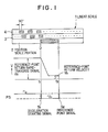
- Fig. 1 is a view for describing the general features of the present invention
- Fig. 2 is a perspective view showing the construction of a linear scale.
- numeral 1 denotes a linear scale having a position scale portion 2 for stipulating an acceleration starting position and a reference-point position, and position measurement portions 3, 4 which generate A-phase and B-phase signals for detecting position.
- Va represents a rapid-traverse velocity for return to a reference point
- Vb a velocity for return to the reference point
- S 1 a deceleration-start signal
- S 2 a reference-point position signal.
- the linear scale 1 comprises a glass-like transparent plate, and masks (the shaded portions in the drawings) for blocking the transmission of light through the glass-like transparent plate.
- a deceleration starting position D and a reference-point position 0 are set at respective ends of the mask of the position scale 2.
- the two-phase signals A, B for measuring the position of the movable machine element TB shown in Fig. 4 are generated by virtue of the mask patterns of the position measurement scale portions 3 and 4.
- the two-phase signals A and B are 90' out of phase.
- Fig. 2 is a perspective view of the operating principle and shows the construction of a linear scale.
- a light-emitting element 11 and a light-receiving element 12 are arranged to oppose each other with the linear scale 1 and a scale 13 on the light-receiving side disposed therebetween. These are arranged to detect the transmission of light through the linear scale.
- the signals S 1 , S 2 indicative of the deceleration starting position D and reference-point position 0 are generated by light which has passed through the position scale portion 2. Though only one light-emitting element and only one light-receiving element are shown, in actuality these are provided for each of the scale portions 2 through 4 and they are so arranged that the transmitted light beams will not interfere with one another.
- the linear scale 1 is secured to the stationary portion MC of the machine shown in Fig. 4, and the light-emitting element 11, light-receiving element 12 and scale 13 on the light-receiving side are provided on the movable element TB of the machine to move in unison therewith.
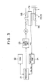
- Fig. 3 is a control block of a machine tool capable of practicing the reference-point return method of the present invention.
- Numeral 21 denotes a processor which exercises overall control, 22 a ROM storing a reference-point return control program according to the present invention, and 23 a table drive unit for rotating the motor M to drive the movable machine element TB via a ball screw BS coupled to the rotary shaft of the motor M.
- Numeral 24 denotes an interface unit for inputting the deceleration starting signal S 1 and reference-point position signal S 2 to the processor 21 using a position signal PS obtained from the light-emitting element 11 and light-receiving element 12, by way of example.
- the processor 21 performs control to effect return to the reference point by slowing the reference-point rapid-traverse velocity Va to the reference-point return velocity Vb using the deceleration starting signal S l , and stopping the movable element by the reference-point position signal 5 2 .
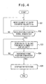
- Fig. 4 is a flowchart of reference-point return processing according to the present invention. Reference-point return control of the present invention will now be described with reference to Figs. 1 through 4.
- the processor 21 when a button on an operator's panel, not shown, is manipulated to command a reference-point return mode, the processor 21 is placed under the control of the reference-point return control program stored in the ROM 22 and executes reference-point return control, described below. Specifically, the processor 21 causes the movable machine element TB to move toward the reference point at the reference-point rapid-traverse velocity Va (step 101). When the vicinity of the reference point is reached at time t 1 , the position PS outputted by the linear scale 1 makes a transition from "1" (high level) to "0" (low level), as shown in Fig. 1. In response to this negative-going transition of the position signal, the interface unit 24 generates the deceleration starting signal S 1 (step 102).
- the processor 21 responds to the deceleration starting signal S 1 by slowing the traveling velocity to the reference-point return velocity Vb (step 103).
- the position signal PS outputted by the linear scale 1 reverts from “0" to "1” at time t 2 .
- the interface unit 24 generates the reference-point position signal S 2 (step 104).
- the processor 21 recognizes the position at which the reference-point position signal was generated as being the reference-point position, stops the rotation of the motor M and ends reference-point return control (step 105).
- the position signal PS outputted by the linear scale 1 can be replaced by one obtained by inverting this signal level, as indicated by the dashed line.
- the reference-point position can be shifted if this arrangement is adopted.
- N it is possible to set a numerical value N in advance, generate the reference-point position signal S 2 and subsequently stop the movable machine element, with the position at which N-number of the two-phase signals have been generated following generation of the signal S 2 being taken as the reference point.
- the arrangement is such that a linear scale generates signals indicative of a deceleration starting position and a reference-point position, reference-point return velocity is slowed using the signal indicating the deceleration starting position, and movement is stopped in response to the signal indicative of the reference-point position, thereby achieving return to the reference point.
- reference-point return can be performed in highly accurate fashion without using a mechanical switch.
Landscapes
- Engineering & Computer Science (AREA)
- Human Computer Interaction (AREA)
- Manufacturing & Machinery (AREA)
- Physics & Mathematics (AREA)
- General Physics & Mathematics (AREA)
- Automation & Control Theory (AREA)
- Control Of Position Or Direction (AREA)
- Transmission And Conversion Of Sensor Element Output (AREA)
Abstract
Procédé permettant de faire revenir au point de départ une pièce mécanique mobile, utilisant uniquement une échelle linéaire mais sans contacteur de fin de course. L'échelle linéaire (1) est pourvue d'une deuxième partie d'échelle (2) servant à spécifier une position de commencement de décélération et une position d'origine en plus des premières parties d'échelle (3, 4) qui produisent des signaux biphasés servant à détecter la position. Des signaux (S1, S2) représentant une position de commencement de décélération (D) et une position d'origine (O) sont produits à partir de la deuxième partie d'échelle (2), la vitesse d'avance rapide (Va) pour le retour au point de départ est décélérée jusqu'à une vitesse (Vb) de retour au point de départ en utilisant le signal de commencement de décélération (S1), et le déplacement est arrêté en réponse au signal de position d'origine (S2) pour revenir à la position d'origine.
Applications Claiming Priority (2)
| Application Number | Priority Date | Filing Date | Title |
|---|---|---|---|
| JP189263/88 | 1988-07-28 | ||
| JP63189263A JPH0239208A (ja) | 1988-07-28 | 1988-07-28 | 原点復帰方法 |
Publications (2)
| Publication Number | Publication Date |
|---|---|
| EP0380697A1 true EP0380697A1 (fr) | 1990-08-08 |
| EP0380697A4 EP0380697A4 (en) | 1991-06-05 |
Family
ID=16238381
Family Applications (1)
| Application Number | Title | Priority Date | Filing Date |
|---|---|---|---|
| EP19890908853 Withdrawn EP0380697A4 (en) | 1988-07-28 | 1989-07-26 | Method of returning to origin |
Country Status (4)
| Country | Link |
|---|---|
| US (1) | US5119004A (fr) |
| EP (1) | EP0380697A4 (fr) |
| JP (1) | JPH0239208A (fr) |
| WO (1) | WO1990001188A1 (fr) |
Families Citing this family (4)
| Publication number | Priority date | Publication date | Assignee | Title |
|---|---|---|---|---|
| JPH0634393A (ja) * | 1992-07-21 | 1994-02-08 | Fujikura Ltd | 光学式リニアエンコーダ |
| CN100378607C (zh) * | 2005-09-01 | 2008-04-02 | 广东省机械研究所 | 一种数控机床任意位置回参考点的方法 |
| JP4818697B2 (ja) * | 2005-11-28 | 2011-11-16 | アスモ株式会社 | 開閉部材制御装置 |
| DE102007038844A1 (de) * | 2007-08-16 | 2009-02-19 | Dorma Gmbh + Co. Kg | Linearantrieb für Schiebetüren oder dergleichen |
Family Cites Families (15)
| Publication number | Priority date | Publication date | Assignee | Title |
|---|---|---|---|---|
| JPS5016186A (fr) * | 1973-06-14 | 1975-02-20 | ||
| JPS547078A (en) * | 1977-06-16 | 1979-01-19 | Oki Electric Ind Co Ltd | Automatic positioning method to inherent position of machine in numerical control |
| JPS5776607A (en) * | 1980-10-30 | 1982-05-13 | Fanuc Ltd | Numeric control system |
| JPS58206366A (ja) * | 1982-05-27 | 1983-12-01 | Toshiba Mach Co Ltd | Nc機械の原点復帰処理方法 |
| JPH0627653B2 (ja) * | 1983-11-08 | 1994-04-13 | 株式会社日立製作所 | 位置、速度検出方法及び装置 |
| AT396631B (de) * | 1984-07-06 | 1993-10-25 | Rsf Elektronik Gmbh | Inkrementales messsystem |
| JPS6123211A (ja) * | 1984-07-12 | 1986-01-31 | Fanuc Ltd | 原点復帰方式 |
| JPH07101373B2 (ja) * | 1985-01-29 | 1995-11-01 | 富士通株式会社 | キャリッジのホームポジション初期化方式 |
| JPS62144024A (ja) * | 1985-12-18 | 1987-06-27 | Mitsubishi Electric Corp | 変位検出装置 |
| JP2558252B2 (ja) * | 1986-02-19 | 1996-11-27 | フアナツク株式会社 | 原点復帰方法 |
| DE3709129A1 (de) * | 1986-03-26 | 1987-11-12 | Mitsubishi Electric Corp | Numerische steuervorrichtung |
| US4789874A (en) * | 1987-07-23 | 1988-12-06 | Hewlett-Packard Company | Single channel encoder system |
| DE3844705C2 (fr) * | 1987-09-30 | 1992-06-17 | Kabushiki Kaisha Okuma Tekkosho, Nagoya, Aichi, Jp | |
| JP2658635B2 (ja) * | 1991-07-17 | 1997-09-30 | 日産自動車株式会社 | 射出成形装置 |
| JPH06298217A (ja) * | 1993-04-13 | 1994-10-25 | Nippon Steel Corp | 梱包用鋼板の供給装置 |
-
1988
- 1988-07-28 JP JP63189263A patent/JPH0239208A/ja active Pending
-
1989
- 1989-07-26 EP EP19890908853 patent/EP0380697A4/en not_active Withdrawn
- 1989-07-26 WO PCT/JP1989/000743 patent/WO1990001188A1/fr not_active Ceased
- 1989-07-26 US US07/474,753 patent/US5119004A/en not_active Expired - Fee Related
Also Published As
| Publication number | Publication date |
|---|---|
| JPH0239208A (ja) | 1990-02-08 |
| EP0380697A4 (en) | 1991-06-05 |
| WO1990001188A1 (fr) | 1990-02-08 |
| US5119004A (en) | 1992-06-02 |
Similar Documents
| Publication | Publication Date | Title |
|---|---|---|
| JP3341933B2 (ja) | 加工物表面の走査方法および走査装置 | |
| US4096770A (en) | Method and apparatus for modifying the position of a machine slide to compensate for different following errors | |
| CA1214850A (fr) | Correcteur automatique d'erreurs dynamiques | |
| JPH03190652A (ja) | 非接触ならい制御装置 | |
| GB2088087A (en) | Position control system | |
| KR840000862B1 (ko) | 모방 제어 방식 | |
| EP0510204A4 (fr) | Procede d'evaluation de la precision du fonctionnement d'une machine a commande numerique. | |
| WO1993000620A1 (fr) | Systeme de commande pour machine-outil | |
| US5119004A (en) | Reference-point return method | |
| US6052628A (en) | Method and system for continuous motion digital probe routing | |
| Jie-chi et al. | Two dimensional tracing and measurement using touch trigger probes | |
| US3728607A (en) | Phase analog numerical control system employing a laser digitized position feedback | |
| JP2845730B2 (ja) | 位置制御システムの位置情報判別装置及びその判別方法 | |
| US3980938A (en) | Scale control device for use in profiling machine tool | |
| KR890001353B1 (ko) | 수치 제어장치 | |
| KR920003740B1 (ko) | 3차원 직교좌표형 고속정밀측정기 | |
| SU898387A1 (ru) | Устройство дл программного управлени станком | |
| JPH083733B2 (ja) | 数値制御装置の原点復帰方式 | |
| JP2896910B2 (ja) | 工作機械における可動部の原点復帰方法 | |
| JPS628486Y2 (fr) | ||
| SU1024225A1 (ru) | Способ позиционировани металлорежущего инструмента | |
| SU798716A2 (ru) | Система двухкоординатного программногоупРАВлЕНи C КОРРЕКциЕй пРОгРАММы | |
| JPH0233122Y2 (fr) | ||
| SU434379A1 (ru) | УСТРОЙСТВО ДЛЯ КОРРЕКЦИИ ПОЛОЖЕНИЯ ИСПОЛНИТЕЛЬНОГО ОРГАНАWl( | |
| JPH0375515A (ja) | 駆動装置 |
Legal Events
| Date | Code | Title | Description |
|---|---|---|---|
| PUAI | Public reference made under article 153(3) epc to a published international application that has entered the european phase |
Free format text: ORIGINAL CODE: 0009012 |
|
| 17P | Request for examination filed |
Effective date: 19900417 |
|
| AK | Designated contracting states |
Kind code of ref document: A1 Designated state(s): DE FR GB |
|
| A4 | Supplementary search report drawn up and despatched |
Effective date: 19910415 |
|
| AK | Designated contracting states |
Kind code of ref document: A4 Designated state(s): DE FR GB |
|
| RHK1 | Main classification (correction) |
Ipc: G05B 19/18 |
|
| STAA | Information on the status of an ep patent application or granted ep patent |
Free format text: STATUS: THE APPLICATION IS DEEMED TO BE WITHDRAWN |
|
| 18D | Application deemed to be withdrawn |
Effective date: 19930202 |