EP0380724A1 - Waffenschiesssimulatorsystem - Google Patents
Waffenschiesssimulatorsystem Download PDFInfo
- Publication number
- EP0380724A1 EP0380724A1 EP89101647A EP89101647A EP0380724A1 EP 0380724 A1 EP0380724 A1 EP 0380724A1 EP 89101647 A EP89101647 A EP 89101647A EP 89101647 A EP89101647 A EP 89101647A EP 0380724 A1 EP0380724 A1 EP 0380724A1
- Authority
- EP
- European Patent Office
- Prior art keywords
- weapon
- computer
- point
- target
- simulated
- Prior art date
- Legal status (The legal status is an assumption and is not a legal conclusion. Google has not performed a legal analysis and makes no representation as to the accuracy of the status listed.)
- Granted
Links
- 238000012549 training Methods 0.000 title claims abstract description 74
- 230000015654 memory Effects 0.000 claims abstract description 52
- 238000010304 firing Methods 0.000 claims description 61
- 230000006872 improvement Effects 0.000 claims description 36
- 238000000034 method Methods 0.000 claims description 34
- 238000005286 illumination Methods 0.000 claims description 25
- 238000012545 processing Methods 0.000 claims description 23
- 230000005855 radiation Effects 0.000 claims description 17
- 230000006870 function Effects 0.000 claims description 16
- 230000003111 delayed effect Effects 0.000 claims description 15
- 238000012937 correction Methods 0.000 claims description 14
- 239000006185 dispersion Substances 0.000 claims description 13
- 230000008859 change Effects 0.000 claims description 3
- 238000003384 imaging method Methods 0.000 claims 4
- 230000000977 initiatory effect Effects 0.000 claims 4
- 238000004088 simulation Methods 0.000 abstract description 6
- 208000026097 Factitious disease Diseases 0.000 abstract 1
- 230000003287 optical effect Effects 0.000 description 23
- 238000010586 diagram Methods 0.000 description 11
- 238000006073 displacement reaction Methods 0.000 description 9
- 230000000694 effects Effects 0.000 description 6
- 238000005259 measurement Methods 0.000 description 5
- 230000000007 visual effect Effects 0.000 description 5
- 230000004048 modification Effects 0.000 description 4
- 238000012986 modification Methods 0.000 description 4
- 239000011521 glass Substances 0.000 description 3
- 230000009471 action Effects 0.000 description 2
- 230000008901 benefit Effects 0.000 description 2
- 238000013500 data storage Methods 0.000 description 2
- 230000008569 process Effects 0.000 description 2
- 238000012552 review Methods 0.000 description 2
- 238000010079 rubber tapping Methods 0.000 description 2
- 230000035945 sensitivity Effects 0.000 description 2
- 206010041243 Social avoidant behaviour Diseases 0.000 description 1
- 239000012141 concentrate Substances 0.000 description 1
- 230000036461 convulsion Effects 0.000 description 1
- 238000005516 engineering process Methods 0.000 description 1
- 238000002329 infrared spectrum Methods 0.000 description 1
- 238000007689 inspection Methods 0.000 description 1
- 238000004377 microelectronic Methods 0.000 description 1
- 230000002093 peripheral effect Effects 0.000 description 1
- 230000004044 response Effects 0.000 description 1
- 230000035939 shock Effects 0.000 description 1
- 230000003068 static effect Effects 0.000 description 1
- 238000012360 testing method Methods 0.000 description 1
Images


Classifications
-
- F—MECHANICAL ENGINEERING; LIGHTING; HEATING; WEAPONS; BLASTING
- F41—WEAPONS
- F41G—WEAPON SIGHTS; AIMING
- F41G3/00—Aiming or laying means
- F41G3/26—Teaching or practice apparatus for gun-aiming or gun-laying
- F41G3/2616—Teaching or practice apparatus for gun-aiming or gun-laying using a light emitting device
- F41G3/2622—Teaching or practice apparatus for gun-aiming or gun-laying using a light emitting device for simulating the firing of a gun or the trajectory of a projectile
- F41G3/2661—Teaching or practice apparatus for gun-aiming or gun-laying using a light emitting device for simulating the firing of a gun or the trajectory of a projectile in which the light beam is sent from the target to the weapon
Definitions
- This invention relates generally to a Weapons Training Simulator System and more particularly to improvements in the sensing apparatus for such a system integrated with control function apparatus.
- the trainee After becoming familiar with "holding", the trainee is introduced to "aiming” where three methods are commonly used.
- the first method like in the "holding” training uses illustrations, some static and some where the trainee moves a weapon front sight into position on a target. An actual rifle is not used.
- the second "aiming” method is called the "target box” exercise.
- the rifle is immobilized in a cradle while the instructor/coach sits on a wooden box several meters in front of the rifle.
- the coach holds a movable target against the front of the box.
- In the center of the target is a small pin-hole while behind the target, taped to the box front, is a sheet of blank white paper.
- the trainee shooter looks through the sights of the immobilized rifle and directs the coach to move the target until the sights are aimed at the target center.
- the coach then puts a pin-hole in the white paper through the hole in the center of the target.
- This exercise is repeated several times and then the spread of the pin-holes in the white paper is checked which enables the coach to determine if the trainee can acquire the same aiming point repeatedly. By reversing roles and comparing the position of the pin-holes, the instructor can determine if the trainee is using a correct aiming point.
- the third "aiming" training technique uses a so called “Cheater Device” with which the instructor can observe the trainee's sighting as it takes place.
- a small pane of tinted glass, set in a mounting bracket, is positioned just behind the rear sight at a 45° angle to the line of sight and functions as an image divider. The trainee can hold and aim the rifle normally, his sight being only slightly dimmed by the tinted glass.
- Firing is the third skill to be learned and the one most difficult to acquire.
- the trainee In firing, the trainee must continue holding and aiming while the trigger is pulled causing the hammer to fall and the rifle to fire.
- Gun shyness causes flinching and bucking as the trainee makes sudden movements in anticipation of the coming recoil and shot noise.
- Sqeezing the trigger is tricky; movement of any part of the trainee's body other than the tip of the trigger finger will cause the rifle's point of aim to shift. Many missed shots occur because of small shifts in the aiming point during the 0.1 second or less interval before firing. Five methods are commonly used to train a novice in firing skills.
- the "dime/washer” exercise described above in connection with “holding” is also useful in firing training.
- the trainee now attempts to pull the trigger without causing the dime or washer to fall off the barrel.
- no bullets are used in this exercize; the rifle must be cocked and the dime or washer replaced after each trigger operation.
- a second firing exercise the trainee practices operating the trigger of a cocked unloaded rifle while carefully watching the front sight's position on a target.
- Both the first and second exercise work on what is called “trigger control” which is defined as what happens to aiming during trigger squeeze and, “follow through” which is defined as what happens immediately after the hammer falls.
- Trigger control which is defined as what happens to aiming during trigger squeeze
- follow through which is defined as what happens immediately after the hammer falls.
- the front sight will remain motionless during trigger squeeze and after the hammer falls.
- the first firing exercise provides coarse information to instructor and trainee, the second exercise provides finer information but only to the trainee.
- a third firing exercise which tests the trainees "follow-through” is one known as the "ball and dummy" exercise.
- a magazine is randomly loaded with live (ball) and dummy ammunition. The instructor then watches the trainee fire. If the shooter correctly squeezes and follows through, the rifle will remain still when a dummy round is in the chamber and the trigger pulled. Inadequately trained or practiced shooters will noticeably lower the front end of the rifle in anticipation of a recoil.
- a fourth firing exercise termed "shot group analysis” can expose shooters or trainees who only occasionally fail to operate the trigger correctly or follow through properly.
- a final live fire firing exercise has the trainee mark after each shot where he thinks the round hit the target based on his perceived sight picture at the moment of firing. He then receives and marks the actual hit point of the shot and compares it with his perceived point. Comparison of these two points over a series of shots helps the trainee learn and understand the relationship between his rifles sights and the bullets trajectory. This both encourages trainee's to concentrate on the sight picture as they fire and can also provide information for diagnostic analysis of the above described firing faults as well as the "zero" of the weapon.
- a random discrepancy between each pair of marked shots indicates slight alignment or holding errors, consistent displacement between pairs indicates an unzeroed rifle and, sporadic discrepancy between pairs indicates one or more of flinching, bucking or trigger control faults.
- Patent #2,398,813 who uses an electro-magnet powered hammer to move the handgrips of an automatic weapon simu lator. Still others have suggested various electro-optical aiming-target designation systems useful in training simulators. Among these are Blomquist, et al, in U. S. Pat #3,954,340 and Coxe in U. S. Patent #4,021,007, both of whom describes quadrant detectors utilizing a blurred image of the target scene on the detector.
- Another object of the invention is to provide a new and improved device for effecting weapon training incorporating means for training in holding, aiming and firing.
- Still another object of the invention is to provide means for improving linearity in system sighting response.
- Yet another object of the invention is to provide novel optical systems for improving sighting system
- Another object of the invention is to provide new and improved means for introducing weapon system ballistics into a weapon training simulator.
- a further object of the system is to provide means for sensing weapon orientation at the time of firing.
- a still further object of the invention is to provide the trainee with the feedback normally provided by an instructor and at various skill levels.
- inventive system which provides a simulated weapon subject to recoil and carrying a sighting system aimable at a system target scene and provided with feedback through a system console having system controls for effecting various training exercises.
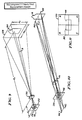
- Fig. 1 illustrates in perspective form a portion of the inventive weapon training simulator of the invention.
- the simulator is principally comprised of a weapon 14 connected to a recoil simulator 62 mounted in housing 80.
- the recoil simulator is as described in U. S. Pat. No. 4,079,527 of Linton, et al, discussed above.
- Mounted on the weapon is a sensing system 2 with optical axis 8 aimed at an illumination source 10 on target 4.
- An additional illumination source 11 is provided for a purpose explained below.
- the sight line 6 of the trainee holding the weapon intersects optical axis 8 at the target 4.
- FIG. 2 An optical schematic of a preferred embodiment of the weapon mounted sensing system is shown in Fig. 2 where an objective lens 16 having an optical axis 8 forms an image of the target mounted illumination source 10, near the plane of a quadrature detector array 20. Because array 20 is disposed in front of the image plane 18 of lens 16, the image 22 of source 10 is blurred on array 20. Array 20 is shown in enlarged detail in Fig. 3. It is a special feature of the invention that objective lens 16 either be square as shown or have a square aperture. It has been found that the square lens (or aperture) results in a more linear relationship between the signals from array 20 and angular deviation of source 10 from optical axis 8.
- FIG. 9 Another technique for achieving linear outputs from a quadrature detector array 20 is illustrated in the optical schematic diagram of Fig. 9.
- the target illumination source 28 completely defines the angular resolution of the target area on the detector array 20.
- Target illumination source 28 is shown as square having a vertical dimension of Dv and a horizontal dimension of Dh and is uniformly diffuse.
- the silhouette target 30 is transparent to the radiation from source 28.
- optical axis 3 of lens 32 is centered on the target 30 and illumination source 28 with the image 29 of source 28 centered on detector array 20. Because the source 28 is controlling the image 29, lens 32 can be either a conventional round objective or a square one as shown and described in connection with Fig. 2 and, the detector array 20 can be located in the image plane 18 simplifying optical alignment procedures.
- the image 29 of the source 28 on detector array 20 must be no more than one-half the size of the detector array. As can be seen from an inspection of Fig. 9, if the image were larger than one-half, displacing the center of the image less than one-quarter of the distance from the center of the array would result in signal fall-off as the source image falls off the edge of the array.
- a one inch square illumination source would produce full detector output for one-half inch displacement of the optical axis from the center of the target area.
- a two inch square source would produce full detector output for a one inch displacement.
- a uniform diffuse source 28 is both costly and difficult to achieve as well as distracting to some trainees, it is desirable that an alternate source be employed. It is a feature of the invention that the functional equivalent of such a source can be achieved by using the defocussed image of one or more point sources at the target to achieve this and other advantageous effects. Such an equivalent system is shown in Fig. 10.
- two point sources which advantageously may be light emitting diodes, are used in the optical system illustrated to achieve the equivalent of the two uniform diffuse sources.
- the objective lens with square aperture 16 focuses the image of point sources 40 and 44 at 42 and 46, respectively, in the image plane.
- quadrature detector array 20 being located in front of the image plane, has imaged on it the squared blurred images of the sources. The location of the detector array in the system is established so that the squared blurred images just touch at the center (on optical axis 8) to form a continous uniform intensity blurred image with a 2 to 1 width to height ratio.
- the ballistics of the weapon being simulated can be introduced into the sensor output data by appropriate arrangement of the point sources.
- weapon sight line 6 goes through the center of targets located both at ranges 72 and 74.
- the trajectory of the projectile is shown at 70 from the muzzle at the left in Fig. 4 to the right toward the target 72 or 74.
- the target mounted point source is mounted below the nominal center position of the target by the distance between 72 and 76 as measured on the target.
- Such an offset is shown in Fig. 1 where point source 11 is located below target center 10. This relocation of the point source compensates for projectile trajectory with no change in data processing being required.
- the target point source is then located at the center position 10 as shown in Fig. 1.
- the inventive system achieves compensation for weapon/projectile ballistics and target horizontal velocity.
- Tr time in seconds to target at range r (from Fig. 5)
- lead v x Tr x 39.37
- the point source For a target moving to the right, the point source would be displaced to the right, at the target, the simulated distance given by this formula. This will compensate for the required lead with no change in data processing.
- each point source is displaced the distance required for maximum target velocity v max, the relative amplitude of each source is described as follows where source brightness is equal to B at zero velocity:
- LED's light emitting diodes
- a visible light on or near the target proves distracting to either a trainee or experienced shooter.
- LED's are readily available emitting only in the infra-red spectrum and hence invisible to the human eye.
- the LED's are also capable of high speed pulsing at various power levels, features which are also necessary in the preferred practice of the invention.
- the digital aim point data from Aim Data Converter 52 can be modified by CPU and Memory 54 to include corrections for ballistics, target range, target velocity, round dispersion, rifle cant angle, and simulator parallax providing true hit point data.
- the first four corrections require only tables of weapon characteristics included in the software plus simulated target range and velocity.
- Rifle cant angle and simulator parallax corrections require additional sensing and will be described later.
- the radiation source LED's carried by each target are pulsed in sequence.
- simple timing gates in the CPU and Memory 54 identify the target source generating aim point data.
- the display elements are represented in Fig. 8 as the Video Controller 55 and Monitor 58.
- a target assembly which provides simulated targets at various ranges and positions is also required.
- the target assembly 61 receives its commands and returns target information through the I/O device 56.
- Speech and Tone Generator 60 provides this capability.
- the Recoil Assembly as shown in Fig. 1 is controlled by inputs from I/O device 56 and Recoil Driver 65. Amplitude and duration of the recoil impulse are controlled. The impulse is initiated by Hammer Fall Sensor 63 located in the simulated weapon 14. This impulse can start when the hammer falls or it can be delayed to provide additional training and diagnostic information.
- Printer 68 can provide a permanent record of anything that appears on video monitor 58. It also provides permanent records of charts showing the overall results of any program.
- the FIFO memory data is transferred to the memory location associated with the shot number.
- aim point and/or hit point can be replayed. They can be replayed individu simplyally or simultaneously.
- Sensing, measuring and displaying of rifle cant angle is a feature of the inventive system and utilizes two point illumination sources at the target as shown in Fig. 1 to effect cant angle measurement.
- the primary target illumination source is located at 10 while the second source 11 is located several milliradians away from the primary illumination source and, as shown, the second source is vertically displaced. It could also be horizontally displaced and still function for cant angle measurement. However, for ease of computation, the second radiation source should be located either directly above or below primary source 10 or directly to the right or left.
- the primary 10 and secondary 11 point sources are pulsed alternately to enable their identification and enhance signal strength.
- Fig. 7 illustrates the effect and measurement of cant angle.
- the Signt Line-Bore Angle is designated SB and is defined as the angle between the rifle sight line 6 and the bore line 73. It is because this angle exists that errors in the projectile hit point occur when the rifle is canted.
- SB is approximately 0.002 radians.
- CA cant angles
- cant angle reaches 75° as it frequently can do when the shooter fires while wearing a gas mask, the error becomes significant.
- the distance from sensor 2 to target 4 is 100 inches, obviously much less than the hundreds of meters encountered on the range or in the field.
- the rifle To provide a reasonable freedom of motion for the shooter, the rifle must be free to move toward and away from the target at least 5 inches.
- a typical distance between the sight line 6 and sensor axis 8 measured at the rifle, is 1 inch and the sight line 6 and sensor axis 8 coincide at the target at the nominal 100 inch actual range (that may be used to simulate a range of hundreds of meters).
- These dimensions give a parallax angle therebetween of 0.010 radians. At an actual range of 95 inches, the parallax angle is 0.0105 radians and at 105 inches is 0.0095 radians or a difference of 0.001 radians.
- a rotary angle sensor 82 is coupled to slack band drum 84 through shaft 86.
- Vertical or horizontal motion of rifle 14 does not cause carriage 90 to move but rifle motion toward or away from the target is transmitted to that carriage through recoil arm 94 and pull rod 88 as explained in the above referenced U. S. Patent No. 4,079,525 of Linton, et al.
- Motion of carriage 90 causes slack band drum 84 to rotate through action of recoil band 96 and slack band 92. This results in rotation of shaft 86 and a proportional output from rotary angle sensor 82 which is electrically coupled to the computer of the invention where that output is used in the computation and correction of Parallanix° as described further below.
- the training system of the invention provides a special purpose computer.
- the circuit diagram of that computer is shown in block diagram form in Fig. 8 with the system console control panel shown at Fig. 13.
- the amplified analog signals SA, SB, SC and SD at the output of detector array 20 of Fig. 3, are applied to the input of Aim Point Data Converter 52 of the Fig. 8 computer system.
- the other inputs to the computer are received from hammer fall sensor 63 which is contained in weapon 14 and rotary angle sensor 82 located in the recoil simulator 62.
- the remaining inputs are commands generated by the control panel of Fig. 13 which is connected (not shown) to I/O (input-output) device 56. These commands instruct the CPU (central processing unit) and Memory which of several internally stored software programs is to be used in execution of a required algorithm.
- the four output signals of the detector array 20 are combined by converter 52 to generate the analog vertical and horizontal aim point deviation signals Sv and Sh, respectively.
- two point illumination sources are employed in determination of Cant Angle and these sources are pulsed alternately to enable their identification.
- the alternate pulsing is under the direction and control of CPU and Memory 54.
- similar data is determined for the second sensor and then, these data are compared in CPU and Memory 54 to provide ⁇ V and ⁇ H values which, in turn, are used in computing Cant Angle under the formula described above.
- Rotary angle sensor 82 continuously transmits rifle position Parallanix° data to CPU and Memory 54 through I/O device 56.
- CPU and Memory 54 computes the required X and Y aim point correction and adds it to the aim point data corrected for Cant Angle in CPU and Memory 54.
- This true aim point data is then continuously stored in Aim Point FIFO memory.
- Weapon ballistics, weapon Cant Angle and Target characteristics are then introduced from memory and computed corrections are added to the true Aim Point data in CPU and Memory 54 and this data is continuously stored in the Hit Point FIFO memory.
- the control panel 100 of Fig. 13 provides the means for entering command control signals for the weapon training simulator system.
- the simulator system incorporates software programs at varous skill levels to substitute for instructor provided training or to assist in instructor guided training.
- the programs have been created to provide instruction in all 3 of the basic skills of holding, aiming and firing with appropriate voice and/or visual feedback to achieve the equivalent of the various training methods used in range training as described above.
- shot noise instructor commands including real time feedback on trainee performance, video displays and printouts that are the equivalent of the target box and dime/washer exercises as well as many others described below.
- Each of these programs and levels are produced upon commands entered on control panel 100 as follows.
- Power switch 102 energizes the system.
- Program button switch 104 is used to select a numbered program which is indicated on digital readout 106. Each depression of button 104 advances the program until the end of the sequence of stored programs when it repeats beginning at the lowest numbered program.
- Each depression of level button switch 108 advances the program level one increment. In general for rifle training the program levels have been established for stationary, walking, jogging and running targets; the selected level being displayed on digital readout 110. Each of the selected programs at each of the selected program levels provides for solution of the basic aiming equations with appropriate corrections for weapon and projectile ballistics at the selected ranges, cant angle, Parallanix°, and lead angle for moving targets along with visual and audio feedbacks as commented on further below.
- Start button switch 112 starts the selected program and program level from its beginning and clears all scoring and shot data from memory.
- Clear button switch is used to clear all scoring and shot data from memory without reinitiating a program start.
- the pause button switch 116 when pressed once suspends any program exercise in progress while a second depression causes the program to resume.
- the system console provides a video monitor 58 and a printer 68 for visual feedback to the trainee and instructor.
- Tapping the replay button causes the hit location of the last shot to be displayed. Tapping it twice, results in the display of the second to last shot, etc., for up to 64 shots. Holding the replay button down causes a replay of displayed shot to appear, i.e., the movement of the aiming point for the 5 seconds immediately prior to the time of the shot.
- Target button switch 120 selects one of the targets or a scoring table for display on the video monitor 58.
- targets move at more than one speed and in more than one direction.
- Motion button switch 122 selects each of these target conditions that occurred in the program in sequence, and highlights the hit locations for each of the shots fired in that condition.
- the print button switch 124 energizes printer 68 which prints and ejects a copy of the score chart or target that is displayed on the video monitor.
- Rifle recoil selector switch 126 sets the recoil force generated by recoil driver 65 and which is transmitted to the training rifle 14 by recoil assembly 62, anywhere from zero to 140% of that of the M16A1 rifle.
- misfire button switch 128 causes the rifle to apparently misfire; i.e., there is no recoil or sound but all other functions such as the video aiming trace and scoring remain normal.
- the sound selector switch 120 sets the shot sound in headphones worn by the trainee shooter anywhere between zero to 135 db.
- the circuitry of Fig. 8 comprises a Central processor unit and Memory 54 which stores a plurality of software programs in read only memory (ROM) and also provides random access memory (RAM) for storage of hit and intermediate algorithm computation results. While particular currently available microcomputer and memory technologies have been employed in the circuitry of Fig. 8, all or part of these functions may be contained within a single monolithic integrated circuit. It follows that the invention presented herein can take full advantage of present and future microelectronic evolutions to perform the functions required of the basic concept.
- Aim Tone can be better envisaged by referring to Fig. 12.
- a tone is generated by tone generator 60 anytime the hit or aim point falls within central hit area 17 of target 4.
- computer generated speech from generator 60 tells the trainee to move right, left, up or down anytime the hit point is not within area 17. In this manner, the trainee shooter is directed to a proper aim point without instructor intervention.
- a particular tone is generated if the hit point is off the target.
- speech generator 60 tells the trainee the hit point was high, low, left or right.
- a different tone is generated to indicate the hit point was inside target area 17. The trainee shooter can be required to shoot more accurately by indicating a miss if the hit point is outside of hit area 13.
- Trainer talk has many additional functions. It is used to tell the trainee to look at the video monitor 58 when the simulator system determines in accord with predetermined criteria that a shooting error should be displayed. It provides commands similar to range commands when a training program is in progress informing the trainee of target range and/or speed and/or position when this is appropriate. It tells the shooter the score of each shot when he is shooting at a target with scoring rings. When appropriate, it tells the shooter what functions to initiate by control panel entry; whether he must shoot fast, slow, track, trap, point, multiple shot, all based on the particular training program in progress and/or the manner the shooter is performing as measured by the simulator system.
- Another method of providing delayed recoil involves software in CPU and Memory 54 and allows for a special Delayed Recoil Replay.
- the aim point data and hit point data are flagged with a hammer fall code before being stored in the Replay FIFO.
- the hammer fall data is then delayed by the time ordered by the softwear.
- Aim Point and Hit Point data continue to flow into the Replay FIFO memories during the delay.
- the recoil pulse data is sent to Recoil Driver 65 through I/O device 56.
- the Aim Point data and Hit Point data are flagged with a recoil pulse code and sent to the Replay FIFO memories indicating the end of the Replay for that shot.
- the Replay FIFO memories are immediately dumped into the Replay memory associated with the shot member and Replay Data storage for the next shot continues in the FIFO memories.
- the interval that all of the above data is being stored for replay it is being displayed on the video monitor so the instructor can observe the trainee shooters aiming and firing techniques directly. The instructor can often critique the trainee shooter without using the Replay function.
- Replay data storage is the same as described above except the recoil data pulse is sent to Recoil Driver 65 from CPU and Memory 54 without delay and the Aim point data and Hit point data are immediately flagged with a recoil pulse and sent to the FIFO memories indicating the end of replay for that shot and the Replay FIFO memories are immediately dumped.
- Multiple-Hit Kill is a special Kill mode.
- the normal Kill Mode When the normal Kill Mode is active in the inventive weapon simulator, the target is dropped from sight after proper delay when a Hit is sensed by CPU and Memory 54. With Multiple-Hit Kill, two or more hits in rapid succession are required before the target drops from sight. This mode is used to teach the shooter how to recover from recoil and reacquire his sight picture to fire more than one accurate shot in rapid sequence at a target that is difficult to hit.
- Disperz refers to the modification of Hit Point data to include the actual ammunition dispersion data. This data is added statistically to the computed Hit Point in CPU and Memory 54 to provide a realistic simulation of the actual ammunition dispersion in the Final Hit Point. For analysis of each shot, a circle the size of the dispersion, centered on the non-dispersed Hit Point, is displayed on the video monitor for each shot and the randomly selected statistical Hit Point somewhere inside the circle, is displayed as the Hit Point for each shot.
- Show Cant is the display of weapon Cant Angle on the Video Monitor 58 while the shooter is engaging a target as well as a display during Replay.
- Cant is the audio instruction from Trainer Talk to the trainee shooter telling him that weapon Cant Angle is excessive for the range situation being simulated.
- Aim Point Replay utilizes the real time sensing, storage and recall capabilities of the inventive weapon simulator system to display on the Video monitor 58 in real time a replay of the Aim Point of a simulated weapon relative to a target for several seconds prior to firing the weapon.
- the data initially stored in the Aim Point FIFO memory and then dumped to Replay Memory is the real time data source.
- Aim Point Show is the continuous video display of aim point while the trainee shooter is acquiring the target and aiming the weapon in preparation for firing.
- the display can be either a bright spot or a simulated sight picture. The instructor can use this display directly for correcting shooter problems without using Replay.
- Delayed Recoil Replay provides a real time replay of the Hit Point of the simulated weapon 14 when the Delayed Recoil Function is initiated in the inventive weapon simulator.
- both the instant of hammer fall and the instant of recoil are flagged in the Hit Point Replay memory data.
- this stored real time data is displayed on the monitor both the Hit Point at hammer fall and at recoil are identified so Hit Point motion and thus weapon motion before and after trigger pull can be observed and analyzed to determine the trigger jerk, recoil anticipation and follow-through of the trainee.
- Delayed Recoil Replay and Hit Point Replay are always displayed with the target stationary on the Video monitor even for a moving target. This provides a high resolution display for detailed analysis of problems at the time of trigger pull.
- Simulreplay is the simultaneous real time display of both the Aim Point Replay memory data and the Hit Point Replay memory data.
- the Aim Point is displayed small scale to allow for display of the movement of a moving target through terrain across the sector of fire.
- Hit Point is displayed large scale on a stationary target to allow detailed analysis.
- the display of Hit Point on the video monitor is delayed after the weapon is fired.
- the trainee shooter moves a cursor on the blank target display to the position he thinks his shot hit the target.
- the trainee shooter, or the instructor then activates the "Call It” shot recording which stores the called shot position.
- the video monitor displays the shot and the called shot with the shot identified by shot number in a circle and the called shot identified by shot number in a square. All shots and called shots at the target can be displayed if desired. Also, when the target is printed out for a permanent record the shots and called shots are similarly identified.
Landscapes
- Engineering & Computer Science (AREA)
- Radar, Positioning & Navigation (AREA)
- General Engineering & Computer Science (AREA)
- Aiming, Guidance, Guns With A Light Source, Armor, Camouflage, And Targets (AREA)
Priority Applications (1)
| Application Number | Priority Date | Filing Date | Title |
|---|---|---|---|
| DE1989619824 DE68919824T2 (de) | 1989-01-31 | 1989-01-31 | Waffenschiesssimulatorsystem. |
Applications Claiming Priority (1)
| Application Number | Priority Date | Filing Date | Title |
|---|---|---|---|
| US06/863,465 US4804325A (en) | 1986-05-15 | 1986-05-15 | Weapon training simulator system |
Publications (2)
| Publication Number | Publication Date |
|---|---|
| EP0380724A1 true EP0380724A1 (de) | 1990-08-08 |
| EP0380724B1 EP0380724B1 (de) | 1994-12-07 |
Family
ID=25341147
Family Applications (1)
| Application Number | Title | Priority Date | Filing Date |
|---|---|---|---|
| EP89101647A Expired - Lifetime EP0380724B1 (de) | 1986-05-15 | 1989-01-31 | Waffenschiesssimulatorsystem |
Country Status (2)
| Country | Link |
|---|---|
| US (1) | US4804325A (de) |
| EP (1) | EP0380724B1 (de) |
Cited By (2)
| Publication number | Priority date | Publication date | Assignee | Title |
|---|---|---|---|---|
| WO1993003322A1 (en) * | 1991-08-07 | 1993-02-18 | Viljo Lukkarinen | A method and device to practice shooting |
| FR2833692A1 (fr) | 2001-12-17 | 2003-06-20 | Jean Noel Bruere | Simulateur de recul a volant d'inertie |
Families Citing this family (45)
| Publication number | Priority date | Publication date | Assignee | Title |
|---|---|---|---|---|
| US4955812A (en) * | 1988-08-04 | 1990-09-11 | Hill Banford R | Video target training apparatus for marksmen, and method |
| US4923402A (en) * | 1988-11-25 | 1990-05-08 | The United States Of America As Represented By The Secretary Of The Navy | Marksmanship expert trainer |
| US5194006A (en) * | 1991-05-15 | 1993-03-16 | Zaenglein Jr William | Shooting simulating process and training device |
| US5194008A (en) * | 1992-03-26 | 1993-03-16 | Spartanics, Ltd. | Subliminal image modulation projection and detection system and method |
| US5823779A (en) * | 1996-05-02 | 1998-10-20 | Advanced Interactive Systems, Inc. | Electronically controlled weapons range with return fire |
| US5947738A (en) * | 1996-08-26 | 1999-09-07 | Advanced Interactive Systems, Inc. | Simulated weapon with gas cartridge |
| EP1007896B1 (de) * | 1997-08-25 | 2004-12-29 | Beamhit L.L.C. | Mit einem laser funktionierende übungswaffe welche mit einem netzwerk verbunden ist |
| US20040014010A1 (en) * | 1997-08-25 | 2004-01-22 | Swensen Frederick B. | Archery laser training system and method of simulating weapon operation |
| AU2818099A (en) * | 1998-03-13 | 1999-10-11 | Karl Stefan Riener | Receiving unit, device and system for determining the position or movement of a weapon, and a method therefor |
| US6604064B1 (en) * | 1999-11-29 | 2003-08-05 | The United States Of America As Represented By The Secretary Of The Navy | Moving weapons platform simulation system and training method |
| AU2001237945A1 (en) * | 2000-01-13 | 2001-07-24 | Beamhit, L.L.C. | Firearm laser training system and method employing modified blank cartridges forsimulating operation of a firearm |
| US6579098B2 (en) | 2000-01-13 | 2003-06-17 | Beamhit, Llc | Laser transmitter assembly configured for placement within a firing chamber and method of simulating firearm operation |
| US6575753B2 (en) | 2000-05-19 | 2003-06-10 | Beamhit, Llc | Firearm laser training system and method employing an actuable target assembly |
| US6616452B2 (en) | 2000-06-09 | 2003-09-09 | Beamhit, Llc | Firearm laser training system and method facilitating firearm training with various targets and visual feedback of simulated projectile impact locations |
| WO2002101318A2 (en) * | 2001-06-08 | 2002-12-19 | Beamhit, Llc | Firearm laser training system and method facilitating firearm training for extended range targets with feedback of firearm control |
| US20050153262A1 (en) * | 2003-11-26 | 2005-07-14 | Kendir O. T. | Firearm laser training system and method employing various targets to simulate training scenarios |
| EP1632744B1 (de) * | 2004-09-07 | 2014-08-20 | Saab Ab | Simulationssystem |
| KR100689486B1 (ko) * | 2004-10-18 | 2007-03-02 | 삼성전자주식회사 | 공명 공간을 이용하는 폴더형 휴대 단말기의 스피커 장치 |
| US20070152157A1 (en) * | 2005-11-04 | 2007-07-05 | Raydon Corporation | Simulation arena entity tracking system |
| US20070190495A1 (en) * | 2005-12-22 | 2007-08-16 | Kendir O T | Sensing device for firearm laser training system and method of simulating firearm operation with various training scenarios |
| US20070238073A1 (en) * | 2006-04-05 | 2007-10-11 | The United States Of America As Represented By The Secretary Of The Navy | Projectile targeting analysis |
| US9011151B1 (en) * | 2006-11-22 | 2015-04-21 | Raytheon Company | System and method for simulating firing a gun |
| US8613619B1 (en) | 2006-12-05 | 2013-12-24 | Bryan S. Couet | Hunter training system |
| US20100275491A1 (en) * | 2007-03-06 | 2010-11-04 | Edward J Leiter | Blank firing barrels for semiautomatic pistols and method of repetitive blank fire |
| US20080306708A1 (en) * | 2007-06-05 | 2008-12-11 | Raydon Corporation | System and method for orientation and location calibration for image sensors |
| US8827706B2 (en) * | 2008-03-25 | 2014-09-09 | Practical Air Rifle Training Systems, LLC | Devices, systems and methods for firearms training, simulation and operations |
| US8690575B1 (en) | 2008-11-03 | 2014-04-08 | ACME Worldwide Enterprises, Inc. | Apparatus and method for a weapon simulator |
| US8215165B2 (en) * | 2009-04-27 | 2012-07-10 | Ultimate Ballistics Box, Llc | Torso simulator for ballistics testing |
| US8500016B2 (en) | 2011-05-24 | 2013-08-06 | Brian Finamore | Rifle sight analog template |
| US10260845B2 (en) | 2011-08-05 | 2019-04-16 | Board Of Regents Of The University Of Texas System | Marksmanship training aid |
| KR101179074B1 (ko) * | 2011-12-13 | 2012-09-05 | 국방과학연구소 | 공중폭발 모의시스템 및 공중폭발 모의방법 |
| US10852093B2 (en) | 2012-05-22 | 2020-12-01 | Haptech, Inc. | Methods and apparatuses for haptic systems |
| US9146069B2 (en) | 2012-05-22 | 2015-09-29 | Haptech, Inc. | Method and apparatus for firearm recoil simulation |
| US9182189B2 (en) | 2013-01-05 | 2015-11-10 | Stanley Hahn Seigler | Dry fire practice training device |
| US20150253109A1 (en) * | 2013-01-10 | 2015-09-10 | Brian Donald Wichner | Methods and Systems for Determining a Gunshot Sequence or Recoil Dynamics of a Gunshot for a Firearm |
| USD723129S1 (en) * | 2013-04-15 | 2015-02-24 | Henry Joseph Santistevan | Single shot loading tool |
| USD711493S1 (en) * | 2013-05-02 | 2014-08-19 | Charles H. Scull | Pistol recoil simulator |
| SG11201607730VA (en) | 2014-03-17 | 2016-10-28 | Meggitt Training Systems Inc | Systems and methods for automated coaching of a shooter |
| US9557405B2 (en) * | 2014-08-12 | 2017-01-31 | Bae Systems Information And Electronic Systems Integration Inc. | Tracking projectile trajectory with multiple sensors |
| US9746273B2 (en) * | 2014-11-14 | 2017-08-29 | Pathfinder Systems, Inc. | Recoil simulator and method for an imitation machine gun |
| USD766396S1 (en) * | 2016-05-28 | 2016-09-13 | Charles H. Scull | Automatic pistol recoil simulator |
| US10648781B1 (en) * | 2017-02-02 | 2020-05-12 | Arthur J. Behiel | Systems and methods for automatically scoring shooting sports |
| US12078454B2 (en) * | 2019-08-14 | 2024-09-03 | Cubic Defense Applications, Inc. | Universal laserless training architecture |
| US11703297B2 (en) | 2020-02-24 | 2023-07-18 | Stanley Hahn Seigler | Dry fire practice training device with bolt carrier group for rifles |
| CA3245640A1 (en) | 2022-03-11 | 2023-09-28 | Sarah R. Seigler | DRY-FIRING TRAINING DEVICE WITH SINGLE-BOLT PISTOLS |
Citations (7)
| Publication number | Priority date | Publication date | Assignee | Title |
|---|---|---|---|---|
| US3780300A (en) * | 1972-01-12 | 1973-12-18 | Aai Corp | Radiation sensitive hit detection arrangement |
| FR2321105A1 (fr) * | 1975-07-10 | 1977-03-11 | Australasian Training Aids Pty | Dispositif d'instruction pour un equipement sportif |
| US4065860A (en) * | 1975-09-22 | 1978-01-03 | Spartanics, Ltd. | Weapon training simulator |
| DE2823656A1 (de) * | 1978-05-30 | 1980-02-21 | Precitronic | Anzeigevorrichtung zur darstellung von messergebnissen o.dgl., sowie mit der anzeigevorrichtung ausgeruesteter schussimulator |
| DE2940513A1 (de) * | 1979-10-05 | 1981-04-16 | Heins AG, Glarus | Sicherheitsvorrichtung in einer schiessanlage |
| EP0160123A2 (de) * | 1983-11-17 | 1985-11-06 | Motoi Kuroiwa | Schussüberwachungsgerät |
| EP0285586A2 (de) * | 1987-03-25 | 1988-10-05 | Combinova Ab | Elektronisches Aufnahmegerät für die Treffgenauigkeit |
Family Cites Families (12)
| Publication number | Priority date | Publication date | Assignee | Title |
|---|---|---|---|---|
| US2023497A (en) * | 1932-06-11 | 1935-12-10 | Trammell Webb | Device for training and instruction in the firing of small arms |
| US2398813A (en) * | 1943-09-23 | 1946-04-23 | Edison General Elec Appliance | Gun-training apparatus |
| US3704530A (en) * | 1971-06-14 | 1972-12-05 | Gary N Arenson | Anti-flinch training apparatus |
| US3781547A (en) * | 1972-11-22 | 1973-12-25 | Us Air Force | Optical receiver with extended source discrimination |
| SE407976B (sv) * | 1973-03-13 | 1979-04-30 | Bofors Ab | Forfarande och anordning for malfoljning |
| GB1486188A (en) * | 1973-11-23 | 1977-09-21 | Emi Ltd | Tracking and/or guidance systems |
| US3992099A (en) * | 1973-12-12 | 1976-11-16 | Varo, Inc. | Source discriminator for measuring angle of arrival and wavelength of radiant energy |
| US4021007A (en) * | 1974-10-11 | 1977-05-03 | Northrop Corporation | Pitch-yaw stabilization system |
| US4079525A (en) * | 1976-06-11 | 1978-03-21 | Spartanics, Ltd. | Weapon recoil simulator |
| US4137651A (en) * | 1976-09-30 | 1979-02-06 | The United States Of America As Represented By The Secretary Of The Army | Moving target practice firing simulator |
| US4050166A (en) * | 1976-09-30 | 1977-09-27 | The United States Of America As Represented By The Secretary Of The Navy | Recoil simulator |
| US4504232A (en) * | 1983-03-03 | 1985-03-12 | The United States Of America As Represented By The Secretary Of The Navy | Battlefield friend or foe indentification trainer |
-
1986
- 1986-05-15 US US06/863,465 patent/US4804325A/en not_active Expired - Lifetime
-
1989
- 1989-01-31 EP EP89101647A patent/EP0380724B1/de not_active Expired - Lifetime
Patent Citations (7)
| Publication number | Priority date | Publication date | Assignee | Title |
|---|---|---|---|---|
| US3780300A (en) * | 1972-01-12 | 1973-12-18 | Aai Corp | Radiation sensitive hit detection arrangement |
| FR2321105A1 (fr) * | 1975-07-10 | 1977-03-11 | Australasian Training Aids Pty | Dispositif d'instruction pour un equipement sportif |
| US4065860A (en) * | 1975-09-22 | 1978-01-03 | Spartanics, Ltd. | Weapon training simulator |
| DE2823656A1 (de) * | 1978-05-30 | 1980-02-21 | Precitronic | Anzeigevorrichtung zur darstellung von messergebnissen o.dgl., sowie mit der anzeigevorrichtung ausgeruesteter schussimulator |
| DE2940513A1 (de) * | 1979-10-05 | 1981-04-16 | Heins AG, Glarus | Sicherheitsvorrichtung in einer schiessanlage |
| EP0160123A2 (de) * | 1983-11-17 | 1985-11-06 | Motoi Kuroiwa | Schussüberwachungsgerät |
| EP0285586A2 (de) * | 1987-03-25 | 1988-10-05 | Combinova Ab | Elektronisches Aufnahmegerät für die Treffgenauigkeit |
Cited By (2)
| Publication number | Priority date | Publication date | Assignee | Title |
|---|---|---|---|---|
| WO1993003322A1 (en) * | 1991-08-07 | 1993-02-18 | Viljo Lukkarinen | A method and device to practice shooting |
| FR2833692A1 (fr) | 2001-12-17 | 2003-06-20 | Jean Noel Bruere | Simulateur de recul a volant d'inertie |
Also Published As
| Publication number | Publication date |
|---|---|
| US4804325A (en) | 1989-02-14 |
| EP0380724B1 (de) | 1994-12-07 |
Similar Documents
| Publication | Publication Date | Title |
|---|---|---|
| EP0380724B1 (de) | Waffenschiesssimulatorsystem | |
| US4583950A (en) | Light pen marksmanship trainer | |
| US4619616A (en) | Weapon aim-training apparatus | |
| US4955812A (en) | Video target training apparatus for marksmen, and method | |
| US5026158A (en) | Apparatus and method for displaying and storing impact points of firearm projectiles on a sight field of view | |
| US4923402A (en) | Marksmanship expert trainer | |
| US5641288A (en) | Shooting simulating process and training device using a virtual reality display screen | |
| US4290757A (en) | Burst on target simulation device for training with rockets | |
| US5281142A (en) | Shooting simulating process and training device | |
| EP1007896B1 (de) | Mit einem laser funktionierende übungswaffe welche mit einem netzwerk verbunden ist | |
| US6616452B2 (en) | Firearm laser training system and method facilitating firearm training with various targets and visual feedback of simulated projectile impact locations | |
| US4439156A (en) | Anti-armor weapons trainer | |
| US6942486B2 (en) | Training simulator for sharp shooting | |
| US20070190495A1 (en) | Sensing device for firearm laser training system and method of simulating firearm operation with various training scenarios | |
| US20020197584A1 (en) | Firearm laser training system and method facilitating firearm training for extended range targets with feedback of firearm control | |
| US20040014010A1 (en) | Archery laser training system and method of simulating weapon operation | |
| WO1997041402B1 (en) | Electronically controlled weapons range with return fire | |
| SE506468C2 (sv) | Träfflägesmarkerare för hagelgevärsskytte | |
| US4302191A (en) | Aiming and gunnery training apparatus | |
| US5035622A (en) | Machine gun and minor caliber weapons trainer | |
| GB2030683A (en) | Gunnery training system | |
| US4923401A (en) | Long range light pen | |
| US3243896A (en) | Laser weapon simulator | |
| US20070254266A1 (en) | Marksmanship training device | |
| US2968877A (en) | Marksmanship trainer and recorder |
Legal Events
| Date | Code | Title | Description |
|---|---|---|---|
| PUAI | Public reference made under article 153(3) epc to a published international application that has entered the european phase |
Free format text: ORIGINAL CODE: 0009012 |
|
| AK | Designated contracting states |
Kind code of ref document: A1 Designated state(s): BE DE FR GB IT LU NL SE |
|
| 17P | Request for examination filed |
Effective date: 19901224 |
|
| 17Q | First examination report despatched |
Effective date: 19920709 |
|
| GRAA | (expected) grant |
Free format text: ORIGINAL CODE: 0009210 |
|
| ITF | It: translation for a ep patent filed | ||
| AK | Designated contracting states |
Kind code of ref document: B1 Designated state(s): BE DE FR GB IT LU NL SE |
|
| ET | Fr: translation filed | ||
| REF | Corresponds to: |
Ref document number: 68919824 Country of ref document: DE Date of ref document: 19950119 |
|
| EAL | Se: european patent in force in sweden |
Ref document number: 89101647.9 |
|
| PLBE | No opposition filed within time limit |
Free format text: ORIGINAL CODE: 0009261 |
|
| STAA | Information on the status of an ep patent application or granted ep patent |
Free format text: STATUS: NO OPPOSITION FILED WITHIN TIME LIMIT |
|
| 26N | No opposition filed | ||
| PGFP | Annual fee paid to national office [announced via postgrant information from national office to epo] |
Ref country code: FR Payment date: 19961209 Year of fee payment: 9 |
|
| PGFP | Annual fee paid to national office [announced via postgrant information from national office to epo] |
Ref country code: SE Payment date: 19961217 Year of fee payment: 9 |
|
| PGFP | Annual fee paid to national office [announced via postgrant information from national office to epo] |
Ref country code: DE Payment date: 19961218 Year of fee payment: 9 |
|
| PGFP | Annual fee paid to national office [announced via postgrant information from national office to epo] |
Ref country code: GB Payment date: 19961219 Year of fee payment: 9 Ref country code: BE Payment date: 19961219 Year of fee payment: 9 |
|
| PGFP | Annual fee paid to national office [announced via postgrant information from national office to epo] |
Ref country code: NL Payment date: 19961223 Year of fee payment: 9 |
|
| PGFP | Annual fee paid to national office [announced via postgrant information from national office to epo] |
Ref country code: LU Payment date: 19970408 Year of fee payment: 9 |
|
| PG25 | Lapsed in a contracting state [announced via postgrant information from national office to epo] |
Ref country code: LU Free format text: LAPSE BECAUSE OF NON-PAYMENT OF DUE FEES Effective date: 19980131 Ref country code: GB Free format text: LAPSE BECAUSE OF NON-PAYMENT OF DUE FEES Effective date: 19980131 Ref country code: FR Free format text: THE PATENT HAS BEEN ANNULLED BY A DECISION OF A NATIONAL AUTHORITY Effective date: 19980131 Ref country code: BE Free format text: LAPSE BECAUSE OF NON-PAYMENT OF DUE FEES Effective date: 19980131 |
|
| PG25 | Lapsed in a contracting state [announced via postgrant information from national office to epo] |
Ref country code: SE Free format text: LAPSE BECAUSE OF NON-PAYMENT OF DUE FEES Effective date: 19980201 |
|
| BERE | Be: lapsed |
Owner name: SPARTANICS LTD Effective date: 19980131 |
|
| PG25 | Lapsed in a contracting state [announced via postgrant information from national office to epo] |
Ref country code: NL Free format text: LAPSE BECAUSE OF NON-PAYMENT OF DUE FEES Effective date: 19980801 |
|
| GBPC | Gb: european patent ceased through non-payment of renewal fee |
Effective date: 19980131 |
|
| NLV4 | Nl: lapsed or anulled due to non-payment of the annual fee |
Effective date: 19980801 |
|
| PG25 | Lapsed in a contracting state [announced via postgrant information from national office to epo] |
Ref country code: DE Free format text: LAPSE BECAUSE OF NON-PAYMENT OF DUE FEES Effective date: 19981001 |
|
| REG | Reference to a national code |
Ref country code: FR Ref legal event code: ST |
|
| EUG | Se: european patent has lapsed |
Ref document number: 89101647.9 |
|
| PG25 | Lapsed in a contracting state [announced via postgrant information from national office to epo] |
Ref country code: IT Free format text: LAPSE BECAUSE OF NON-PAYMENT OF DUE FEES;WARNING: LAPSES OF ITALIAN PATENTS WITH EFFECTIVE DATE BEFORE 2007 MAY HAVE OCCURRED AT ANY TIME BEFORE 2007. THE CORRECT EFFECTIVE DATE MAY BE DIFFERENT FROM THE ONE RECORDED. Effective date: 20050131 |