EP0380802A1 - Aufzugssystem mit unabhängiger Beschränkung des Geschwindigkeitssollwertes in den Endzonen - Google Patents
Aufzugssystem mit unabhängiger Beschränkung des Geschwindigkeitssollwertes in den Endzonen Download PDFInfo
- Publication number
- EP0380802A1 EP0380802A1 EP89123415A EP89123415A EP0380802A1 EP 0380802 A1 EP0380802 A1 EP 0380802A1 EP 89123415 A EP89123415 A EP 89123415A EP 89123415 A EP89123415 A EP 89123415A EP 0380802 A1 EP0380802 A1 EP 0380802A1
- Authority
- EP
- European Patent Office
- Prior art keywords
- car
- terminal
- zone
- speed
- elevator car
- Prior art date
- Legal status (The legal status is an assumption and is not a legal conclusion. Google has not performed a legal analysis and makes no representation as to the accuracy of the status listed.)
- Granted
Links
- 238000013459 approach Methods 0.000 claims abstract description 4
- 230000004044 response Effects 0.000 claims abstract description 4
- 230000010354 integration Effects 0.000 abstract description 2
- 230000006870 function Effects 0.000 description 24
- 238000010586 diagram Methods 0.000 description 5
- 230000009977 dual effect Effects 0.000 description 5
- 239000000872 buffer Substances 0.000 description 2
- 238000000034 method Methods 0.000 description 2
- 238000005070 sampling Methods 0.000 description 2
- 239000007787 solid Substances 0.000 description 2
- 230000007704 transition Effects 0.000 description 2
- 101150007667 FPS2 gene Proteins 0.000 description 1
- 230000036461 convulsion Effects 0.000 description 1
Images

Classifications
-
- B—PERFORMING OPERATIONS; TRANSPORTING
- B66—HOISTING; LIFTING; HAULING
- B66B—ELEVATORS; ESCALATORS OR MOVING WALKWAYS
- B66B5/00—Applications of checking, fault-correcting, or safety devices in elevators
- B66B5/02—Applications of checking, fault-correcting, or safety devices in elevators responsive to abnormal operating conditions
- B66B5/08—Applications of checking, fault-correcting, or safety devices in elevators responsive to abnormal operating conditions for preventing overwinding
- B66B5/10—Applications of checking, fault-correcting, or safety devices in elevators responsive to abnormal operating conditions for preventing overwinding electrical
-
- B—PERFORMING OPERATIONS; TRANSPORTING
- B66—HOISTING; LIFTING; HAULING
- B66B—ELEVATORS; ESCALATORS OR MOVING WALKWAYS
- B66B1/00—Control systems of elevators in general
- B66B1/24—Control systems with regulation, i.e. with retroactive action, for influencing travelling speed, acceleration, or deceleration
- B66B1/28—Control systems with regulation, i.e. with retroactive action, for influencing travelling speed, acceleration, or deceleration electrical
- B66B1/285—Control systems with regulation, i.e. with retroactive action, for influencing travelling speed, acceleration, or deceleration electrical with the use of a speed pattern generator
Definitions
- the invention relates in general to elevator systems, and more specifically to providing an independent control over terminal slowdown of an elevator car as it approaches a terminal floor of a building.
- An elevator system requires a normal terminal stopping arrangement for an elevator car which is independent of the normal slowdown and stopping arrangement for the car.
- the normal terminal stopping arrangement will automatically override the normal slowdown and stopping arrangement, reducing the speed of the car according to a predetermined deceleration schedule, to stop the car smoothly at the terminal floor.
- the normal terminal slowdown function will hereinafter be referred to as TSD, for "Terminal Slow Down".
- TSD Terminal Slow Down
- some additional emergency terminal device must be used. For example, with reduced stroke buffers, an emergency terminal speed limiting device must be used which is independent of any other emergency related device.
- ETS Emergency Terminal Stop
- the present invention is related to TSD, not ETS, and is thus related to apparatus for automatically overriding the normal slowdown and stopping control of an elevator car, when the normal slowdown control is malfunctioning, to smoothly stop the car at a terminal floor without exceeding predetermined values of deceleration and/or jerk.
- the present invention is a feedback controlled elevator system of the traction type in which the normal slowdown and stopping of an elevator car is controlled by a speed pattern SP.
- Independent TSD is provided according to the teachings of the invention by establishing a terminal slowdown zone in a hatch which defines the travel path of an elevator car, adjacent to the upper and lower terminal floors of the associated building, such as by mechanical or solid state switches.
- the associated switch provides a true signal, with a true signal TSDU indicating the car is in the upper TSD zone, and a true signal TSDL indicating the car is in the lower TSD zone.
- a positional datum using a similar switch is established within each TSD zone, such as 12 inches from the terminal floor, to accommodate those instances when the elevator system is initialized when the car is parked in a TSD zone.
- the positional datum switch provides a true signal TS12U
- the positional datum switch provides a true signal TS12L.
- the position of the elevator car in a TSD zone is determined by digital integration of first and second phase related digital signals P1 and P2 which are provided by a digital shaft encoder on the shaft of a traction drive motor which drives a traction sheave. Motion is imparted to the elevator car and a counterweight, which are interconnected via wire ropes, by reeving the wire ropes about the traction sheave.
- First and second binary counters are arranged such that when the car enters a TSD zone, the first counter will count pulses of the first signal P1 when the car is traveling in one direction, and the second counter will count pulses of the second signal P2 when the car is traveling in the opposite direction, i.e., each counter accumulates counts in only one direction of drive motor rotation, and this direction is different for the two counters.
- the output counts are sampled and subtracted to obtain a binary position value BPV for the motor shaft rotation, and this value is further processed to find the incremental position change IPC since the previous sample was taken.
- Signals TSDU and TSDL are sampled and respectively used to latch first and second flip flops when true, which accordingly provide true signals TSU and TSL when latched. According to which latch signal is true, each incremental position change is either added to or subtracted from a car position integral "x".
- the car position integral "x" is a digital value which represents the distance traveled by the elevator car into a TSD zone, and it is used to address a read-only memory (ROM) which has pre-calculated speed limit values stored therein for each digital value of "x".
- the normal speed pattern SP generated by a car controller is applied to a motor control servo via a limiter which selects the lesser of two magnitudes applied to it. One of the magnitudes is the normal speed pattern SP.
- the remaining input is controlled by an analog switch which selects the output of the speed limit memory when the car is in a TSD zone traveling toward the associated terminal floor, and which otherwise selects the contract speed CSL of the elevator car, ie., the normal maximum speed of the elevator car.
- the position of the car relative to the position datum controls the start-up procedure. If the car is not between the position datum and the terminal floor, the position integral "x" is jammed to a value which corresponds to the position of the position datum, i.e., 12 inches from the terminal floor, for example. This allows the elevator car to move at a safe speed towards the terminal floor, ie., the speed limit which would be applied when the car passes the position datum on its way to stopping at the terminal floor; or, car 12 may move away from the floor at any speed up to contract speed CSL. If the car moves towards the terminal floor, "x" will be released when the car reaches the positional datum, and normal operation will then continue from that point. If the car travels in the opposite direction, "x" is set to zero when the car leaves the TSD zone.
- the position integral "x" is jammed to a value which corresponds to a position close to the terminal floor, such as one inch. This allows the car to move towards the terminal floor at a very low speed, or away from the floor at any speed up to CSL.
- "x" will be set to the 12 inch position, and normal operation will then control the value of "x".
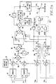
- an elevator system 10 in diagrammatic and block form constructed according to the teachings of the invention. Only a portion of an elevator system necessary to understand the invention is disclosed. For a more complete description of an elevator system, reference may be had to U.S. Patents 3,750,850; 4,161,235; and 4,416,352, all of which are assigned to the same assignee as the present application, and which are hereby incorporated into the specification of the present application by reference.
- Elevator system 10 includes an elevator car 12 mounted in a hatch or hoistway 14 for guided movement relative to a building 16 having a plurality of floors or landings. Only the upper and lower terminal floors, indicated by reference numerals 18 and 20, respectively, are shown in order to simplify the drawing. Elevator car 10 is supported by a plurality of wire ropes 22 which are reeved over a traction sheave 24 mounted on the shaft 26 of a traction drive machine 28.
- Drive machine 28 includes a drive motor 30, which may be an AC motor or a DC motor, as desired, drive motor control 32, and a shaft encoder 34.
- a counterweight 36 is connected to the other ends of ropes 22.
- Terminal slowdown apparatus 40 constructed according to the teachings of the invention utilizes six digital input signals.
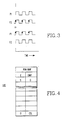
- the first two digital input signals are P1 and P2 provided by shaft encoder 34.
- P1 digital signal P1
- P2 leads signal P1 by 90 degrees.
- the third and fourth digital input signals are TSDU and TSDL which are indicated in Figure 1 as being provided by mechanical switches 42 and 44 mounted in hatch 14 which are actuated by a cam 46 carried by elevator car 12. Any other form of switch may be used, such as solid state.
- Switch 42 is located such that it will be actuated to provide a true signal TSDU as car 12 ascends and enters an upper TSD zone 43.
- Switch 42 will maintain the true TSDU signal until car 12 descends and leaves the upper TSD zone 43.
- switch 44 is located such that it will be actuated to provide a true signal TSDL as car 12 descends and enters a lower TSD zone 45.
- Switch 44 will maintain the true TSDL signal until car 12 ascends and leaves the lower TSD zone 45.
- the length "S" of a TSD zone in feet may be determined from the maximum or contract speed CSL of the elevator car in FPS and the desired rate of deceleration "A" in FPS2 according to the following formula:
- the remaining two digital signals TS12U and TS12L are provided by hatch mounted switches 48 and 50.
- Switch 48 is mounted to provide a positional datum in the upper TSD zone 43
- switch 50 is mounted to provide a similar positional datum in the lower TSD zone 45.
- the positional datum is related to the associated terminal floor, and the distance from the floor is selected such that the desired car speed at that point as car 12 lands at the terminal floor will be a safe initial speed to move the car towards the terminal floor when elevator system 10 is initialized within a TSD zone. For purposes of example, this distance is selected as 12 inches (30.48 cm).
- switch 48 establishes an upper 12 inch zone 52 adjacent the upper terminal floor 18, and switch 50 establishes a lower 12 inch zone adjacent the lower terminal floor 54.
- Switch 48 is located such that it will actuated by cam 46 to provide a true signal TS12U as car 12 ascends and enters the upper 12 inch zone 52. Switch 48 will maintain the true TS12U signal until car 12 descends and leaves the upper 12 inch zone 52.
- switch 50 is located such that it will actuated to provide a true signal TS12L as car 12 descends and enters the lower 12 inch zone 54. Switch 50 will maintain the true TS12L signal until car 12 ascends and leaves the lower 12 inch zone 54.
- TSD apparatus 40 includes a TSD limit function 56, a terminal zone detector function 58, a limiter function 60, a contract speed function 62, and a switch 64, such as an analog switch.
- a car controller 66 for car 12 may be the car controller shown in incorporated patent 3,750,850.
- the TSD limit function 56 is responsive to all six of the hereinbefore described digital input signals, and it provides a pattern limit signal PTL for each incremental position of car 12 while it is in a TSD zone 43 or 45. TSD limit function 56 also provides a true signal TSU during the time car 12 is in the upper TSD zone 43, and a true signal TSL during the time car 12 is in the lower terminal zone 45.
- the terminal zone detector function 58 is responsive to the signals TSU and TSL provided by TSD limit function 56, and also to the travel direction of car 12, as indicated by signals UPTR and DNTR provided by motor drive control 32.
- Motor drive control 32 obtains car direction signals from car controller 66. By obtaining travel direction from motor controller 32, TSD apparatus 40 maintains the required independence from car controller 66.
- Signal UPTR is true when car 12 is set for up travel and signal DNTR is true when car 12 is set for down travel.
- Terminal zone detector function 58 operates switch 64 when car 12 is in a terminal zone, and is set for travel towards the terminal floor associated with the terminal zone. Switch 64 is normally set to connect a fixed voltage CSL to limiter 60 having a magnitude indicative of the contract speed of elevator car 12.
- switch 64 is normally set to connect a fixed voltage CSL to limiter 60 having a magnitude indicative of the contract speed of elevator car 12.
- Limiter 60 receives a speed pattern SP from car controller 66, and either the contract speed limit CSL or the pattern limit PTL. Limiter selects the lower of the two signals applied thereto at any instant, such as the pattern limiter disclosed in the incorporated U.S. Patent 4,161,235. Limiter 60 applies the lesser of the two active signals applied thereto to the motor drive control 32, which controls motor 30 according to the pattern received from limiter 60.
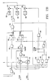
- FIG. 2 is a detailed schematic diagram of the TSD limit function and the terminal zone detector function 58, implemented according to preferred embodiments of the invention.
- the TSD system 40 is intended for implementation in a discrete data environment, such as a digital computer, where input data is sampled in the course of an algorithm which is executed at regular intervals of time.
- the digital sampling function is indicated generally at 65.
- a vertical array of switches 67 shown connected by a broken line 68 in Figure 2 functionally indicates the sampling of the binary input signals.
- the two binary signals P1 and P2 provided by shaft encoder 34 are used to clock two binary counters 70 and 72, respectively, in such a way that each counter counts in only one direction of motor shaft rotation, and this direction is different for the two counters.
- signal P1 leads signal P2 by 90 degrees.
- signal P1 may be used as an enable signal for counting positive going transitions of signal P2 on counter 72.
- signal P2 leads signal P1 by 90 degrees, and thus signal P2 may be used as an enable signal for counting positive going transitions of signal P1 on counter 70.
- the output counts of counters 70 and 72 are sampled and subtracted at a summing point 74 using the prescribed signs to obtain a binary position value BPV for motor shaft rotation.
- the new value of BPV is compared with the previous value provided by function block 76 at a summing point 78, using the prescribed signs, to determine the incremental position change IPC since the previous sample was taken.
- Input signals TSDU and TSDL are sampled and used to latch either of the two signals or flags TSU or TSL, with a true signal indicating the elevator car 12 is within the associated TSD zone, as hereinbefore described.
- Signals TSU and TSL are provided by dual input AND gates 80 and 82, each of which have one inverting input, and flip flops 84 and 86.
- Signals TSDU and TSDL are connected to the non-inverting inputs of AND gates 80 and 82, respectively, the outputs of AND gates 80 and 82 are connected to the set inputs S of flip flops 84 and 86, respectively, and the Q outputs of flip flops 84 and 86 are connected back to the inverting inputs of AND gates 82 and 80, respectively.
- a position integral "x" is either incremented by IPC, decremented by IPC, or not changed.
- the position integral "x" indicates the distance traveled by car 12 in a TSD zone, either zone 43 or zone 45.
- the car position integral "x" is used to address a look-up table 105 stored in a read-only memory 106.
- the look-up table 105 stored in memory 106 contains a car speed limit as an output signal for each input value of "x".
- the speed limit output PTL from memory 106 is applied to one input of switch 64.
- the other input to switch 64 receives a signal which represents the contract speed limit of car 12.
- the terminal zone detector function 58 which controls switch 64 includes two AND gates 108 and 110 and an OR gate 112. If car 12 is in the upper terminal zone 43, set for up travel, signals TSU and UPTR will be true and AND gate 108 will provide a true output for OR gate 112, which in turn actuates switch 64 to connect the pattern limit signal PTL to limiter 60.
- Initializing TSD system 40 while car 12 is parked outside of a TSD zone requires no extra control function. Initializing TSD system 40 while car 12 is parked within a TSD zone does require additional control, as the value of the position integral "x" will not be known.
- the TSD limit function 56 will automatically detect this condition and select a temporary value of "x" according to whether car 12 is within a 12 inch zone or outside a 12 inch zone.
- Signal TSDU is applied to an OR gate 114 which provides a true signal TS for a dual input AND gate 116 which is also connected to receive a true start-up signal during initialization.
- AND gate 116 which is also connected to receive a true start-up signal during initialization.
- the resulting true output of AND gate 116 is latched in a flip flop 118, which provides a true output signal TSINIT.
- Signal TSINIT is applied to the non-inverting input of a dual input AND gate 120 having one inverting input.
- the inverting input of AND gate 120 is connected to the output of a flip flop 127 which is set only when car 12 is within the 12 inch zone during initialization.
- switch 124 is connected to a function 126 which provides a digital value equal to the position integral "x" when it is indicating that the car is 12 inches from the terminal floor. Switch 124 jams the position integral "x" to this 12 inch value. If car 12 starts towards the upper terminal floor 18, switch 64 will connect the speed limit for the 12 inch point to limiter 60, and car 12 will move at this low speed towards the terminal floor 18.
- OR gate 128 When car 12 reaches the 12 inch zone 52, signal TS12U will go true, and the output of an OR gate 128 will go true.
- the output of OR gate 128 is connected to a non-inverting input of a three input AND gate 130 which has one inverting input.
- the other non-inverting input of AND gate 130 is connected to receive signal TSINIT from flip flop 118, which will also be true.
- the inverting input of AND gate 130 is connected to receive the output of flip flop 128, which output will be low.
- the output of AND gate 130 will go true when car 12 arrives at the 12 inch zone 52, and an OR gate 132, which receives the output of AND gate 130, resets flip flop 118.
- Switch 124 thus opens when car 12 is positioned according to the value currently held by the position integral "x", releasing "x" to follow the normal change in "x", as hereinbefore described.
- switch 64 will connect the contract limit signal CSL to limiter 60, and car 12 can travel at any speed up to the contract limit.
- the true output TS from OR gate 114 will drop to logic zero in response to signal TSDU going to logic zero, and this change is detected by a dual input AND gate 134 having one inverting input.
- the inverting input is connected to receive the output of OR gate 114, and the non-inverting input is connected to the output of flip flop 108 to receive signal TSINIT, which will still be true.
- AND gate 134 will go true, and an OR gate 136 conveys this true output to a switch 138 which closes to jam the position integral "x" to a value of zero, stored in function block 140, indicating car 12 is not within a terminal zone.
- the output of AND gate 134 is also connected to an input of OR gate 132, which resets flip flop 118. When flip flop 118 resets, theoutput of AND gate 134 will go to zero, causing switch 138 to open.
- signal TSDU When car 12 is initialized while it is within the upper 12 inch zone 52, signal TSDU will be true, and flip flop 118 will output a true signal TSINIT. However, signal TS12U will also be true, and it is applied to OR gate 128 which applies its output to a dual input AND gate 142 which receives a start-up signal during initialization. The output of AND gate 142 is applied to the set input S of flip flop 127, and the output of flip flop 127 provides a signal 12INIT, which as hereinbefore stated is connected to the inverting input of AND gate 120.
- Signal 12INIT also controls a switch 144 which, when closed, jams the position integral "x" to a value provided by a function 146 which defines a car position close enough to the terminal floor such that the look-up table in memory 106 will provide a creep or leveling speed.
- function 146 may provide a digital signal which indicates a position 1 inch from the terminal floor.
- the true signal 12INIT blocks AND gate 120, and it closes switch 144 to jam "x" to the 1 inch position. If car 12 moves in a direction towards the upper terminal floor 18, it will move at creep or leveling speed.
- switch 64 will select the contract speed CSL as the limit. As soon as car 12 leaves the upper 12 inch zone, the position integral "x" will be set to indicate a position of 12 inches, and normal operation will update "x" as it continues to move in the upper terminal zone 43.
- This is accomplished by a three input AND gate 148 which has one inverting input. The inverting input is connected to receive the output TS12 from OR gate 128. The remaining two inputs to AND gate 148 receive signals TSINIT and 12INIT from flip flops 118 and 127, respectively, which will both be at a logic one level.
- OR gate 128 when signal TS12U goes low as car 12 leaves the 12 inch zone 52, the output of OR gate 128 will go low and switch the output of AND gate 148 high.
- the high output from AND gate 148 will close switch 124 to set "x" to signify a location of 12 inches from the upper terminal floor 18.
- the output of AND gate 148 is also connected to an input of OR gate 132, which in turn resets flip flops 118 and 127, causing the output of AND gate 148 to go low, opening switch 144 to release "x" after being set to indicate the 12 inch point, to allow "x" to follow normal updating.
Landscapes
- Engineering & Computer Science (AREA)
- Automation & Control Theory (AREA)
- Elevator Control (AREA)
Priority Applications (1)
| Application Number | Priority Date | Filing Date | Title |
|---|---|---|---|
| AT89123415T ATE102167T1 (de) | 1989-02-02 | 1989-12-19 | Aufzugssystem mit unabhaengiger beschraenkung des geschwindigkeitssollwertes in den endzonen. |
Applications Claiming Priority (2)
| Application Number | Priority Date | Filing Date | Title |
|---|---|---|---|
| US305327 | 1989-02-02 | ||
| US07/305,327 US4971178A (en) | 1989-02-02 | 1989-02-02 | Elevator system with independent limiting of a speed pattern in terminal zones |
Publications (2)
| Publication Number | Publication Date |
|---|---|
| EP0380802A1 true EP0380802A1 (de) | 1990-08-08 |
| EP0380802B1 EP0380802B1 (de) | 1994-03-02 |
Family
ID=23180350
Family Applications (1)
| Application Number | Title | Priority Date | Filing Date |
|---|---|---|---|
| EP89123415A Expired - Lifetime EP0380802B1 (de) | 1989-02-02 | 1989-12-19 | Aufzugssystem mit unabhängiger Beschränkung des Geschwindigkeitssollwertes in den Endzonen |
Country Status (6)
| Country | Link |
|---|---|
| US (1) | US4971178A (de) |
| EP (1) | EP0380802B1 (de) |
| AT (1) | ATE102167T1 (de) |
| CA (1) | CA2009001C (de) |
| DE (1) | DE68913506T2 (de) |
| ES (1) | ES2051979T3 (de) |
Cited By (2)
| Publication number | Priority date | Publication date | Assignee | Title |
|---|---|---|---|---|
| WO2006061346A1 (de) * | 2004-12-06 | 2006-06-15 | Siemens Aktiengesellschaft | Geschwindigkeitsüberwachungsverfahren in einem automatisierungssystem für eine förderanlage |
| SG134995A1 (en) * | 2002-11-06 | 2007-09-28 | Inventio Ag | Method of and device for controlling a lift installation with zonal control |
Families Citing this family (13)
| Publication number | Priority date | Publication date | Assignee | Title |
|---|---|---|---|---|
| US5223679A (en) * | 1990-09-26 | 1993-06-29 | Otis Elevator Company | Elevator drive motor to encoder connection having a flexible rod and a bellows coupling |
| US5373122A (en) * | 1993-10-13 | 1994-12-13 | Inventio Ag | Dual actuator mechanical switch |
| US6182798B1 (en) * | 1994-07-26 | 2001-02-06 | Agm Container Controls, Inc. | Mobile lifting device for the disabled |
| US6675887B2 (en) * | 2002-03-26 | 2004-01-13 | Thermal Corp. | Multiple temperature sensitive devices using two heat pipes |
| US7926618B2 (en) * | 2004-12-30 | 2011-04-19 | Agm Container Controls, Inc. | Portable wheel chair lift |
| US8079447B2 (en) * | 2007-06-14 | 2011-12-20 | Agm Container Controls, Inc. | Wheel chair lift with protective skirt sensors |
| US7721850B2 (en) * | 2007-06-14 | 2010-05-25 | Agm Container Controls, Inc. | Permanently-installed wheel chair lift with height control |
| US9051156B2 (en) | 2011-11-03 | 2015-06-09 | Agm Container Controls, Inc. | Wheelchair lift device with pinned floor struts |
| US8973713B2 (en) | 2011-11-03 | 2015-03-10 | Agm Container Controls, Inc. | Height adjustment system for wheelchair lift |
| US8783419B2 (en) | 2011-11-03 | 2014-07-22 | Agm Container Controls, Inc. | Low profile wheelchair lift with direct-acting hydraulic cylinders |
| PL2904011T3 (pl) | 2012-10-02 | 2018-01-31 | Bristol Myers Squibb Co | Połączenie przeciwciał anty-kir i przeciwciał anty-pd-1 w leczeniu raka |
| JP6065982B2 (ja) * | 2013-09-03 | 2017-01-25 | 三菱電機株式会社 | エレベータシステム |
| EP4008667B1 (de) | 2020-12-04 | 2024-06-12 | Otis Elevator Company | Notfall-terminal-verzögerung in aufzugssystemen |
Citations (3)
| Publication number | Priority date | Publication date | Assignee | Title |
|---|---|---|---|---|
| GB2079002A (en) * | 1980-05-16 | 1982-01-13 | Westinghouse Electric Corp | Terminal slowdown control for lift system |
| GB2117924A (en) * | 1982-02-08 | 1983-10-19 | Mitsubishi Electric Corp | Apparatus for decelerating lift at terminating floor |
| US4434874A (en) * | 1982-03-10 | 1984-03-06 | Westinghouse Electric Corp. | Elevator system |
Family Cites Families (18)
| Publication number | Priority date | Publication date | Assignee | Title |
|---|---|---|---|---|
| US3379285A (en) * | 1964-02-28 | 1968-04-23 | Westinghouse Electric Corp | Low-friction speed-responsive sensor for elevator |
| US3474886A (en) * | 1967-07-28 | 1969-10-28 | Dover Corp | Overspeed control means |
| US3750850A (en) * | 1972-05-17 | 1973-08-07 | Westinghouse Electric Corp | Floor selector for an elevator car |
| US3779346A (en) * | 1972-05-17 | 1973-12-18 | Westinghouse Electric Corp | Terminal slowdown control for elevator system |
| US3814216A (en) * | 1973-05-01 | 1974-06-04 | Westinghouse Electric Corp | Elevator speed sensor |
| US4085823A (en) * | 1975-11-03 | 1978-04-25 | Westinghouse Electric Corporation | Elevator system |
| US4067416A (en) * | 1976-09-07 | 1978-01-10 | Westinghouse Electric Corporation | Elevator system |
| JPS54341A (en) * | 1977-05-30 | 1979-01-05 | Mitsubishi Electric Corp | Device for stopping elevator cage at end floor |
| US4128141A (en) * | 1977-07-07 | 1978-12-05 | Westinghouse Electric Corp. | Elevator system |
| JPS5447258A (en) * | 1977-09-21 | 1979-04-13 | Mitsubishi Electric Corp | Contoller for speed reduction of elevator |
| US4161235A (en) * | 1978-05-19 | 1979-07-17 | Westinghouse Electric Corp. | Elevator system |
| US4161236A (en) * | 1978-06-01 | 1979-07-17 | Westinghouse Electric Corp. | Elevator system |
| JPS5678780A (en) * | 1979-11-28 | 1981-06-27 | Mitsubishi Electric Corp | Reduction gear for terminal stair of elevator |
| US4416352A (en) * | 1982-02-17 | 1983-11-22 | Westinghouse Electric Corp. | Elevator system |
| US4503939A (en) * | 1983-08-19 | 1985-03-12 | Westinghouse Electric Corp. | Elevator system |
| US4499974A (en) * | 1983-08-30 | 1985-02-19 | Westinghouse Electric Corp. | Terminal slowdown speed pattern generator |
| GB2175657B (en) * | 1985-05-07 | 1989-09-06 | Masataro Sato | Brake system for bicycles |
| US4691807A (en) * | 1986-03-05 | 1987-09-08 | Mitsubishi Denki Kabushiki Kaisha | Elevator control apparatus |
-
1989
- 1989-02-02 US US07/305,327 patent/US4971178A/en not_active Expired - Lifetime
- 1989-12-19 EP EP89123415A patent/EP0380802B1/de not_active Expired - Lifetime
- 1989-12-19 DE DE68913506T patent/DE68913506T2/de not_active Expired - Fee Related
- 1989-12-19 ES ES89123415T patent/ES2051979T3/es not_active Expired - Lifetime
- 1989-12-19 AT AT89123415T patent/ATE102167T1/de not_active IP Right Cessation
-
1990
- 1990-01-31 CA CA002009001A patent/CA2009001C/en not_active Expired - Lifetime
Patent Citations (3)
| Publication number | Priority date | Publication date | Assignee | Title |
|---|---|---|---|---|
| GB2079002A (en) * | 1980-05-16 | 1982-01-13 | Westinghouse Electric Corp | Terminal slowdown control for lift system |
| GB2117924A (en) * | 1982-02-08 | 1983-10-19 | Mitsubishi Electric Corp | Apparatus for decelerating lift at terminating floor |
| US4434874A (en) * | 1982-03-10 | 1984-03-06 | Westinghouse Electric Corp. | Elevator system |
Cited By (3)
| Publication number | Priority date | Publication date | Assignee | Title |
|---|---|---|---|---|
| SG134995A1 (en) * | 2002-11-06 | 2007-09-28 | Inventio Ag | Method of and device for controlling a lift installation with zonal control |
| WO2006061346A1 (de) * | 2004-12-06 | 2006-06-15 | Siemens Aktiengesellschaft | Geschwindigkeitsüberwachungsverfahren in einem automatisierungssystem für eine förderanlage |
| US7577495B2 (en) | 2004-12-06 | 2009-08-18 | Siemens Aktiengesellschaft | Speed monitoring method in an automation system for a conveyor installation |
Also Published As
| Publication number | Publication date |
|---|---|
| ES2051979T3 (es) | 1994-07-01 |
| DE68913506D1 (de) | 1994-04-07 |
| ATE102167T1 (de) | 1994-03-15 |
| US4971178A (en) | 1990-11-20 |
| EP0380802B1 (de) | 1994-03-02 |
| DE68913506T2 (de) | 1994-07-07 |
| CA2009001C (en) | 1999-05-11 |
| CA2009001A1 (en) | 1990-08-02 |
Similar Documents
| Publication | Publication Date | Title |
|---|---|---|
| US4971178A (en) | Elevator system with independent limiting of a speed pattern in terminal zones | |
| CN1093498C (zh) | 双层或多层电梯 | |
| US4305479A (en) | Variable elevator up peak dispatching interval | |
| JPH07257845A (ja) | エレベータカーの位置決定方法および装置 | |
| EP3750837B1 (de) | Aufzug der die traktion der antriebsmaschine überwacht und auf dessen grundlage den grenzwert der nothaltgeschwindigkeit einstellt. | |
| JPH06171847A (ja) | エレベータまたはホイストのケージの減速および停止指令を制御し自動補正する方法ならびに装置 | |
| CN110817614A (zh) | 提高电梯系统的运送能力 | |
| EP0452130A2 (de) | Steuerung von Türhaltezeit | |
| US4318456A (en) | Terminal slowdown control for elevator system | |
| US4491199A (en) | Elevator system | |
| GB2145847A (en) | Elevator system | |
| US4436185A (en) | Elevator system | |
| US4084661A (en) | Elevator system | |
| JPS622872A (ja) | 移動体の移動用電気モ−タ−の調節制御方法およびそれを実施するための制御装置 | |
| EP1097896B1 (de) | Doppeldeck-Aufzugskabine | |
| JPS6251861B2 (de) | ||
| US5286930A (en) | Variable elevator door dwell time based upon time of notification of assigned car | |
| GB2133179A (en) | Speed pattern generator for a lift car | |
| US4463833A (en) | Elevator system | |
| US4373612A (en) | Elevator system | |
| AU2004321717B2 (en) | Elevator door position detection | |
| US4469199A (en) | Elevator system | |
| JPH09263373A (ja) | エレベータの制御装置 | |
| US4352410A (en) | Operational control of elevator car calls | |
| US20200148506A1 (en) | Method and device for monitoring an elevator system |
Legal Events
| Date | Code | Title | Description |
|---|---|---|---|
| PUAI | Public reference made under article 153(3) epc to a published international application that has entered the european phase |
Free format text: ORIGINAL CODE: 0009012 |
|
| AK | Designated contracting states |
Kind code of ref document: A1 Designated state(s): AT CH DE ES FR GB IT LI |
|
| 17P | Request for examination filed |
Effective date: 19901120 |
|
| 17Q | First examination report despatched |
Effective date: 19920416 |
|
| GRAA | (expected) grant |
Free format text: ORIGINAL CODE: 0009210 |
|
| AK | Designated contracting states |
Kind code of ref document: B1 Designated state(s): AT CH DE ES FR GB IT LI |
|
| REF | Corresponds to: |
Ref document number: 102167 Country of ref document: AT Date of ref document: 19940315 Kind code of ref document: T |
|
| REF | Corresponds to: |
Ref document number: 68913506 Country of ref document: DE Date of ref document: 19940407 |
|
| ET | Fr: translation filed | ||
| ITF | It: translation for a ep patent filed | ||
| REG | Reference to a national code |
Ref country code: ES Ref legal event code: FG2A Ref document number: 2051979 Country of ref document: ES Kind code of ref document: T3 |
|
| PLBE | No opposition filed within time limit |
Free format text: ORIGINAL CODE: 0009261 |
|
| STAA | Information on the status of an ep patent application or granted ep patent |
Free format text: STATUS: NO OPPOSITION FILED WITHIN TIME LIMIT |
|
| 26N | No opposition filed | ||
| PGFP | Annual fee paid to national office [announced via postgrant information from national office to epo] |
Ref country code: AT Payment date: 19951201 Year of fee payment: 7 |
|
| PGFP | Annual fee paid to national office [announced via postgrant information from national office to epo] |
Ref country code: CH Payment date: 19960320 Year of fee payment: 7 |
|
| PG25 | Lapsed in a contracting state [announced via postgrant information from national office to epo] |
Ref country code: AT Effective date: 19961219 |
|
| PG25 | Lapsed in a contracting state [announced via postgrant information from national office to epo] |
Ref country code: LI Effective date: 19961231 Ref country code: CH Effective date: 19961231 |
|
| REG | Reference to a national code |
Ref country code: CH Ref legal event code: PL |
|
| PGFP | Annual fee paid to national office [announced via postgrant information from national office to epo] |
Ref country code: DE Payment date: 19981120 Year of fee payment: 10 |
|
| PGFP | Annual fee paid to national office [announced via postgrant information from national office to epo] |
Ref country code: FR Payment date: 19981123 Year of fee payment: 10 |
|
| PGFP | Annual fee paid to national office [announced via postgrant information from national office to epo] |
Ref country code: GB Payment date: 19981126 Year of fee payment: 10 |
|
| PGFP | Annual fee paid to national office [announced via postgrant information from national office to epo] |
Ref country code: ES Payment date: 19981218 Year of fee payment: 10 |
|
| PG25 | Lapsed in a contracting state [announced via postgrant information from national office to epo] |
Ref country code: GB Free format text: LAPSE BECAUSE OF NON-PAYMENT OF DUE FEES Effective date: 19991219 |
|
| GBPC | Gb: european patent ceased through non-payment of renewal fee |
Effective date: 19991219 |
|
| PG25 | Lapsed in a contracting state [announced via postgrant information from national office to epo] |
Ref country code: FR Free format text: LAPSE BECAUSE OF NON-PAYMENT OF DUE FEES Effective date: 20000831 |
|
| PG25 | Lapsed in a contracting state [announced via postgrant information from national office to epo] |
Ref country code: DE Free format text: LAPSE BECAUSE OF NON-PAYMENT OF DUE FEES Effective date: 20001003 |
|
| REG | Reference to a national code |
Ref country code: FR Ref legal event code: ST |
|
| PG25 | Lapsed in a contracting state [announced via postgrant information from national office to epo] |
Ref country code: ES Free format text: LAPSE BECAUSE OF NON-PAYMENT OF DUE FEES Effective date: 20001220 |
|
| REG | Reference to a national code |
Ref country code: ES Ref legal event code: FD2A Effective date: 20010113 |
|
| PG25 | Lapsed in a contracting state [announced via postgrant information from national office to epo] |
Ref country code: IT Free format text: LAPSE BECAUSE OF NON-PAYMENT OF DUE FEES;WARNING: LAPSES OF ITALIAN PATENTS WITH EFFECTIVE DATE BEFORE 2007 MAY HAVE OCCURRED AT ANY TIME BEFORE 2007. THE CORRECT EFFECTIVE DATE MAY BE DIFFERENT FROM THE ONE RECORDED. Effective date: 20051219 |