EP0380878A2 - Méthode et installation pour la production de clinker de ciment - Google Patents
Méthode et installation pour la production de clinker de ciment Download PDFInfo
- Publication number
- EP0380878A2 EP0380878A2 EP89313079A EP89313079A EP0380878A2 EP 0380878 A2 EP0380878 A2 EP 0380878A2 EP 89313079 A EP89313079 A EP 89313079A EP 89313079 A EP89313079 A EP 89313079A EP 0380878 A2 EP0380878 A2 EP 0380878A2
- Authority
- EP
- European Patent Office
- Prior art keywords
- reactor
- calciner
- cooler
- clinker
- exhaust gas
- Prior art date
- Legal status (The legal status is an assumption and is not a legal conclusion. Google has not performed a legal analysis and makes no representation as to the accuracy of the status listed.)
- Granted
Links
Images


Classifications
-
- F—MECHANICAL ENGINEERING; LIGHTING; HEATING; WEAPONS; BLASTING
- F27—FURNACES; KILNS; OVENS; RETORTS
- F27B—FURNACES, KILNS, OVENS OR RETORTS IN GENERAL; OPEN SINTERING OR LIKE APPARATUS
- F27B15/00—Fluidised-bed furnaces; Other furnaces using or treating finely-divided materials in dispersion
- F27B15/003—Cyclones or chain of cyclones
Definitions
- the invention relates to a a method for producing cement clinker from raw meal in an apparatus comprising a preheater, such as a suspension preheater, a calciner, a stationary reactor and first and second clinker coolers, wherein the raw meal is initially preheated in the preheater by means of hot exhaust gas from the calciner, which receives fuel, preheated combustion air from the second cooler and hot exhaust gas from the stationary reactor; and the preheated raw meal is calcined in the calciner and fed to the stationary reactor which is supplied with hot air from the first cooler, and possibly also fuel, and in which the calcined material is burned to cement clinker before being cooled in the first cooler and subsequently fed to the second cooler for additional cooling.
- the first and second coolers may be separate coolers or separate cooling compartments of a common cooler. Such a method is hereinafter referred to as of the kind described.
- the raw meal is calcined in a calciner having, in addition to the calcining chamber proper, immediately below the latter a vortex chamber for supply of secondary combustion air from the second cooler in a circulating motion to the overlying calciner, and, under this first vortex chamber, a second vortex chamber for separation of cement clinker which is conveyed to the calciner entrained in the combustion air from the stationary reactor.
- Cement clinker separated in the second vortex chamber is returned to the reactor via a sluice.
- the stationary reactor calcined raw meal is burned in a fluid bed into cement clinker which is discharged from the bottom of the reactor into the first cooler.
- the specification states that the raw meal is calcined in the calciner to a degree of calcination of about 85% at a temperature of approximately 860°C.
- the hot combustion air from the reactor is carried via a mixing chamber to the second vortex chamber, the combustion air from the reactor being mixed with secondary combustion air from the second cooler in the mixing chamber.
- a method of the kind described is characterised in that the burning in the stationary reactor takes place in a spouted bed; in that the raw meal is calcined in the calciner at a temperature higher than 950°C; and in that air is blown into and through the first cooler and upwards into the bottom of the stationary reactor by a blower, the capacity of which is set to maintain such an air flow into the stationary reactor that only finish-burned clinker which exceeds a predetermined size can pass, under gravity against the air flow, from the stationary reactor to the first cooler.
- a spouted bed usually consists of an upright cylindrical vessel which is connected with a gas inlet duct via a frusto-conical transition part at its lower end. If the vessel is filled with coarse particles, and if the gas velocity in the cylindrical vessel proper is set so that this velocity is smaller than the fall velocity of the particles, the particles cannot be conveyed through and out of the top of the vessel, but under the influence of the gas stream the particles are forced to adopt a characteristic circulating flow pattern in intimate contact with the flowing gas stream. Where air is utilized as gas supply, a fuel can be added to the spouted bed, and due to the intimate gas-to-particles contact the same temperature can be sustained across the entire bed.
- This advantageous effect is similar to that known from a fluid bed, but the fluid bed differs from a spouted bed in that the gas is introduced through a bottom plate having numerous small holes instead of one single central inlet opening.
- the gas distribution is more even across the cross-sectional area of the fluid bed, but since temperatures of more than 1300°C are required to burn clinker and in that the air may be preheated up to 1100°C it is virtually impossible to obtain materials for the bottom plate capable of withstanding the high temperatures. This problem does not arise in connection with a spouted bed.
- the raw meal is almost fully calcined in the calciner, and the hot calcined raw meal is led into the spouted bed where a large amount of nearly finished clinker, in varying sizes, is circulating and the raw meal will instantly stick to, especially, the smaller clinker particles and continue the reaction.
- the clinker particles will progressively be built up and after having attained a certain desired size where the clinker is regarded as finish-burned, the clinker will, because of the weight attained, be able to overcome the airstream entering the reactor from the first cooler and move under gravity towards the bottom of the reactor and further down into the first cooler in which the clinker is finally solidified into solid clinker and then fed to the second cooler for additional cooling.
- the temperature in the stationary reactor may be at least partly controlled by adjusting the fuel supply rate, without changing the air supply rate and hence the desired air flow into the stationary reactor. This supposes that the air flow into the stationary reactor is always greater than the air supply rate for nourishing the combustion of the maximum fuel to be combusted.
- the temperature in the stationary reactor can be at least partly controlled by adjusting the temperature of the calcined raw meal supplied from the calciner. Since the burning of clinker in the reactor is an exothermic process, i.e. a process involving generation of heat, the fuel supply to the stationary reactor may sometimes be zero.
- the raw meal has an alkali content which is undesirable in the burned clinker
- a portion of the exhaust gas from the stationary reactor can be removed prior to the entry thereof into the calciner. This inevitably involves a loss of energy, but such a loss is neligible due to the low gas flow and fuel supply to the spouted bed.
- the present invention also includes an apparatus for use in carrying out the method according to the invention, the apparatus comprising a preheater, a calciner, a stationary reactor constituted by an upright cylindrical vessel having at its lower end a frusto-conical wall, and first and second clinker coolers characterised in that the bottom of the frusto-conical wall is in open and direct connection with the top of the first clinker cooler through a common vertical central duct for simultaneous passage of both hot air from the cooler to the reactor and finish burned cement clinker from the reactor to the cooler, the vessel also being provided with one or more side inlets for calcined raw meal.
- a uniform clinker size may be obtained by using a bottom gas inlet duct to a reactor for classifying particles passing out of the reactor out of the duct.
- That specification discloses a fluid-bed reactor with a central inlet pipe at the bottom for the supply of combustion air and this inlet pipe acts simultaneously as an outlet duct for finish-burned clinker.
- this known arrangemenet consists of a highly complex system with a plurality of ducts and dampers for the supply of combustion air from the underlying cooler to the reactor and further the combined air intake/clinker discharge duct is provided with a sluice for the clinker.
- the air intake/clinker discharge duct or pipe according to the present invention is in a simple open connection with the cooler without the relatively complex connections according to 2112296.
- the calciner may be an upright cylindrical vessel with inlets for air, exhaust gas, fuel and raw meal at the bottom and an outlet for exhaust gas with suspended particles at the top, which outlet is connected with a separator for separation of calcined particles from the exhaust gas and supply of the particles to the stationary reactor.
- the reactor diameter may be smaller than that of the calciner, and the reactor may be located centrally and immediately below the calciner and connected with the latter in such manner that the exhaust gas from the reactor can pass directly up into the calciner without any restriction.
- the drawings show a plant for producing cement clinker, comprising a suspension preheater consisting of three preheater cyclones 1, 2 and 3, a calciner 4 with a separating cyclone 5, a stationary reactor 6 located under the calciner 4, a first clinker cooler 7 and a second clinker cooler 8.
- Cement raw meal is fed to the plant at an inlet 9 and conveyed in known manner through the preheater cyclones 1, 2 and 3 to the calciner 4 via a duct 10.
- the calciner 4 is fed with fuel at an inlet 11 and combustion air through one or more ducts 12 from the second cooler 8.
- the preheated raw meal is calcined in known manner in suspension, and the suspension of exhaust gas and calcined raw meal is conveyed via an outlet 5a to the separating cyclone 5, from which the exhaust gas is led up to the preheater 1, 2 and 3 and from the preheater, discharged from the plant through an exhaust gas outlet 13.
- the separated calcined raw meal is led from the separating cyclone 5 down into the reactor 6 via a duct 14.
- the reactor 6 is supplied with combustion air from the first cooler 7 through a pipe 15 and with fuel through an inlet 16.
- a blower 17 supplies air to the cooler 7, which is supplied with finish-burned clinker from the reactor 6 via the pipe 15. From the first cooler 7 the clinker, which has finally solidified in the cooler, passes through a duct 18 into the second cooler 8 for final cooling.
- the reactor 6 is located at the bottom of the calciner 4 and built-in as an integral part of a lower frusto-conical part 19 of the calciner so that the latter is fed with exhaust gas directly from the reactor 6.
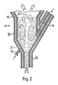
- Figure 2 shows a vertical section of the reactor 6, which comprises a cylindrical vessel 20, a lower frusto-conical part 21, the previously mentioned inlets 14 for calcined raw meal, 16 for fuel and 15 for combustion air as well as an exhaust gas passage 22 to the calciner 4.
- the reactor 6 is internally fitted with an insulating refractory lining.
- the calcined raw meal flows from the inlet pipe 14 down along the conical wall 21 of the reactor 6 and is captured at the bottom of the conical part 21 by the combustion air flowing up through the duct 15, thus forming a spouted bed in the cylindrical 20 of the reactor.
- the material is circulating in the reactor in a characteristic vertical pattern and is progressively built up into clinker with increasing particle dimensions.
- the finished clinker will fall down into the conical part 21 and move down through the pipe 15 to the first cooler 7.
- the predetermined size of the clinker depends on the setting of the volume and thereby the velocity of the air flowing up through the pipe 15.
- the pipe 15 has a free opening down into the cooler 7, providing a very simple classifier for the finish-burned clinker.
- the calcined raw meal being fed to the reactor 6 is practically fully calcined in that the raw meal has been calcined in the calciner to a degree of calcination of more than 98% and at a temperature higher than 950°C. Because of the exothermic process in the reactor it will, under certain circumstances, not be necessary to add fuel to the reactor, but the reactor is provided with the fuels supply pipe 16 in case the temperature for burning of cement clinker is not automatically elevated to a required level.
- the solution with a reactor according to the present invention offers a much simpler apparatus than known from the prior art, namely an apparatus without pressure loss-incurring connections between the calciner 4 and the reactor 6 and between the reactor 6 and the first cooler 7.
- the flow of combustion air to the stationary reactor can be set to much higher than the minimum air volume required for combustion of maximum fuel in the reactor, so that the temperature in the reactor can be controlled solely by adjusting the fuel supply without changing the air volume, thus maintaining the desired size of clinker which falls down through the pipe 15 to the cooler 7.
- the air flow up through the pipe 15 and hence the clinker size of the finish-burned clinker can thus be controlled solely by means of the blower 17.
- Figure 3 shows a variant of Figure 1, where the plant further comprises means for removal of a portion of the exhaust gas from the reactor 6 prior to entry of the exhaust gas unto the calciner 4 so as to reduce the alkali content in the clinker.
- the alkalis will evaporate, provided that the temperature in the spouted bed is sufficiently high, and some of these alkalis can then be extracted together with the above-mentioned portion of the exhaust gas.
- a fan 23 is provided for extracting the exhaust gas/alkali portion from the reactor 6 via an outlet 24 and, for example as shown, vented to a mixing chamber 25 in which the exhaust gas is mixed with fresh air and passed throught a cooling tower 26 where water is added.
- the alkalis thus condensed can subsequently be separated in a precipitator, not shown, and the exhaust gas vented to a stack.
Landscapes
- Engineering & Computer Science (AREA)
- Chemical & Material Sciences (AREA)
- Dispersion Chemistry (AREA)
- Mechanical Engineering (AREA)
- General Engineering & Computer Science (AREA)
- Curing Cements, Concrete, And Artificial Stone (AREA)
- Furnace Details (AREA)
- Crucibles And Fluidized-Bed Furnaces (AREA)
- Vertical, Hearth, Or Arc Furnaces (AREA)
Applications Claiming Priority (2)
| Application Number | Priority Date | Filing Date | Title |
|---|---|---|---|
| GB8901082A GB2227301A (en) | 1989-01-18 | 1989-01-18 | Method and apparatus for producing cement clinker |
| GB8901082 | 1989-01-18 |
Publications (3)
| Publication Number | Publication Date |
|---|---|
| EP0380878A2 true EP0380878A2 (fr) | 1990-08-08 |
| EP0380878A3 EP0380878A3 (en) | 1990-08-29 |
| EP0380878B1 EP0380878B1 (fr) | 1994-08-03 |
Family
ID=10650223
Family Applications (1)
| Application Number | Title | Priority Date | Filing Date |
|---|---|---|---|
| EP89313079A Expired - Lifetime EP0380878B1 (fr) | 1989-01-18 | 1989-12-14 | Méthode et installation pour la production de clinker de ciment |
Country Status (10)
| Country | Link |
|---|---|
| US (1) | US4997363A (fr) |
| EP (1) | EP0380878B1 (fr) |
| JP (1) | JP3042850B2 (fr) |
| CN (1) | CN1030309C (fr) |
| AU (1) | AU627825B2 (fr) |
| BR (1) | BR9000174A (fr) |
| DE (1) | DE68917285T2 (fr) |
| ES (1) | ES2057152T3 (fr) |
| GB (1) | GB2227301A (fr) |
| IN (1) | IN173236B (fr) |
Cited By (3)
| Publication number | Priority date | Publication date | Assignee | Title |
|---|---|---|---|---|
| WO1996015076A1 (fr) * | 1994-11-11 | 1996-05-23 | F.L. Smidth & Co. A/S | Procede de fabrication de clinker de ciment en four fixe |
| WO1997028408A1 (fr) * | 1996-02-02 | 1997-08-07 | F.L. Smidth & Co. A/S | Appareil destine au traitement en continu d'une matiere particulaire et procede correspondant |
| WO2018153678A1 (fr) * | 2017-02-22 | 2018-08-30 | Thyssenkrupp Industrial Solutions Ag | Installation de production de clinkers de ciment et procédé de fonctionnement d'une telle installation |
Families Citing this family (13)
| Publication number | Priority date | Publication date | Assignee | Title |
|---|---|---|---|---|
| DE3829853C1 (fr) * | 1988-09-02 | 1989-11-30 | O & K Orenstein & Koppel Ag, 1000 Berlin, De | |
| US5173044A (en) * | 1990-05-15 | 1992-12-22 | F. L. Smidth & Co. A/S | Method and apparatus for the manufacture of clinker of mineral raw materials |
| TWI359124B (en) * | 2003-10-29 | 2012-03-01 | Smidth As F L | Method and plant for preheating particulate or pul |
| FR2876782B1 (fr) * | 2004-10-19 | 2007-02-16 | Technip France Sa | Installation et procede de calcination d'une charge minerale contenant un carbonate pour produire un liant hydraulique |
| US7361014B2 (en) * | 2005-11-15 | 2008-04-22 | Buzzi Unicem Usa, Inc. | Injection of waste-derived materials into pre-calcining stage of a clinker production system |
| JP5178503B2 (ja) * | 2006-02-14 | 2013-04-10 | 株式会社クレハ | 連続式粉粒体高温ガス処理装置および処理方法 |
| CN100443843C (zh) * | 2007-02-15 | 2008-12-17 | 缪建通 | 节能环保水泥熟料煅烧窑自动化控制方法 |
| ATE532019T1 (de) * | 2007-08-07 | 2011-11-15 | Thyssenkrupp Polysius Ag | Vorrichtung zur separierung von einem feststoff und einem gas sowie anlage zur zementherstellung |
| ATE520943T1 (de) * | 2008-06-25 | 2011-09-15 | Thyssenkrupp Polysius Ag | Vorrichtung zur durchführung chemischer und/oder physikalischer reaktionen zwischen einem feststoff und einem gas |
| FR2951258B1 (fr) | 2009-10-08 | 2012-09-07 | Fives Fcb | Procede de refroidissement de matieres solides granuleuses et installation de cuisson continue en tant que telle |
| US10598434B2 (en) * | 2015-10-08 | 2020-03-24 | Flsmidth A/S | Multi-stage cement calcining plant suspension preheater |
| WO2019116350A1 (fr) | 2017-12-15 | 2019-06-20 | Flsmidth A/S | Appareil séparateur de minéral broyé non traité de ciment et son procédé d'utilisation |
| JP7326333B2 (ja) | 2018-05-15 | 2023-08-15 | エフ・エル・スミス・エー・エス | 粒子を処理するための排出低減装置、および同排出低減装置を使用する方法 |
Family Cites Families (15)
| Publication number | Priority date | Publication date | Assignee | Title |
|---|---|---|---|---|
| GB960863A (en) * | 1960-09-13 | 1964-06-17 | Dessau Zementanlagenbau Veb | Process for the calcination of raw silicate material |
| GB1463124A (en) * | 1974-06-18 | 1977-02-02 | Smidth & Co As F L | Calcination of pulverous material |
| GB1434339A (en) * | 1974-10-03 | 1976-05-05 | Smidth & Co As F L | Coolers for cooling granular or pulverous material |
| US4425092A (en) * | 1978-08-02 | 1984-01-10 | Klockner-Humboldt-Deutz Ag | System for burning fine-grained material, particularly for the manufacture of cement clinkers |
| JPS55136154A (en) * | 1979-04-03 | 1980-10-23 | Sumitomo Cement Co | Method and device for utilizing combustible matter |
| DE2938144A1 (de) * | 1979-09-21 | 1981-04-02 | Claudius Peters Ag, 2000 Hamburg | Ofenanlage |
| FR2474334A1 (fr) * | 1980-01-28 | 1981-07-31 | Lafarge Sa | Dispositif de melange avec turbulence de fluides gazeux |
| DE3134798A1 (de) * | 1981-09-02 | 1983-03-17 | Klöckner-Humboldt-Deutz AG, 5000 Köln | Brennanlage, insbesondere zur herstellung von zementklinker |
| JPS58115047A (ja) * | 1981-12-28 | 1983-07-08 | 石川島播磨重工業株式会社 | 粉末原料の焼成設備 |
| JPS60264350A (ja) * | 1984-06-11 | 1985-12-27 | 秩父セメント株式会社 | 白セメントクリンカの製造方法とその装置 |
| US4595416A (en) * | 1984-10-01 | 1986-06-17 | Fuller Company | Method and apparatus for producing cement clinker including white cement |
| DE3521520A1 (de) * | 1985-06-15 | 1986-12-18 | Helmut Dipl.-Ing. 8770 Lohr Pieper | Verfahren und anlage zur herstellung von geblaehten pellets aus glasbildende silikate enthaltenden stoffen |
| DE3538707A1 (de) * | 1985-10-31 | 1987-05-07 | Kloeckner Humboldt Deutz Ag | Verfahren und vorrichtung zur thermischen behandlung von mehlfoermigen rohmaterialien |
| JPS62112984A (ja) * | 1985-11-13 | 1987-05-23 | 秩父セメント株式会社 | 粉末原料の流動焼成用仮焼装置 |
| CA1285761C (fr) * | 1986-04-01 | 1991-07-09 | Kawasaki Jukogyo Kabushiki Kaisha | Installation pour la fabrication du clinker de ciment |
-
1989
- 1989-01-18 GB GB8901082A patent/GB2227301A/en not_active Withdrawn
- 1989-12-11 US US07/448,745 patent/US4997363A/en not_active Expired - Lifetime
- 1989-12-12 IN IN918MA1989 patent/IN173236B/en unknown
- 1989-12-14 DE DE68917285T patent/DE68917285T2/de not_active Expired - Fee Related
- 1989-12-14 EP EP89313079A patent/EP0380878B1/fr not_active Expired - Lifetime
- 1989-12-14 ES ES89313079T patent/ES2057152T3/es not_active Expired - Lifetime
-
1990
- 1990-01-16 CN CN90100229.1A patent/CN1030309C/zh not_active Expired - Fee Related
- 1990-01-17 JP JP2008080A patent/JP3042850B2/ja not_active Expired - Fee Related
- 1990-01-17 BR BR909000174A patent/BR9000174A/pt not_active IP Right Cessation
- 1990-01-18 AU AU48595/90A patent/AU627825B2/en not_active Ceased
Cited By (7)
| Publication number | Priority date | Publication date | Assignee | Title |
|---|---|---|---|---|
| WO1996015076A1 (fr) * | 1994-11-11 | 1996-05-23 | F.L. Smidth & Co. A/S | Procede de fabrication de clinker de ciment en four fixe |
| AU683774B2 (en) * | 1994-11-11 | 1997-11-20 | F.L. Smidth & Co A/S | Method for manufacturing cement clinker in a stationary burning reactor |
| WO1997028408A1 (fr) * | 1996-02-02 | 1997-08-07 | F.L. Smidth & Co. A/S | Appareil destine au traitement en continu d'une matiere particulaire et procede correspondant |
| AU699241B2 (en) * | 1996-02-02 | 1998-11-26 | F.L. Smidth & Co A/S | Method and apparatus for continuous treatment of particulate material |
| US6000145A (en) * | 1996-02-02 | 1999-12-14 | F. L. Smidth & Co. A/S | Method and apparatus for continuous treatment of particulate material |
| RU2150060C1 (ru) * | 1996-02-02 | 2000-05-27 | Ф.Л. Смидт Энд Ко. А/С | Способ и устройство для непрерывной обработки зернистого материала |
| WO2018153678A1 (fr) * | 2017-02-22 | 2018-08-30 | Thyssenkrupp Industrial Solutions Ag | Installation de production de clinkers de ciment et procédé de fonctionnement d'une telle installation |
Also Published As
| Publication number | Publication date |
|---|---|
| GB2227301A (en) | 1990-07-25 |
| CN1044449A (zh) | 1990-08-08 |
| IN173236B (fr) | 1994-03-12 |
| US4997363A (en) | 1991-03-05 |
| ES2057152T3 (es) | 1994-10-16 |
| AU627825B2 (en) | 1992-09-03 |
| CN1030309C (zh) | 1995-11-22 |
| EP0380878B1 (fr) | 1994-08-03 |
| JP3042850B2 (ja) | 2000-05-22 |
| DE68917285D1 (de) | 1994-09-08 |
| JPH02243545A (ja) | 1990-09-27 |
| EP0380878A3 (en) | 1990-08-29 |
| GB8901082D0 (en) | 1989-03-15 |
| AU4859590A (en) | 1990-07-26 |
| DE68917285T2 (de) | 1994-11-24 |
| BR9000174A (pt) | 1990-10-23 |
Similar Documents
| Publication | Publication Date | Title |
|---|---|---|
| EP0380878B1 (fr) | Méthode et installation pour la production de clinker de ciment | |
| CA1085612A (fr) | Appareil servant a produire du clinker de ciment | |
| US4569831A (en) | Process and apparatus for calcining gypsum | |
| EP1575700A1 (fr) | Procede et appareil de traitement thermique dans un lit fluidise | |
| EP0153048B1 (fr) | Système de préchauffage de fines à calcination préliminaire | |
| EP1575871A1 (fr) | Procede et appareil de production d'oxyde metallique a partir de composes metalliques | |
| DK155791B (da) | Fremgangsmaade til fremstilling af cementklinker | |
| US7287477B2 (en) | Cyclone bypass for a circulating fluidized bed reactor | |
| US4708644A (en) | Apparatus for roasting fine grained material | |
| EP0226329B1 (fr) | Appareil de calcination utilisé dans une installation de cuisson de matières en poudre | |
| AU699241B2 (en) | Method and apparatus for continuous treatment of particulate material | |
| JP3032198B1 (ja) | 石灰泥の焼成方法及び装置 | |
| JPS6156177B2 (fr) | ||
| JPS6022273B2 (ja) | 粉粒体の連続気流焼成炉 | |
| JPS5932175B2 (ja) | 流動焙焼装置 | |
| JPH0542386B2 (fr) | ||
| CA1051381A (fr) | Cyclone separateur a etages de captation | |
| JPH0431520Y2 (fr) | ||
| JPS6013739B2 (ja) | セメントなどの粉末原料の焼成方法 | |
| JPS6259390A (ja) | 複数系統型粉末原料予熱装置 | |
| JPH0327261B2 (fr) | ||
| JPH0424628B2 (fr) | ||
| JPS6013737B2 (ja) | セメントなどの粉末原料の焼成方法 | |
| JPS6283031A (ja) | 原料粉末等の焼成方法とその装置 |
Legal Events
| Date | Code | Title | Description |
|---|---|---|---|
| PUAI | Public reference made under article 153(3) epc to a published international application that has entered the european phase |
Free format text: ORIGINAL CODE: 0009012 |
|
| PUAL | Search report despatched |
Free format text: ORIGINAL CODE: 0009013 |
|
| AK | Designated contracting states |
Kind code of ref document: A2 Designated state(s): DE ES FR GB IT |
|
| AK | Designated contracting states |
Kind code of ref document: A3 Designated state(s): DE ES FR GB IT |
|
| 17P | Request for examination filed |
Effective date: 19910221 |
|
| 17Q | First examination report despatched |
Effective date: 19920401 |
|
| GRAA | (expected) grant |
Free format text: ORIGINAL CODE: 0009210 |
|
| AK | Designated contracting states |
Kind code of ref document: B1 Designated state(s): DE ES FR GB IT |
|
| ET | Fr: translation filed | ||
| REF | Corresponds to: |
Ref document number: 68917285 Country of ref document: DE Date of ref document: 19940908 |
|
| REG | Reference to a national code |
Ref country code: ES Ref legal event code: FG2A Ref document number: 2057152 Country of ref document: ES Kind code of ref document: T3 |
|
| ITF | It: translation for a ep patent filed | ||
| PLBE | No opposition filed within time limit |
Free format text: ORIGINAL CODE: 0009261 |
|
| STAA | Information on the status of an ep patent application or granted ep patent |
Free format text: STATUS: NO OPPOSITION FILED WITHIN TIME LIMIT |
|
| 26N | No opposition filed | ||
| REG | Reference to a national code |
Ref country code: GB Ref legal event code: IF02 |
|
| PGFP | Annual fee paid to national office [announced via postgrant information from national office to epo] |
Ref country code: DE Payment date: 20061207 Year of fee payment: 18 |
|
| PGFP | Annual fee paid to national office [announced via postgrant information from national office to epo] |
Ref country code: FR Payment date: 20061208 Year of fee payment: 18 |
|
| PGFP | Annual fee paid to national office [announced via postgrant information from national office to epo] |
Ref country code: GB Payment date: 20061213 Year of fee payment: 18 |
|
| PGFP | Annual fee paid to national office [announced via postgrant information from national office to epo] |
Ref country code: IT Payment date: 20061231 Year of fee payment: 18 |
|
| PGFP | Annual fee paid to national office [announced via postgrant information from national office to epo] |
Ref country code: ES Payment date: 20070122 Year of fee payment: 18 |
|
| GBPC | Gb: european patent ceased through non-payment of renewal fee |
Effective date: 20071214 |
|
| PG25 | Lapsed in a contracting state [announced via postgrant information from national office to epo] |
Ref country code: DE Free format text: LAPSE BECAUSE OF NON-PAYMENT OF DUE FEES Effective date: 20080701 |
|
| REG | Reference to a national code |
Ref country code: FR Ref legal event code: ST Effective date: 20081020 |
|
| PG25 | Lapsed in a contracting state [announced via postgrant information from national office to epo] |
Ref country code: GB Free format text: LAPSE BECAUSE OF NON-PAYMENT OF DUE FEES Effective date: 20071214 |
|
| REG | Reference to a national code |
Ref country code: ES Ref legal event code: FD2A Effective date: 20071215 |
|
| PG25 | Lapsed in a contracting state [announced via postgrant information from national office to epo] |
Ref country code: ES Free format text: LAPSE BECAUSE OF NON-PAYMENT OF DUE FEES Effective date: 20071215 Ref country code: FR Free format text: LAPSE BECAUSE OF NON-PAYMENT OF DUE FEES Effective date: 20071231 |
|
| PG25 | Lapsed in a contracting state [announced via postgrant information from national office to epo] |
Ref country code: IT Free format text: LAPSE BECAUSE OF NON-PAYMENT OF DUE FEES Effective date: 20071214 |