EP0380892A1 - Ultraminiaturisierte Hochfrequenz-Steckverbindungszwischenstelle - Google Patents
Ultraminiaturisierte Hochfrequenz-Steckverbindungszwischenstelle Download PDFInfo
- Publication number
- EP0380892A1 EP0380892A1 EP89403516A EP89403516A EP0380892A1 EP 0380892 A1 EP0380892 A1 EP 0380892A1 EP 89403516 A EP89403516 A EP 89403516A EP 89403516 A EP89403516 A EP 89403516A EP 0380892 A1 EP0380892 A1 EP 0380892A1
- Authority
- EP
- European Patent Office
- Prior art keywords
- connector
- conductor
- interface according
- sleeve
- peripheral conductor
- Prior art date
- Legal status (The legal status is an assumption and is not a legal conclusion. Google has not performed a legal analysis and makes no representation as to the accuracy of the status listed.)
- Ceased
Links
- 239000004020 conductor Substances 0.000 claims abstract description 87
- 230000002093 peripheral effect Effects 0.000 claims description 38
- 230000006978 adaptation Effects 0.000 claims description 6
- 239000000463 material Substances 0.000 claims description 6
- PXHVJJICTQNCMI-UHFFFAOYSA-N Nickel Chemical compound [Ni] PXHVJJICTQNCMI-UHFFFAOYSA-N 0.000 claims description 4
- 238000005476 soldering Methods 0.000 claims description 4
- 239000011521 glass Substances 0.000 claims description 3
- 229910052751 metal Inorganic materials 0.000 claims description 3
- 239000002184 metal Substances 0.000 claims description 3
- 230000002787 reinforcement Effects 0.000 claims description 3
- 238000011144 upstream manufacturing Methods 0.000 claims description 3
- 229910001369 Brass Inorganic materials 0.000 claims description 2
- 239000011324 bead Substances 0.000 claims description 2
- DMFGNRRURHSENX-UHFFFAOYSA-N beryllium copper Chemical compound [Be].[Cu] DMFGNRRURHSENX-UHFFFAOYSA-N 0.000 claims description 2
- 239000010951 brass Substances 0.000 claims description 2
- 238000005520 cutting process Methods 0.000 claims description 2
- 229910052759 nickel Inorganic materials 0.000 claims description 2
- 239000013013 elastic material Substances 0.000 claims 1
- 238000000465 moulding Methods 0.000 claims 1
- 230000000284 resting effect Effects 0.000 claims 1
- 230000008878 coupling Effects 0.000 abstract description 6
- 238000010168 coupling process Methods 0.000 abstract description 6
- 238000005859 coupling reaction Methods 0.000 abstract description 6
- 230000014759 maintenance of location Effects 0.000 abstract description 2
- 239000007787 solid Substances 0.000 abstract 1
- 238000002788 crimping Methods 0.000 description 5
- 241000209140 Triticum Species 0.000 description 2
- 235000021307 Triticum Nutrition 0.000 description 2
- 235000013339 cereals Nutrition 0.000 description 2
- 230000000694 effects Effects 0.000 description 2
- 238000003780 insertion Methods 0.000 description 2
- 230000037431 insertion Effects 0.000 description 2
- 230000003993 interaction Effects 0.000 description 2
- 238000003754 machining Methods 0.000 description 2
- 230000009467 reduction Effects 0.000 description 2
- 229910000863 Ferronickel Inorganic materials 0.000 description 1
- 229910045601 alloy Inorganic materials 0.000 description 1
- 239000000956 alloy Substances 0.000 description 1
- 230000004075 alteration Effects 0.000 description 1
- 230000005540 biological transmission Effects 0.000 description 1
- 239000000470 constituent Substances 0.000 description 1
- 230000003247 decreasing effect Effects 0.000 description 1
- 230000001627 detrimental effect Effects 0.000 description 1
- 239000003989 dielectric material Substances 0.000 description 1
- 230000005489 elastic deformation Effects 0.000 description 1
- 238000005516 engineering process Methods 0.000 description 1
- 238000009434 installation Methods 0.000 description 1
- 238000009413 insulation Methods 0.000 description 1
- 239000012212 insulator Substances 0.000 description 1
- 238000004519 manufacturing process Methods 0.000 description 1
- 238000000034 method Methods 0.000 description 1
- 238000003825 pressing Methods 0.000 description 1
- 230000000750 progressive effect Effects 0.000 description 1
- 230000005855 radiation Effects 0.000 description 1
- 230000000630 rising effect Effects 0.000 description 1
- 239000010935 stainless steel Substances 0.000 description 1
- 229910001220 stainless steel Inorganic materials 0.000 description 1
- 230000007704 transition Effects 0.000 description 1
- 238000003466 welding Methods 0.000 description 1
Images


Classifications
-
- H—ELECTRICITY
- H01—ELECTRIC ELEMENTS
- H01R—ELECTRICALLY-CONDUCTIVE CONNECTIONS; STRUCTURAL ASSOCIATIONS OF A PLURALITY OF MUTUALLY-INSULATED ELECTRICAL CONNECTING ELEMENTS; COUPLING DEVICES; CURRENT COLLECTORS
- H01R24/00—Two-part coupling devices, or either of their cooperating parts, characterised by their overall structure
- H01R24/38—Two-part coupling devices, or either of their cooperating parts, characterised by their overall structure having concentrically or coaxially arranged contacts
- H01R24/40—Two-part coupling devices, or either of their cooperating parts, characterised by their overall structure having concentrically or coaxially arranged contacts specially adapted for high frequency
- H01R24/42—Two-part coupling devices, or either of their cooperating parts, characterised by their overall structure having concentrically or coaxially arranged contacts specially adapted for high frequency comprising impedance matching means or electrical components, e.g. filters or switches
- H01R24/44—Two-part coupling devices, or either of their cooperating parts, characterised by their overall structure having concentrically or coaxially arranged contacts specially adapted for high frequency comprising impedance matching means or electrical components, e.g. filters or switches comprising impedance matching means
-
- H—ELECTRICITY
- H01—ELECTRIC ELEMENTS
- H01R—ELECTRICALLY-CONDUCTIVE CONNECTIONS; STRUCTURAL ASSOCIATIONS OF A PLURALITY OF MUTUALLY-INSULATED ELECTRICAL CONNECTING ELEMENTS; COUPLING DEVICES; CURRENT COLLECTORS
- H01R2103/00—Two poles
Definitions
- the invention relates to high frequency connections, and more particularly to microwave or microwave.
- the connectors in question are coaxial or else multiaxial, for example triaxial. Although the invention applies generally to all these types of connectors, the present description essentially considers coaxial connectors.
- such connectors can be interposed either between two coaxial cables, or between a coaxial cable and a printed circuit board, or even between a coaxial cable and a microwave device.
- the connectors must, like the cables, comply with certain electrical characteristics, within their operating frequency band. These electrical characteristics are, essentially, the standing wave ratio or rate, the characteristic impedance and the insertion losses.
- Compliance with these characteristics depends mainly on the internal geometry of the connectors, and on the nature of the dielectric used and its shape, in an interdependent manner.
- the interface consisting of a pair of microwave connectors must therefore perform an electrical function having, in the microwave band concerned, on the one hand, continuous electrical connections concerning the internal contacts between them and the external contacts between them, on the other hand the continuous presence of one or more dielectrics between the interior contacts and the exterior contacts, the latter being capable of being grounded.
- connection interfaces for high frequency are already known comprising two conjugate connector elements (or more simply connectors) having a generally cylindrical shape, each with at least one central conductor and one peripheral conductor separated by a dielectric.
- the elements of the connectors are in the form of a shouldered cylinder of various diameters, fitted concentrically into each other, although the coaxial structure is not strictly imperative.
- the connectors in question must have electrical qualities of the same order as those required for current professional coaxial connectors which are of a size that can be easily handled.
- the main object of the present invention is to provide a solution to the problem of producing very small microwave connectors, typically with an overall external diameter of approximately 3 to 4 mm, or less.
- the external surface of its dielectric sleeve defines a bearing surface with a stop on the side opposite to the other connector
- the peripheral conductor is constructed from a rigid zone engaged on said bearing surface, with on one side bearing on said abutment, on the other, recessed radial recess in the form of an elastic nose which projects beyond said bearing surface, while its end portion, split, is provided at the end with a external lateral chamfered edge
- the inner wall of the peripheral conductor of the second connector comprises, opposite the first connector, a first bore capable of receiving the sleeve from the rear, in abutment on its rear part, while defining at the front, with the face radial of the sleeve, an annular recess capable of accommodating said rim, then a second bore, homologous to said split nose, and finally an end stop capable of cooperating with the radial recess of the first connector, and accompanied by an internal lateral chamfer.
- the interface span between the two connectors is located between the end stop of the peripheral conductor of the second connector and the radial offset of the peripheral conductor of the first connector.
- Mechanical centering is achieved by cooperation between the internal bore of the peripheral conductor of the second connector and the external contour of the nose of the first connector, in particular in its unsplit area.
- the two connectors are held in position by the cooperation, in the longitudinal direction, of the chamfered edge of the first connector and the annular recess of the second connector.
- the external electrical contact the quality of which is essential, is ensured by the cooperation in the radial direction of the same parts.
- said edge of the peripheral conductor of the first connector comprises a downstream chamfer (facing the other connector) at an angle of approximately 30 ° as well as an upstream chamfer at an angle of approximately 45 °, while the input of the peripheral conductor of the second connector has a cylindrical pre-centering zone, followed by an internal downstream chamfer with an angle of about 30 °. This considerably facilitates the introduction of the two connectors into each other.
- the second connector has a male central conductor provided with a radial collar suitable for pressing on its dielectric sleeve, at the same time as carrying out an impedance adaptation at high frequency;
- the first connector has a split female central conductor, the part of which extends beyond the sleeve is provided with an additional thickness forming an adaptation appendage at high frequency, at the same time as a reinforcement increasing the security of insertion of the male contact, and suitable nevertheless for being engaged through the central orifice of the dielectric sleeve of the first connector.
- the proposed structure adapts well to this case where the first connector carries the female central conductor. This is then housed in a sheath extending the dielectric sleeve of the first connector with reduction in diameter. The bottom of the blind hole of this central conductor can be located substantially in line with said radial recess of the peripheral conductor of this first connector. For its part, the male central conductor is housed in abutment on a right radial face of the sleeve of the second connector.
- these central conductors have homologous chamfers with an angle of about 45 °.
- peripheral conductors it is also advantageous for the peripheral conductors to extend beyond the central conductors.
- the external contour of the peripheral conductor can be prismatic, at least for the second connector.
- This characteristic which also applies to the first connector, considerably facilitates the gripping and manual coupling of the two connectors. It is worth remembering that, when two parts are placed by hand, any difficulty in handling results in unnecessarily high forces which, in turn, unnecessarily cause the mechanical parts concerned to suffer. It has been observed that the characteristics set out above make it possible, for the connectors of the present invention, to avoid numerous causes of material rupture which are obviously disastrous in such circumstances.
- the peripheral conductor of the second connector is extended at its free end by an expansion of prismatic internal contour.
- the rigid zone of the peripheral conductor of the first connector must externally have a prismatic contour combined with the previous one. This prevents any relative rotation of the two connectors, thereby significantly improving their resistance to vibration.
- this characteristic can also be used more generally to compensate for any torsional force between the two connectors, whether these are of the coaxial type or else of the multiaxial type.
- One of the components of the problem to be solved consists in obtaining connectors of reduced dimensions capable of being coupled to form an interface of dimensions optimized to allow manipulation thereof.
- the word conductor is used to define the conductive parts incorporated in the connector, although these are also sometimes designated by the term "contact”.
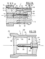
- FIGS 1A and 1B on the one hand, 2A and 2B on the other hand describe pairs of almost identical connectors, except that those of Figures 2 are provided with an anti-rotation device.
- the reference 1 designates the connector on the left, that is to say the connection part of which faces towards the right, while the reference 2 designates the connector on the right, the connection part of which faces towards the left.
- the connector 1 comprises a central connector generally designated by 10, the material of which can be chosen as required. To the right, this connector has a female area 101, or hole, provided with four slots regularly distributed on its periphery such as 102, parallel to the axis of the cylindrical generator. The hole of the central conductor ends in a chamfer flared 103 at an angle of about 45 °. The whole of this central conductor is fitted into the central bore of a dielectric sleeve 12. Externally, the latter has a bearing surface 121, terminated to the left by a stop 122, or protruding shoulder.
- a re-entering shoulder 125 which here terminates in a sheath 127 extending the sleeve 12 to accommodate most of the female zone of the central conductor 10.
- the reference 129 designates the end of the sleeve on the downstream, i.e. on the side of the other connector.
- a peripheral conductor 16 is engaged. It comprises a reinforced zone 160, of great thickness, therefore relatively rigid.
- the peripheral conductor can be heat-treated beryllium copper and gilded on a nickel sublayer. This material, elastic in thin thickness can become relatively rigid in large thickness.
- This rigid zone 160 is provided with a shoulder 161 which bears on the stop 122 of the dielectric sleeve 12. To the left, the conductor 16 can be held on the sleeve 12 by force fitting, or by the presence of groove, or by any other technique giving the assembly great rigidity.
- the diameter of the flange 110 of the central conductor 10 can be reduced enough to allow the mounting of this conductor from the rear, because the flange then crosses the hole 131 of the dielectric 12. This possibility is very important in practice.
- the rigid area 160 has a surface 162 which is cylindrical, or better prismatic, was only for gripping reasons.
- the area rigid ends with a re-entrant shoulder 165 which allows the material of the part 160 to now define a fine structure of generally cylindrical shape advancing to the right, which will be called "nose".
- the nose 170 is full and rests on the bearing 121. As soon as it extends beyond it, it is provided with a plurality of slots regularly distributed around the periphery of the cylinder, such as 172. These slots are at least 4 in number, but it is preferred here to use 6 or 8 to improve flexibility.
- the nose 170 ends on the right by a rim 180 which respects the shape of revolution of the assembly.
- This nose 180 has, on the left, that is to say upstream, a rising chamfer 182 at an angle of about 45 °. This first chamfer is followed by a flat nose 183, followed in turn by a descending chamfer 181 at an angle of about 30 °.
- the other connector is illustrated in Figures 1B and 2B. Its dielectric sleeve is simpler (at least when the male central conductor is housed), since it can be reduced as visible at 22 to a simple thick cylindrical ring.
- the ring houses the part forming a pin for holding the central conductor 20.
- the latter comprises on the left a contact part 201 terminated by a chamfer 203 with an angle homologous to that of the chamfer 103, it that is to say about 45 °.
- the peripheral conductor 26 is integral with the cylindrical bearing face 221 of the sleeve 22. Its outer surface 269 is cylindrical or, preferably, prismatic to improve the grip. Internally, this peripheral conductor 26 firstly has a recess 280 close to the dielectric sleeve 22 and suitable for housing the abovementioned flange 180. To the left there is then a bore 270 which corresponds precisely to the diameter be from part 170 of the nose of the other connector. This bore ends with a flare 281 and a cylindrical pre-centering zone 262, which precedes the proper stop coming into contact on the homologous stop zone 165 of the other connector.
- FIGS. 1B and 2B It is essentially here that the drawings of FIGS. 1B and 2B will differ.
- the stop of the connector 2 is simply defined by a radial support face 265.
- this stop is defined by a slight step 265 followed by an extension 290 whose internal cylindrical face 262 is of prismatic shape (the word cylinder is used here in its sense of mathematical geometry, where it covers any supported surface on a contour, whether it is curved or in the form of a broken line).
- This embodiment of FIG. 2B requires that the part 162 of FIG. 2A be of prismatic shape, and that the prismatic shapes of this part 162 and of the face 262 are homologous, so that after having completely come into engagement, the two conductors are immobilized in relative rotation by these two homologous prismatic forms.
- the material of the peripheral conductor 26 does not need elasticity. We can therefore choose for example free cutting brass, which is a good conductor and easily machinable.
- peripheral conductor extends beyond the free end of the central conductor, which is useful in particular for mechanically protecting said central conductor.
- the free end of the female conductor 10 is provided with a portion 110 in excess thickness, where it exits from the sheath 127.
- This portion in excess thickness not only makes it possible to obtain better rigidity in the area where it will begin. sinking, which is important to avoid breaks but also to provide a microwave adaptation appendage function, which substantially improves the quality of connection.
- the flange 210 formed on the male central contact 20 is advantageously combined with the flange 210 formed on the male central contact 20, this flange also being able, on the one hand, to serve as a support on the left radial face of the dielectric sleeve 22, on the other hand the electrical adaptation of the microwave link.
- the cooperation of the bore 270 and the external surface of the nose 170 ensures, in a very simple, gentle and progressive manner, an excellent centering of the two connectors during their coupling.
- This coupling operation being completed, the two connec teurs are held in position by cooperation of the chamfer 182 with the left shoulder of the recess 280.
- the retention thus obtained is excellent.
- the other chamfer 181 will have been used in cooperation with the surfaces 282 and 281 to ensure the entry of the nose into the bore 270, with elastic deformation thereof, preparing for centering, with both great flexibility and effort sufficient to avoid any deformation or breakage of the components of the two connectors.
- the insulating sleeve 22 is advantageously molded, which allows crimping of the peripheral conductor thereon, without changing the internal diameter. Its external surface has at 226 longitudinal edges or grooves allowing its hard mounting in the bore 221.
- the sleeve 22 has tabs 225 (for example 4) abutting on the rear radial face 266 of the peripheral conductor 26.
- this rear face 266 is provided with machined tabs 267 crimped onto the dielectric to immobilize it.
- This arrangement leads to a minimum space requirement, taking into account the fact that the small thickness of the conductor 26 does not allow the dielectric to be held by a stop shoulder.
- the internal machining of this conductor 26 can be carried out with a single tool, therefore with great precision, even for a very small diameter.
- the firm immobilization of the dielectric ensures the correct dimensioning of the recess 280.
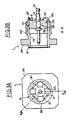
- the central conductor, grooved at 208, is mounted hard in the dielectric sleeve 22.
- the rear central connection is made on a hollow pin 29, while the external conductor is connected to a chassis by its thread 268 and the external stop shoulder 269.
- the rear part of the external conductor 26 can widen in polygonal cross-section, for example square, with 3 pins 271 or more, which, like the pin 291 of the central conductor, are suitable for mounting on printed circuit.
- 3 pins 271 or more which, like the pin 291 of the central conductor, are suitable for mounting on printed circuit.
- the rest is similar to Figures 3A and 3B.
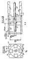
- Figure 5 is illustrated a second connector forming a hermetic assembly.
- a glass bead 22 pre-equipped with the central conductor 20, and, at the periphery, a brazable metallic hoop 229. This is inserted in the bore 280 with fixing in the form of a bra sure by preform on template interesting the hoop itself, and reinforcement by a rear brazed zone 230.
- Another alternative embodiment consists in producing at least one of the conductors in a ferro-nickel alloy or in stainless steel, which is compatible with the use of a glass dielectric.
- the peripheral conductor of the first connector can be either in one piece, or produced in two parts 162A and 162B, connected for example by hard mounting and crimping at the level of the part which defines the rigid area.
- the crimping lugs 169 are provided in the corners of a square enlargement of the conductor 16.
- FIGS. 6A and 6B also show how the connector can be produced in an angled manner with a reference to a coaxial cable, which can be crimped, or alternatively, welded.
- the insulator 12 has an axial extension 129 delimiting a cavity where the central conductor provides a soldering slot 109 for the core 30 of the coaxial cable 3.
- the cavity is closed, with a radial dielectric plate 130, held by soldering d 'a metal cover 135 on the rear of the external conductor body 16.
- This body can be extended laterally by a sleeve comprising reliefs 140 on which the braid 36 of the cable 3 is extended.
- An external metal cylinder 49 allows the crimping of this braid 36 on the checkered sleeve 140.
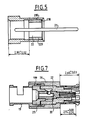
- FIG. 7 illustrates a first connector in a straight version (not bent).
- the rear of the central conductor 20 defines a housing with lateral access for soldering the core of a coaxial cable.
- This rear part is held by a dielectric ring 25 bearing externally on both the dielectric 22 and the internal bore 199 of a braid welding or crimping cylinder 19.
- a factory pre-assembly of the elements 19, 199, and 20 considerably facilitates the installation of the coaxial cable by the user.
- the female (or male) socket thus formed extends practically without additional thickness a coaxial cable having the dimensions of FIG. 6B.
- the rear connection of the connectors according to the invention can be the subject of several variants, applicable to each connector element: - connection by soldered pins in the holes of printed circuit boards, - connection by legs brazed on the surface on printed circuit boards (called CMS or SMT), - connection to printed boards or microwave devices by flexible circuit of technology called "strip line", - connection on flexible coaxial cables, - connection on coaxial cables of the semi-rigid type, - integral connection with an active or passive microwave body, such as an antenna, a radiating cavity or a transition between a microwave waveguide and a coaxial cable.
- CMS printed circuit boards
- strip line flexible circuit of technology
- FIGS. 8A and 8B respectively illustrate the active part of a connector of the first type and of a connector of the second type according to the present invention, with an indication of the dimensions and tolerances applicable to such a connector.
- PF designates the reference plane of the interface once connected, ie, the contact plane of the two connector elements.
- a certain number of essential dimensions are related to this reference plane. All dimensions are expressed in millimeters, while tolerances are expressed in hundredths of a millimeter.
- the dimensions marked with an asterisk refer to the variant of FIGS. 2A and 2B. They express that the outer periphery of the first connector (FIG. 8A) has dishes, two in number, and at least 0.6 height, dishes which are capable of cooperating with the opening of dimension 3.20 appearing in FIG. 8B .
- the invention makes it possible to directly obtain all the desired dimensions at the level of the machining phase. There is however an exception, which concerns the realization of the nose. Indeed, as it appears in FIG. 8A, the nose is machined with an external dimension of 2.55 mm. It is then threaded on a cone to be reopened at the nominal dimension of 2.70 mm
- a similar operation can possibly be carried out for the female central contact, but in the opposite direction, that is to say by making a pinching of this contact at its input, rather than a reopening.
- FIGS. 8A and 8B are, under the conditions indicated above, to be considered as an integral part of the invention.
Landscapes
- Coupling Device And Connection With Printed Circuit (AREA)
Applications Claiming Priority (2)
| Application Number | Priority Date | Filing Date | Title |
|---|---|---|---|
| FR8900708 | 1989-01-20 | ||
| FR8900708A FR2642232B1 (fr) | 1989-01-20 | 1989-01-20 | Interface de connexion ultra miniature pour haute frequence |
Publications (1)
| Publication Number | Publication Date |
|---|---|
| EP0380892A1 true EP0380892A1 (de) | 1990-08-08 |
Family
ID=9377939
Family Applications (1)
| Application Number | Title | Priority Date | Filing Date |
|---|---|---|---|
| EP89403516A Ceased EP0380892A1 (de) | 1989-01-20 | 1989-12-15 | Ultraminiaturisierte Hochfrequenz-Steckverbindungszwischenstelle |
Country Status (3)
| Country | Link |
|---|---|
| US (1) | US5074809A (de) |
| EP (1) | EP0380892A1 (de) |
| FR (1) | FR2642232B1 (de) |
Cited By (2)
| Publication number | Priority date | Publication date | Assignee | Title |
|---|---|---|---|---|
| JP2024516245A (ja) * | 2021-04-30 | 2024-04-12 | エドワーズ リミテッド | 真空ポンプ用ステータ |
| US11984686B2 (en) | 2019-11-14 | 2024-05-14 | Te Connectivity Germany Gmbh | HF terminal for an HF connector, and a method for improving the quality of a signal integrity of a male HF connector or of an HF plug-in connector |
Families Citing this family (72)
| Publication number | Priority date | Publication date | Assignee | Title |
|---|---|---|---|---|
| US5154635A (en) * | 1990-08-31 | 1992-10-13 | Kaufman Harold R | Coaxial vacuum cable |
| US5324311A (en) * | 1992-09-04 | 1994-06-28 | Siemens Pacesetter, Inc. | Coaxial bipolar connector assembly for implantable medical device |
| US5242316A (en) * | 1992-11-23 | 1993-09-07 | Dynawave Incorporated | Microwave coaxial connector |
| US5456611A (en) * | 1993-10-28 | 1995-10-10 | The Whitaker Corporation | Mini-UHF snap-on plug |
| FR2715004B1 (fr) * | 1994-01-13 | 1996-03-01 | Radiall Sa | Connecteur coaxial microminiature à verrouillage par encliquetage. |
| US5474470A (en) * | 1994-03-30 | 1995-12-12 | Itt Corporation | Compensated interface coaxial connector apparatus |
| DE19632905A1 (de) * | 1996-08-16 | 1998-02-19 | Itt Cannon Gmbh | Elektrische Steckverbindung |
| US5879188A (en) * | 1996-10-11 | 1999-03-09 | Elco U.S.A. Inc. | Coaxial connector |
| US6024609A (en) * | 1997-11-03 | 2000-02-15 | Andrew Corporation | Outer contact spring |
| DE19823941A1 (de) * | 1998-05-28 | 1999-12-23 | Siemens Ag | HF-Steckverbindungsvorrichtung |
| US6439906B1 (en) * | 1999-03-25 | 2002-08-27 | Itt Manufacturing Enterprises, Inc. | Coax switch assembly |
| US6174206B1 (en) * | 1999-07-01 | 2001-01-16 | Avid Technology, Inc. | Connector adaptor for BNC connectors |
| EP1094565A1 (de) * | 1999-10-22 | 2001-04-25 | Huber+Suhner Ag | Koaxialer Steckverbinder |
| GB0005377D0 (en) * | 2000-03-06 | 2000-04-26 | Atraverda Ltd | Electrode |
| US6356778B1 (en) * | 2000-03-08 | 2002-03-12 | Ge Medical Systems Information Technologies, Inc. | Connector assembly for fetal scalp electrode |
| US6402549B1 (en) * | 2000-03-31 | 2002-06-11 | Tektronix, Inc. | Adapter usable with an electronic interconnect for high speed signal and data transmission |
| JP3473559B2 (ja) * | 2000-07-21 | 2003-12-08 | 株式会社村田製作所 | 同軸コネクタ、その製造方法、及び通信機装置 |
| TW501806U (en) * | 2001-07-27 | 2002-09-01 | Hon Hai Prec Ind Co Ltd | Wire-cable connector assembly |
| TW545726U (en) | 2002-09-25 | 2003-08-01 | Hon Hai Prec Ind Co Ltd | Electrical connector |
| TW573800U (en) | 2002-11-29 | 2004-01-21 | Hon Hai Prec Ind Co Ltd | Electrical connector assembly |
| TW562291U (en) * | 2002-12-04 | 2003-11-11 | Hon Hai Prec Ind Co Ltd | Radio frequency connector assembly |
| JP3704648B2 (ja) * | 2002-12-24 | 2005-10-12 | 日本航空電子工業株式会社 | コネクタ装置 |
| US20050014415A1 (en) * | 2003-07-18 | 2005-01-20 | Shu-Chen Yang | Electrical connector |
| US7347727B2 (en) * | 2004-01-23 | 2008-03-25 | Andrew Corporation | Push-on connector interface |
| US7347726B2 (en) * | 2004-01-23 | 2008-03-25 | Andrew Corporation | Push-on connector interface |
| DE202004007909U1 (de) * | 2004-05-17 | 2004-07-22 | Rosenberger Hochfrequenztechnik Gmbh & Co | Gehäusekuppler für einen Koaxialsteckverbinder |
| TWM257566U (en) * | 2004-06-04 | 2005-02-21 | Molex Taiwan Ltd | A coaxial connector |
| US7114990B2 (en) | 2005-01-25 | 2006-10-03 | Corning Gilbert Incorporated | Coaxial cable connector with grounding member |
| US7189097B2 (en) * | 2005-02-11 | 2007-03-13 | Winchester Electronics Corporation | Snap lock connector |
| US7563133B2 (en) * | 2005-07-01 | 2009-07-21 | Corning Gilbert Inc. | Low extraction force connector interface |
| EP1953877A1 (de) | 2007-01-31 | 2008-08-06 | Applied Materials, Inc. | Spannungszuführung zu wenigstens einem elektrischen Verbraucher |
| US7677929B2 (en) * | 2008-06-04 | 2010-03-16 | Daphne Bradford-Stagg | Sacrificial laptop computer power connector |
| DE102008034583B4 (de) * | 2008-07-24 | 2011-02-17 | Kathrein-Werke Kg | Steckverbinder sowie Steckverbindersatz |
| US9306261B2 (en) | 2009-06-04 | 2016-04-05 | Purdue Research Foundation | Magnetic field system and method for mitigating passive intermodulation distortion |
| US7887365B1 (en) * | 2009-07-22 | 2011-02-15 | Tyco Electronics Corporation | Electrical plug and jack assembly |
| TWI549386B (zh) | 2010-04-13 | 2016-09-11 | 康寧吉伯特公司 | 具有防止進入及改良接地之同軸連接器 |
| US8365404B2 (en) | 2010-11-22 | 2013-02-05 | Andrew Llc | Method for ultrasonic welding a coaxial cable to a coaxial connector |
| US8887388B2 (en) | 2010-11-22 | 2014-11-18 | Andrew Llc | Method for interconnecting a coaxial connector with a solid outer conductor coaxial cable |
| DE102011113088A1 (de) * | 2011-09-09 | 2013-03-14 | Kathrein-Werke Kg | Multimedia-Dose |
| US20130072057A1 (en) | 2011-09-15 | 2013-03-21 | Donald Andrew Burris | Coaxial cable connector with integral radio frequency interference and grounding shield |
| CN102509948A (zh) * | 2011-11-01 | 2012-06-20 | 中航光电科技股份有限公司 | 与n型射频同轴连接器端口配合的快速插拔连接器 |
| US9136654B2 (en) | 2012-01-05 | 2015-09-15 | Corning Gilbert, Inc. | Quick mount connector for a coaxial cable |
| EP2615699B1 (de) * | 2012-01-11 | 2017-03-22 | Spinner GmbH | HF-Verbinder |
| US9407016B2 (en) | 2012-02-22 | 2016-08-02 | Corning Optical Communications Rf Llc | Coaxial cable connector with integral continuity contacting portion |
| CN202585826U (zh) * | 2012-03-30 | 2012-12-05 | 大同联合科技股份有限公司 | 连接组件 |
| US8956169B2 (en) * | 2012-09-12 | 2015-02-17 | Hypertronics Corporation | Self-adjusting coaxial contact |
| US9484650B2 (en) | 2012-09-12 | 2016-11-01 | Hypertronics Corporation | Self-adjusting coaxial contact |
| US9287659B2 (en) | 2012-10-16 | 2016-03-15 | Corning Optical Communications Rf Llc | Coaxial cable connector with integral RFI protection |
| US9425548B2 (en) | 2012-11-09 | 2016-08-23 | Commscope Technologies Llc | Resilient coaxial connector interface and method of manufacture |
| US10290958B2 (en) | 2013-04-29 | 2019-05-14 | Corning Optical Communications Rf Llc | Coaxial cable connector with integral RFI protection and biasing ring |
| US9385446B2 (en) | 2013-04-30 | 2016-07-05 | Ppc Broadband, Inc. | Connector assembly, port accessory and method for slide-on attachment to interface ports |
| CN105284015B (zh) | 2013-05-20 | 2019-03-08 | 康宁光电通信Rf有限责任公司 | 具有整体rfi保护的同轴电缆连接器 |
| US9548557B2 (en) | 2013-06-26 | 2017-01-17 | Corning Optical Communications LLC | Connector assemblies and methods of manufacture |
| JP5994814B2 (ja) * | 2014-05-08 | 2016-09-21 | Smk株式会社 | コネクタ構造 |
| US9548572B2 (en) | 2014-11-03 | 2017-01-17 | Corning Optical Communications LLC | Coaxial cable connector having a coupler and a post with a contacting portion and a shoulder |
| US10033122B2 (en) | 2015-02-20 | 2018-07-24 | Corning Optical Communications Rf Llc | Cable or conduit connector with jacket retention feature |
| US9590287B2 (en) | 2015-02-20 | 2017-03-07 | Corning Optical Communications Rf Llc | Surge protected coaxial termination |
| US10211547B2 (en) | 2015-09-03 | 2019-02-19 | Corning Optical Communications Rf Llc | Coaxial cable connector |
| US9525220B1 (en) | 2015-11-25 | 2016-12-20 | Corning Optical Communications LLC | Coaxial cable connector |
| KR102075283B1 (ko) * | 2016-02-26 | 2020-03-02 | 로젠버거 호흐프리쿠벤츠테흐닉 게엠베하 운트 코. 카게 | Hf 플러그 연결부 |
| DE102016006598A1 (de) * | 2016-04-15 | 2017-10-19 | Huber + Suhner Ag | Steckverbinder |
| EP3280010A1 (de) * | 2016-08-04 | 2018-02-07 | Spinner GmbH | Hf steckverbinder mit niedriger passiver intermodulation |
| CN108023250B (zh) * | 2016-11-03 | 2023-12-15 | 泰科电子(上海)有限公司 | 转接器、插座和连接器组合 |
| US20180375258A1 (en) * | 2017-06-21 | 2018-12-27 | Dynawave Incorporated | Self-aligning cable mating connector |
| CN110197985A (zh) * | 2018-02-24 | 2019-09-03 | 康普技术有限责任公司 | 防误插同轴连接器组件 |
| CN110197986A (zh) * | 2018-02-24 | 2019-09-03 | 康普技术有限责任公司 | 同轴连接器 |
| WO2020112397A1 (en) * | 2018-11-28 | 2020-06-04 | Corning Optical Communications Rf Llc | Locking rf coaxial connector |
| US10992087B2 (en) | 2018-12-13 | 2021-04-27 | Amphenol Corporation | Contact member for electrical connector |
| JP7313203B2 (ja) * | 2019-06-20 | 2023-07-24 | ひさご電材株式会社 | プラグ、及びプラグとジャックとの接続構造 |
| EP3780291A1 (de) | 2019-08-12 | 2021-02-17 | Spinner GmbH | Steckverbindersystem mit niedriger passiver intermodulation |
| JP7147796B2 (ja) * | 2020-02-27 | 2022-10-05 | Smk株式会社 | コネクタ |
| US12034264B2 (en) | 2021-03-31 | 2024-07-09 | Corning Optical Communications Rf Llc | Coaxial cable connector assemblies with outer conductor engagement features and methods for using the same |
Citations (3)
| Publication number | Priority date | Publication date | Assignee | Title |
|---|---|---|---|---|
| US3445794A (en) * | 1965-12-22 | 1969-05-20 | Amp Inc | Coaxial connector plug and receptacle assembly |
| EP0006343A1 (de) * | 1978-06-14 | 1980-01-09 | Lee Green Precision Industries Limited | Steck- und Buchsenverbinder |
| GB2139018A (en) * | 1983-04-29 | 1984-10-31 | Amp Inc | Coaxial plug and jack connectors |
Family Cites Families (1)
| Publication number | Priority date | Publication date | Assignee | Title |
|---|---|---|---|---|
| US4545633A (en) * | 1983-07-22 | 1985-10-08 | Whittaker Corporation | Weatherproof positive lock connector |
-
1989
- 1989-01-20 FR FR8900708A patent/FR2642232B1/fr not_active Expired - Fee Related
- 1989-12-15 EP EP89403516A patent/EP0380892A1/de not_active Ceased
-
1990
- 1990-06-29 US US07/545,605 patent/US5074809A/en not_active Expired - Fee Related
Patent Citations (3)
| Publication number | Priority date | Publication date | Assignee | Title |
|---|---|---|---|---|
| US3445794A (en) * | 1965-12-22 | 1969-05-20 | Amp Inc | Coaxial connector plug and receptacle assembly |
| EP0006343A1 (de) * | 1978-06-14 | 1980-01-09 | Lee Green Precision Industries Limited | Steck- und Buchsenverbinder |
| GB2139018A (en) * | 1983-04-29 | 1984-10-31 | Amp Inc | Coaxial plug and jack connectors |
Non-Patent Citations (1)
| Title |
|---|
| MICROWAVE JOURNAL. vol. 27, no. 3, mars 1984, DEDHAM US pages 123 - 124; T.J.RUSSEL: "Ruggedized 3.5 mm connector contact." * |
Cited By (2)
| Publication number | Priority date | Publication date | Assignee | Title |
|---|---|---|---|---|
| US11984686B2 (en) | 2019-11-14 | 2024-05-14 | Te Connectivity Germany Gmbh | HF terminal for an HF connector, and a method for improving the quality of a signal integrity of a male HF connector or of an HF plug-in connector |
| JP2024516245A (ja) * | 2021-04-30 | 2024-04-12 | エドワーズ リミテッド | 真空ポンプ用ステータ |
Also Published As
| Publication number | Publication date |
|---|---|
| FR2642232B1 (fr) | 1993-09-03 |
| US5074809A (en) | 1991-12-24 |
| FR2642232A1 (fr) | 1990-07-27 |
Similar Documents
| Publication | Publication Date | Title |
|---|---|---|
| EP0380892A1 (de) | Ultraminiaturisierte Hochfrequenz-Steckverbindungszwischenstelle | |
| EP0320404B1 (de) | Wendeltyp-Antenne und Verfahren zu ihrer Herstellung | |
| FR2814598A1 (fr) | Connecteur muni de contacts montes dans un isolant adapte | |
| EP0663706B1 (de) | Mikrominiatur-Koaxialverbinder mit Schnappbefestigung | |
| EP0519812B2 (de) | Koaxialverbinder zum Verbinden eines Koaxialkabels mit einer elektronischen gedruckten Schaltung | |
| EP0055188B1 (de) | Elektrischer Verbinder für Koaxialkabel und Zweileiterkabel | |
| FR2807573A1 (fr) | Connecteur coaxial | |
| EP1054479A1 (de) | Anordnung für eine elektrische Verbindung zwischen einer koaxialen Leitung und einer gedrückten Schaltungskarte | |
| EP0692845A1 (de) | Koaxialer Winkelverbinder für Leiterplattenmontage | |
| EP3252874B1 (de) | Muffe für buchsenkontakt, stecker der eine solche muffe verwendet, und ihr herstellungsverfahren | |
| EP0580469B1 (de) | Steckverbindersatz und Befestigungsfläche insbesondere für die Avionik | |
| WO2011058501A1 (fr) | Connecteur multicontact | |
| EP1173905B1 (de) | Eingangs/ausgangssteckverbinderanordnung mit erdungsanordnung für abgeschirmte kabel und verfahren zur herstellung und zum zusammenbau eines solchen steckverbinders | |
| EP4222811A1 (de) | Hochfrequenzverbinder | |
| FR2667449A1 (fr) | Connecteur pour un cable coaxial blinde. | |
| EP2621027B1 (de) | Anordnung und element zur hochfrequenzverbindung und verfahren zur herstellung eines solchen elements | |
| EP3560043B1 (de) | Elektrische anordnung für ein kraftfahrzeug mit einem koaxialkabel und elektrische anschlussklemme | |
| EP1422790B1 (de) | Koaxialverbinder, insbesondere 7/16 genormter Verbinder | |
| CA3195074A1 (fr) | Connecteur pour la connexion d'une terminaison electrique sur un circuit imprime, procedes d'assemblage correspondants | |
| EP0430136A1 (de) | Bandsperrfilter für Mikrowellenhohlleiter | |
| JP2005051392A (ja) | 終端器 | |
| JP7850385B2 (ja) | シールド導電路 | |
| EP0693800A1 (de) | Hochfrequenzverbinder mit zusätzlicher Schaltfunktion | |
| US20220385009A1 (en) | Coaxial cable and connector with adapter to facilitate assembly | |
| EP0340066B1 (de) | Elektrischer Verbinder |
Legal Events
| Date | Code | Title | Description |
|---|---|---|---|
| PUAI | Public reference made under article 153(3) epc to a published international application that has entered the european phase |
Free format text: ORIGINAL CODE: 0009012 |
|
| AK | Designated contracting states |
Kind code of ref document: A1 Designated state(s): CH DE GB IT LI |
|
| 17P | Request for examination filed |
Effective date: 19900921 |
|
| 17Q | First examination report despatched |
Effective date: 19930903 |
|
| STAA | Information on the status of an ep patent application or granted ep patent |
Free format text: STATUS: THE APPLICATION HAS BEEN REFUSED |
|
| 18R | Application refused |
Effective date: 19940909 |