EP0380910A2 - Procédé et dispositif pour le forage horizontal - Google Patents
Procédé et dispositif pour le forage horizontal Download PDFInfo
- Publication number
- EP0380910A2 EP0380910A2 EP90100112A EP90100112A EP0380910A2 EP 0380910 A2 EP0380910 A2 EP 0380910A2 EP 90100112 A EP90100112 A EP 90100112A EP 90100112 A EP90100112 A EP 90100112A EP 0380910 A2 EP0380910 A2 EP 0380910A2
- Authority
- EP
- European Patent Office
- Prior art keywords
- drilling tool
- casing tube
- directional drilling
- drilling device
- casing
- Prior art date
- Legal status (The legal status is an assumption and is not a legal conclusion. Google has not performed a legal analysis and makes no representation as to the accuracy of the status listed.)
- Granted
Links
Images
Classifications
-
- E—FIXED CONSTRUCTIONS
- E21—EARTH OR ROCK DRILLING; MINING
- E21B—EARTH OR ROCK DRILLING; OBTAINING OIL, GAS, WATER, SOLUBLE OR MELTABLE MATERIALS OR A SLURRY OF MINERALS FROM WELLS
- E21B7/00—Special methods or apparatus for drilling
- E21B7/04—Directional drilling
- E21B7/06—Deflecting the direction of boreholes
- E21B7/068—Deflecting the direction of boreholes drilled by a down-hole drilling motor
-
- E—FIXED CONSTRUCTIONS
- E21—EARTH OR ROCK DRILLING; MINING
- E21B—EARTH OR ROCK DRILLING; OBTAINING OIL, GAS, WATER, SOLUBLE OR MELTABLE MATERIALS OR A SLURRY OF MINERALS FROM WELLS
- E21B7/00—Special methods or apparatus for drilling
- E21B7/20—Driving or forcing casings or pipes into boreholes, e.g. sinking; Simultaneously drilling and casing boreholes
- E21B7/208—Driving or forcing casings or pipes into boreholes, e.g. sinking; Simultaneously drilling and casing boreholes using down-hole drives
Definitions
- the invention relates to a method and a drilling device for producing a circumferentially stiffened, predominantly horizontally oriented borehole in soil formations according to the preamble of claim 1 and claim 6.
- the borehole is driven over a length section by means of a directional drilling tool connected to a drill pipe string. Then a casing pipe is fed along the drill pipe string and the hole drilled by the rotary drill bit of the directional drilling tool is drilled over. As soon as the front end of the casing pipe has found a connection to the directional drilling tool, a subsequent longitudinal section of the borehole is now pre-drilled by means of the directional drilling tool and then brought back to the casing pipe.
- both the drill pipe string with directional drilling tool and the casing string alternately advance along a predetermined line intended as a borehole axis.
- Such a method with intermittent tracking of the casing pipe requires a considerable amount of drilling due to over-drilling and produces boreholes with a diameter that significantly exceeds the nominal diameter of the rotary drill bit.
- the accuracy of the borehole course also leaves something to be desired, a directional drilling tool with an unstabilized, bent housing, which houses the deep hole motor and is supported directly on the borehole wall, is used.
- the direction specification is quite imprecise, and direction corrections are frequently required in order to make the course of the borehole approximately follow the desired line.
- the removal of cuttings with increasing distance from the rotary drill bit to the front end of the casing tube encounters increasing difficulties, which are aggravated in soft formations as well as in formations with a large amount of groundwater.
- the invention has for its object to provide a method and a drilling device of the type mentioned, through which stiffened boreholes with a smaller diameter and a more precise course can be created with reduced workload and associated costs.
- the method according to the invention achieves this object with the features of claim 1.
- the drilling device according to the invention achieves the object with the features of claim 6.
- the rotary drill bit alone determines the borehole diameter.
- the casing tube immediately following the rotary drill bit within the contour of the rotary drill bit in the rotary drill bit also forms a wall surface on which the outer housing of the directional drilling tool can be supported precisely.
- the directional drilling tool is completely removed from formation loads except for its rotary drill bit and the drill pipe string.
- the directional drilling tool and its drill pipe string as well as the casing pipe form a unit that simultaneously moves through the formation, in which the directional drilling tool steers the front end of the casing tube, which in turn forms a precise guide for the directional drilling tool and encapsulates it down to its rotary drill bit.
- the jacket pipe forms a continuous guide surface on the outside for the removal of cuttings.
- the drill is structurally extremely simple and enables the creation of boreholes of an extraordinarily precise course, since the directional drilling tool is no longer supported on a borehole wall which may be flexible or which changes due to leaching.
- a navigation drilling tool can be used with particular advantage as a directional drilling tool, which provides additional accuracy advantages due to the guidance of its outer housing via stabilizers.
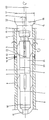
- the drilling device comprises in particular a directional drilling tool 1, designed as a navigation drilling tool in the illustrated embodiment, with a tubular outer housing 2, in which a deep hole motor 3, not illustrated in more detail, is preferably accommodated in the form of a turbine which can be driven by the drilling fluid or a Moineau motor which can be driven by the drilling fluid .
- the deep hole motor 3 drives a chisel shaft 4 emerging from the front end of the outer housing 2, which is mounted in the front part of the outer housing 2 located at the level of a front stabilizer 5 and with its axis at an angle 6 to the central axis 7 of the rear main part of the outer housing 2 of the directional drilling tool 1 is aligned.
- the rear main part of the outer housing 2 is provided with a rear stabilizer 8, and the stabilizers 5, 8 formed by stabilizer wings or ribs support the outer housing 2 of the directional drilling tool 1 on the inside of a casing tube 9.
- the outer housing 2 of the directional drilling tool 1 is connected to a drill pipe string 11 by means of a transition piece 10, which at its above-ground end, which is not shown, can be driven by drive and feed means, also not shown, and can be set in its own rotation and can be supported in a non-rotatable manner in aligned positions.
- Suitable types of drive and feed means are known to the person skilled in the art and do not require any further explanation here.
- the front end of the casing tube is designed as a part 12 which can be displaced with respect to the main part of the casing tube 9 and which is in guide engagement with a guide part 13 of a rotary drill bit 14 in the region of its front edge.
- This guide part 13 of the rotary drill bit 14 is formed by a cylindrical sealing and guide surface on which the front edge region of the front end 12 of the casing tube 9 is preferably mounted with a seal.
- the rotary drill bit 14 is fixed on the front end of the chisel shaft 4 by means of a coupling 15, which comprises notchable locking members, not shown, and can be temporarily uncoupled from the chisel shaft.
- the rotary drill bit 14 or its cutting part 16 has a nominal diameter 17 which is the same or slightly larger than the outer diameter of the tubular casing 9.
- the front end 12 of the casing tube 9, which is designed as a separately displaceable part, is connected via a pipe joint to the adjoining main part of the casing tube 9, which in the exemplary embodiment shown and is preferably designed as a cut joint 18.
- the separating cut joint is sealed by an outer circumferential seal 19.
- the pipe joint can also be formed by a flexible transition area of the casing tube 9, and the flexible transition area can in turn be a corrugated pipe section, a section made of a material with increased bending elasticity or also a section of the casing pipe 9 with an opposite one Areas of the casing tube 9 reduced section modulus.
- the angle 6 between the axis of the chisel shaft 4 and the central axis 7 of the outer tube 2 of the directional drilling tool 1 is formed by kinking the front part of the outer housing 2 located in the region of the front stabilizer 5, the kink 20 of the outer housing 2 being opposite to the drilling direction the stabilizer 5 and at the same time is arranged in or near the joint plane of the tubular joint 18 of the tubular casing 8.
- the kink angle corresponding to the angle 6 in the example shown lies in an imaginary plane running perpendicular to the plane of the drawing through the central axis 7 of the casing tube 9.
- the front end 12 of the casing tube 9 can with relative rotary movements between the front parts 5, 13 of the directional drilling tool 1 and the Jacket tube 9 follow the movements of the front part of directional drilling tool 1 and how this describes with its axis the surface line of a circular cone, the tip of which coincides with the kink 20 of the outer housing 2 of directional drilling tool 1.
- part of the drilling fluid can be supplied via a volume flow-dependent bypass valve 24 provided in the outer housing 2 downstream of the downhole motor 3 are derived in the annular space 25 between the outer housing 2 and the casing tube 9, so that only a correspondingly reduced part of the drilling fluid delivered per unit of time passes the rotary drill bit 14 and passes into the borehole.
- the directional drilling tool 1 and the casing tube 9 are rotated, the direction of rotation of the casing tube 9 and the directional drilling tool 1 being the same, but preferably being opposite.
- the slow self-rotation of the directional drilling tool 1 ensures the straight-ahead drilling process despite the kinking of the outer housing 2, an additional broaching effect being created by the eccentricity 23.
- the rotary movement of the casing tube 9, serves to reduce the resistance to the advancing movement of the casing tube 9 in the formation. Accordingly, the rotational speed of the rotary movement of the casing tube 9 can easily deviate from that of the directional drilling tool 1 and can be determined from the point of view of minimizing resistance.
- the directional drilling tool 1 is stopped by the drive and feed means and the drill pipe string in an orientation of the outer housing 2 which corresponds to the further directional course of the borehole.
- the respective position of the rotary drill bit 14 or the directional drilling tool 1 in the borehole can be determined continuously or at intervals by suitable sensors, so that the desired course of the borehole can be precisely specified by alternately stopping or rotating the directional drilling tool 1.
- the coupling 15 between the chisel shaft 4 and the rotary drill bit 14 enables the directional drilling tool 1 to be moved out of the borehole with the casing tube 9 remaining therein, e.g. for inspection and maintenance purposes.
Landscapes
- Life Sciences & Earth Sciences (AREA)
- Engineering & Computer Science (AREA)
- Geology (AREA)
- Mining & Mineral Resources (AREA)
- Physics & Mathematics (AREA)
- Environmental & Geological Engineering (AREA)
- Fluid Mechanics (AREA)
- General Life Sciences & Earth Sciences (AREA)
- Geochemistry & Mineralogy (AREA)
- Earth Drilling (AREA)
Applications Claiming Priority (2)
| Application Number | Priority Date | Filing Date | Title |
|---|---|---|---|
| DE3902868 | 1989-02-01 | ||
| DE3902868A DE3902868C1 (fr) | 1989-02-01 | 1989-02-01 |
Publications (3)
| Publication Number | Publication Date |
|---|---|
| EP0380910A2 true EP0380910A2 (fr) | 1990-08-08 |
| EP0380910A3 EP0380910A3 (fr) | 1992-05-27 |
| EP0380910B1 EP0380910B1 (fr) | 1995-03-08 |
Family
ID=6373168
Family Applications (1)
| Application Number | Title | Priority Date | Filing Date |
|---|---|---|---|
| EP90100112A Expired - Lifetime EP0380910B1 (fr) | 1989-02-01 | 1990-01-04 | Procédé et dispositif pour le forage horizontal |
Country Status (5)
| Country | Link |
|---|---|
| US (1) | US5033556A (fr) |
| EP (1) | EP0380910B1 (fr) |
| CA (1) | CA2008977A1 (fr) |
| DE (1) | DE3902868C1 (fr) |
| NO (1) | NO900457L (fr) |
Families Citing this family (14)
| Publication number | Priority date | Publication date | Assignee | Title |
|---|---|---|---|---|
| US5074366A (en) * | 1990-06-21 | 1991-12-24 | Baker Hughes Incorporated | Method and apparatus for horizontal drilling |
| US5148875A (en) * | 1990-06-21 | 1992-09-22 | Baker Hughes Incorporated | Method and apparatus for horizontal drilling |
| US5311953A (en) * | 1992-08-07 | 1994-05-17 | Baroid Technology, Inc. | Drill bit steering |
| US5386878A (en) * | 1994-04-29 | 1995-02-07 | Uti Energy Corp. | Rock boring process and apparatus |
| US5425429A (en) * | 1994-06-16 | 1995-06-20 | Thompson; Michael C. | Method and apparatus for forming lateral boreholes |
| EP0768446B1 (fr) * | 1995-10-09 | 2000-07-12 | Baker Hughes Incorporated | Procédé et outil de forage pour le forage de puits dans les formations souterraines |
| CA2235196C (fr) | 1998-04-20 | 2003-03-25 | Erez Nissim Allouche | Methode d'echantillonnage du sol a partir d'un trou de forage horizontal |
| CA2271401C (fr) * | 1999-02-23 | 2008-07-29 | Tesco Corporation | Forage avec tubage |
| HRPK20020690B3 (en) * | 2000-02-24 | 2005-06-30 | Techmo Entwicklungs- und Vertriebs GmbH ALWAG Tunnelausbau Gesellschaft m.b.H. | Device for drilling, especially percussion or rotary percussion drilling holes |
| US20090236146A1 (en) * | 2008-03-19 | 2009-09-24 | Caterpillar Inc. | Machine and method for trenchless conduit installation |
| FI20096109L (fi) * | 2009-10-28 | 2011-04-29 | Sandvik Mining & Constr Oy | Menetelmä suojarakenteen liittämiseksi syöttöpalkkiin ja kaivostoimilaitteen suojarakenne |
| RU2435925C1 (ru) * | 2010-05-11 | 2011-12-10 | Открытое акционерное общество "Всероссийский научно-исследовательский институт по осушению месторождений полезных ископаемых, защите инженерных сооружений от обводнения, специальным горным работам, геомеханике, геофизике, гидротехнике, геологии и маркшейдерскому делу" | Способ сооружения горизонтальной дренажной скважины в неустойчивых подвижных горных породах и буровой снаряд для его осуществления |
| DE102012217822A1 (de) * | 2012-09-28 | 2014-04-03 | Bohlen & Doyen Bauunternehmung Gmbh | Vorrichtung und Verfahren zur Verlegung einer Rohrleitung in einem Bohrloch |
| CN106014258B (zh) * | 2016-05-18 | 2019-03-15 | 中煤科工集团西安研究院有限公司 | 煤矿井下同心跟管定向钻进装置及其施工方法 |
Family Cites Families (8)
| Publication number | Priority date | Publication date | Assignee | Title |
|---|---|---|---|---|
| US4176985A (en) * | 1975-07-14 | 1979-12-04 | Reading And Bates Construction Co. | System and method for installing production casings |
| US4121673A (en) * | 1976-11-10 | 1978-10-24 | Martin Dee Cherrington | Drilling and installation system |
| US4492276A (en) * | 1982-11-17 | 1985-01-08 | Shell Oil Company | Down-hole drilling motor and method for directional drilling of boreholes |
| DE3423465C1 (de) * | 1984-06-26 | 1985-05-02 | Norton Christensen, Inc., Salt Lake City, Utah | Vorrichtungen zum wahlweisen Geradeaus- oder Richtungsbohren in unterirdische Gesteinsformationen |
| US4629012A (en) * | 1985-07-08 | 1986-12-16 | Atlantic Richfield Company | Drainhole drilling assembly |
| DE3534662A1 (de) * | 1985-09-28 | 1987-04-09 | Huneke Karl | Lenkbarer vortriebskopf einer vorrichtung zum herstellen einer durchdringung im erdboden |
| US4667751A (en) * | 1985-10-11 | 1987-05-26 | Smith International, Inc. | System and method for controlled directional drilling |
| DE3839760C1 (en) * | 1988-11-25 | 1990-01-18 | Gewerkschaft Walter Ag | Double rotary drilling apparatus for making directionally accurate bores, in particular horizontal bores |
-
1989
- 1989-02-01 DE DE3902868A patent/DE3902868C1/de not_active Expired - Lifetime
-
1990
- 1990-01-04 EP EP90100112A patent/EP0380910B1/fr not_active Expired - Lifetime
- 1990-01-31 CA CA002008977A patent/CA2008977A1/fr not_active Abandoned
- 1990-01-31 US US07/472,725 patent/US5033556A/en not_active Expired - Fee Related
- 1990-01-31 NO NO90900457A patent/NO900457L/no unknown
Also Published As
| Publication number | Publication date |
|---|---|
| EP0380910B1 (fr) | 1995-03-08 |
| CA2008977A1 (fr) | 1990-08-01 |
| EP0380910A3 (fr) | 1992-05-27 |
| NO900457D0 (no) | 1990-01-31 |
| NO900457L (no) | 1990-08-02 |
| DE3902868C1 (fr) | 1990-06-07 |
| US5033556A (en) | 1991-07-23 |
Similar Documents
| Publication | Publication Date | Title |
|---|---|---|
| EP3081737B1 (fr) | Appareil de forage destine a pratiquer un forage tube et procede de fonctionnement d'un appareil de forage | |
| DE2540590C2 (de) | Verfahren zur Herstellung einer bogenförmigen Bohrung unterhalb eines Hindernisses | |
| DE69605779T2 (de) | Von der öberfläche aus kontrolliertes richtbohrwerkzeug | |
| EP0380910B1 (fr) | Procédé et dispositif pour le forage horizontal | |
| DE3035876C2 (fr) | ||
| EP0768446B1 (fr) | Procédé et outil de forage pour le forage de puits dans les formations souterraines | |
| DE19612902C2 (de) | Verfahren zum Richtungsbohren und eine Vorrichtung zur Durchführung des Verfahrens | |
| DE3902869C1 (fr) | ||
| DE60218282T2 (de) | Aufweitvorrichtung | |
| DE19725996A1 (de) | Wasserbohrlochsystem | |
| EP0204694A1 (fr) | Dispositif pour effectuer des travaux d'amelioration sur une canalisation endommagee qui n'est plus accessible. | |
| EP0293584B1 (fr) | Dispositif de forage pour méthode de forage par injection à haute pression | |
| EP0744526B1 (fr) | Méthode pour contrôler la direction d'un outil de forage | |
| DE2162314A1 (de) | Erdbohrverfahren und Erdbohrmaschine | |
| EP0578034B1 (fr) | Procédé et dispositif pour le forage d'un trou dans le sol | |
| DE69119402T2 (de) | Im bohrloch zu gebrauchendes bohrwerkzeug zum bohren vor einer verrohrung | |
| EP1491716B1 (fr) | Méthode de forage et outil de forage humide | |
| EP2900895B1 (fr) | Dispositif et procédé de pose d'une canalisation dans un trou de forage | |
| DE2306462A1 (de) | Dreh-bohr-vorrichtung nach dem gegenstrom-system | |
| DE4138356A1 (de) | Bohrvorrichtung fuer den tiefbau sowie verfahren zum herstellen von stabilisierenden saeulen oder aehnlichen gebilden in erdreich | |
| AT413422B (de) | Verfahren und vorrichtung zum vermessen eines bohrlochs | |
| EP0837190A2 (fr) | Dispositif et procédé pour la réalisation controlée de pieux et parois moulées dans le sol | |
| DE3839760C1 (en) | Double rotary drilling apparatus for making directionally accurate bores, in particular horizontal bores | |
| DE1942857C3 (de) | Erdbohrmaschine zum Herstellen von Bodenschlitzen | |
| DE2642014A1 (de) | Anschlusstueck fuer bohrmeissel |
Legal Events
| Date | Code | Title | Description |
|---|---|---|---|
| PUAI | Public reference made under article 153(3) epc to a published international application that has entered the european phase |
Free format text: ORIGINAL CODE: 0009012 |
|
| AK | Designated contracting states |
Kind code of ref document: A2 Designated state(s): BE FR GB NL |
|
| PUAL | Search report despatched |
Free format text: ORIGINAL CODE: 0009013 |
|
| AK | Designated contracting states |
Kind code of ref document: A3 Designated state(s): BE FR GB NL |
|
| 17P | Request for examination filed |
Effective date: 19920827 |
|
| RAP1 | Party data changed (applicant data changed or rights of an application transferred) |
Owner name: EASTMAN TELECO COMPANY |
|
| 17Q | First examination report despatched |
Effective date: 19931014 |
|
| GRAA | (expected) grant |
Free format text: ORIGINAL CODE: 0009210 |
|
| AK | Designated contracting states |
Kind code of ref document: B1 Designated state(s): BE FR GB NL |
|
| RBV | Designated contracting states (corrected) |
Designated state(s): FR GB NL |
|
| ET | Fr: translation filed | ||
| GBT | Gb: translation of ep patent filed (gb section 77(6)(a)/1977) |
Effective date: 19950324 |
|
| PGFP | Annual fee paid to national office [announced via postgrant information from national office to epo] |
Ref country code: FR Payment date: 19951213 Year of fee payment: 7 |
|
| PGFP | Annual fee paid to national office [announced via postgrant information from national office to epo] |
Ref country code: GB Payment date: 19951228 Year of fee payment: 7 |
|
| PLBE | No opposition filed within time limit |
Free format text: ORIGINAL CODE: 0009261 |
|
| STAA | Information on the status of an ep patent application or granted ep patent |
Free format text: STATUS: NO OPPOSITION FILED WITHIN TIME LIMIT |
|
| 26N | No opposition filed | ||
| PG25 | Lapsed in a contracting state [announced via postgrant information from national office to epo] |
Ref country code: GB Effective date: 19970104 |
|
| REG | Reference to a national code |
Ref country code: GB Ref legal event code: 732E |
|
| GBPC | Gb: european patent ceased through non-payment of renewal fee |
Effective date: 19970104 |
|
| PG25 | Lapsed in a contracting state [announced via postgrant information from national office to epo] |
Ref country code: FR Effective date: 19970930 |
|
| NLS | Nl: assignments of ep-patents |
Owner name: MICON MINING AND CONSTRUCTION PRODUCTS,GMBH & CO.K |
|
| NLT1 | Nl: modifications of names registered in virtue of documents presented to the patent office pursuant to art. 16 a, paragraph 1 |
Owner name: BAKER HUGHES OILFIELD OPERATIONS, INC.;BAKER HUGHE |
|
| REG | Reference to a national code |
Ref country code: FR Ref legal event code: ST |
|
| PGFP | Annual fee paid to national office [announced via postgrant information from national office to epo] |
Ref country code: NL Payment date: 19980130 Year of fee payment: 9 |
|
| PG25 | Lapsed in a contracting state [announced via postgrant information from national office to epo] |
Ref country code: NL Free format text: LAPSE BECAUSE OF NON-PAYMENT OF DUE FEES Effective date: 19990801 |