EP0380916A1 - Cheville pour plaque creuse - Google Patents
Cheville pour plaque creuse Download PDFInfo
- Publication number
- EP0380916A1 EP0380916A1 EP90100203A EP90100203A EP0380916A1 EP 0380916 A1 EP0380916 A1 EP 0380916A1 EP 90100203 A EP90100203 A EP 90100203A EP 90100203 A EP90100203 A EP 90100203A EP 0380916 A1 EP0380916 A1 EP 0380916A1
- Authority
- EP
- European Patent Office
- Prior art keywords
- sleeve
- hollow plate
- bolt
- borehole
- dowel
- Prior art date
- Legal status (The legal status is an assumption and is not a legal conclusion. Google has not performed a legal analysis and makes no representation as to the accuracy of the status listed.)
- Withdrawn
Links
- 238000000034 method Methods 0.000 abstract description 7
- 238000004873 anchoring Methods 0.000 description 5
- 238000009434 installation Methods 0.000 description 2
Images

Classifications
-
- F—MECHANICAL ENGINEERING; LIGHTING; HEATING; WEAPONS; BLASTING
- F16—ENGINEERING ELEMENTS AND UNITS; GENERAL MEASURES FOR PRODUCING AND MAINTAINING EFFECTIVE FUNCTIONING OF MACHINES OR INSTALLATIONS; THERMAL INSULATION IN GENERAL
- F16B—DEVICES FOR FASTENING OR SECURING CONSTRUCTIONAL ELEMENTS OR MACHINE PARTS TOGETHER, e.g. NAILS, BOLTS, CIRCLIPS, CLAMPS, CLIPS OR WEDGES; JOINTS OR JOINTING
- F16B13/00—Dowels or other devices fastened in walls or the like by inserting them in holes made therein for that purpose
- F16B13/001—Dowels or other devices fastened in walls or the like by inserting them in holes made therein for that purpose with means for preventing rotation of the dowel
-
- F—MECHANICAL ENGINEERING; LIGHTING; HEATING; WEAPONS; BLASTING
- F16—ENGINEERING ELEMENTS AND UNITS; GENERAL MEASURES FOR PRODUCING AND MAINTAINING EFFECTIVE FUNCTIONING OF MACHINES OR INSTALLATIONS; THERMAL INSULATION IN GENERAL
- F16B—DEVICES FOR FASTENING OR SECURING CONSTRUCTIONAL ELEMENTS OR MACHINE PARTS TOGETHER, e.g. NAILS, BOLTS, CIRCLIPS, CLAMPS, CLIPS OR WEDGES; JOINTS OR JOINTING
- F16B13/00—Dowels or other devices fastened in walls or the like by inserting them in holes made therein for that purpose
- F16B13/04—Dowels or other devices fastened in walls or the like by inserting them in holes made therein for that purpose with parts gripping in the hole or behind the reverse side of the wall after inserting from the front
- F16B13/06—Dowels or other devices fastened in walls or the like by inserting them in holes made therein for that purpose with parts gripping in the hole or behind the reverse side of the wall after inserting from the front combined with expanding sleeve
- F16B13/063—Dowels or other devices fastened in walls or the like by inserting them in holes made therein for that purpose with parts gripping in the hole or behind the reverse side of the wall after inserting from the front combined with expanding sleeve by the use of an expander
- F16B13/065—Dowels or other devices fastened in walls or the like by inserting them in holes made therein for that purpose with parts gripping in the hole or behind the reverse side of the wall after inserting from the front combined with expanding sleeve by the use of an expander fastened by extracting the screw, nail or the like
-
- F—MECHANICAL ENGINEERING; LIGHTING; HEATING; WEAPONS; BLASTING
- F16—ENGINEERING ELEMENTS AND UNITS; GENERAL MEASURES FOR PRODUCING AND MAINTAINING EFFECTIVE FUNCTIONING OF MACHINES OR INSTALLATIONS; THERMAL INSULATION IN GENERAL
- F16B—DEVICES FOR FASTENING OR SECURING CONSTRUCTIONAL ELEMENTS OR MACHINE PARTS TOGETHER, e.g. NAILS, BOLTS, CIRCLIPS, CLAMPS, CLIPS OR WEDGES; JOINTS OR JOINTING
- F16B13/00—Dowels or other devices fastened in walls or the like by inserting them in holes made therein for that purpose
- F16B13/04—Dowels or other devices fastened in walls or the like by inserting them in holes made therein for that purpose with parts gripping in the hole or behind the reverse side of the wall after inserting from the front
- F16B13/08—Dowels or other devices fastened in walls or the like by inserting them in holes made therein for that purpose with parts gripping in the hole or behind the reverse side of the wall after inserting from the front with separate or non-separate gripping parts moved into their final position in relation to the body of the device without further manual operation
-
- F—MECHANICAL ENGINEERING; LIGHTING; HEATING; WEAPONS; BLASTING
- F16—ENGINEERING ELEMENTS AND UNITS; GENERAL MEASURES FOR PRODUCING AND MAINTAINING EFFECTIVE FUNCTIONING OF MACHINES OR INSTALLATIONS; THERMAL INSULATION IN GENERAL
- F16B—DEVICES FOR FASTENING OR SECURING CONSTRUCTIONAL ELEMENTS OR MACHINE PARTS TOGETHER, e.g. NAILS, BOLTS, CIRCLIPS, CLAMPS, CLIPS OR WEDGES; JOINTS OR JOINTING
- F16B13/00—Dowels or other devices fastened in walls or the like by inserting them in holes made therein for that purpose
- F16B2013/007—Dowels or other devices fastened in walls or the like by inserting them in holes made therein for that purpose to be fastened in undercut holes
Definitions
- the invention relates to a hollow board anchor according to the preamble of the main claim.
- Fastening elements which are intended for use in boreholes in masonry and which have a conical undercut.
- the positive anchoring of these fasteners is effected in that a cone bolt with the sleeve is driven into the borehole and the sleeve, when the cone bolt strikes the base of the borehole, spreads with its spreading area in the region of the cone located on the bolt and partly via the cone into the borehole is struck.
- the conical bolt is finally brought back into the sleeve until the sleeve has been expanded in a positive manner with the undercut borehole in its expansion area.
- a disadvantage of this type of anchoring of fasteners is that, in particular, between the phase of assembly of the sleeve being fully driven in and the phase of its expansion by a nut turned with a screw, a securing device against the fastening element falling out is not provided.
- this proves to be necessary particularly in the case of vertically running boreholes in ceilings etc.
- the invention has for its object to provide a hollow board anchor that is easy to assemble and has a security against falling out of the anchor during the assembly process.
- the anti-rotation lock that can be screwed onto the end face of the sleeve via the conical bolt ensures that the dowel can be anchored regardless of whether the fastening is located in a cavity area or in a web area. This prevents the bolt from rotating in the sleeve provided with an expansion area during the screwing process that takes place during the assembly.
- the elongated longitudinal ribs located on the outer surface of the tubular part of the anti-rotation device secure the sleeve from possible turning during the screwing process.
- the hollow plate dowel is preferably made of elastic plastic, whereby tolerance compensation is achieved during the drive-in process. To avoid a free-standing installation, this contributes in particular to the fact that the anti-rotation device is partially squeezed due to its nature during the impact.
- the end of the anti-rotation device flush with the subsurface in the area of the borehole is also favored in that the tubular part has a smaller diameter of the bore only in its central area, i.e. in this area the tube wall is reinforced. This enables a slight pinching at the end edges of the tubular part.
- the hollow plate dowel shown in Figure 1 consists of a bolt 1 at the end of which a cone 2 is formed. In its upper area, the bolt 1 has an external thread 3.
- the rotation lock provided with longitudinal ribs is screwed onto the cylindrical sleeve 5 of the dowel via the area of the bolt 1 equipped with an external thread.
- the hollow plate dowel thus obtained is hammered into a pre-drilled borehole 6 provided with an undercut.
- the sleeve is spread in its spreading area 7 over the cone 2 of the bolt 1 by further striking movements.
- the spreading region 7 is spread openly in the undercut borehole 6 by means of a screwdriver or socket wrench attached to the nut 9 by screwing in.
- the rotation lock 4 prevents rotation with the bolt 1 during assembly, since the rotation lock 4 has an internal thread that engages in the external thread 3 of the bolt 1.
- the hollow plate dowel shown in FIG. 2 shows the bolt provided with an external thread 3 and completely drawn into the expansion area 7 with the cone located thereon.
- the anti-rotation device 4 was hammered in flush with the area surrounding the borehole 11 during the assembly process. Since, in the present case, the dowel inserted into the borehole meets a cavity region 12 at the bottom of the borehole, there is a risk that when a nut 9 is screwed in, the bolt located in the sleeve 5 will also rotate, thus preventing a complete expansion of the expansion region 7 and thereby jeopardizing firm anchoring . Rotation during assembly is prevented by the anti-rotation device 4 provided with an internal thread, and thus an expansion of the expansion area 7 is ensured for firm anchoring.
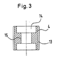
- the anti-rotation device 4 shown in cross section in FIG. 3 has longitudinal ribs 13 on its outer surface which firmly anchor the anti-rotation device in the borehole.
- the bore 14 of the tubular part of the rotation lock 4 has a smaller diameter in its central region.
- the rotation lock is equipped with an internal thread 15, which enables the rotation lock 4 to be screwed on via the bolt provided with an external thread.
Landscapes
- Engineering & Computer Science (AREA)
- General Engineering & Computer Science (AREA)
- Mechanical Engineering (AREA)
- Joining Of Building Structures In Genera (AREA)
- Dowels (AREA)
Applications Claiming Priority (2)
| Application Number | Priority Date | Filing Date | Title |
|---|---|---|---|
| DE8901067U | 1989-02-01 | ||
| DE8901067U DE8901067U1 (de) | 1989-02-01 | 1989-02-01 | Hohlplattendübel |
Publications (1)
| Publication Number | Publication Date |
|---|---|
| EP0380916A1 true EP0380916A1 (fr) | 1990-08-08 |
Family
ID=6835565
Family Applications (1)
| Application Number | Title | Priority Date | Filing Date |
|---|---|---|---|
| EP90100203A Withdrawn EP0380916A1 (fr) | 1989-02-01 | 1990-01-05 | Cheville pour plaque creuse |
Country Status (5)
| Country | Link |
|---|---|
| US (1) | US4973207A (fr) |
| EP (1) | EP0380916A1 (fr) |
| JP (1) | JPH02225811A (fr) |
| BR (1) | BR9000420A (fr) |
| DE (1) | DE8901067U1 (fr) |
Families Citing this family (5)
| Publication number | Priority date | Publication date | Assignee | Title |
|---|---|---|---|---|
| WO1999066990A1 (fr) * | 1998-06-25 | 1999-12-29 | Peter Schild | Crochet d'escalade |
| DE102006049952B4 (de) * | 2006-10-19 | 2011-02-10 | Zimmer, Günther | Dübel für Deckplattenhintergriff und Deckplatteneinspreizung |
| WO2008046410A1 (fr) * | 2006-10-19 | 2008-04-24 | Zimmer Guenther | Cheville à expansion pour insertion dans une plaque de recouvrement |
| DE102006049954B4 (de) * | 2006-10-19 | 2011-01-20 | Zimmer, Günther | Dübel für Deckplattenhinter- und eingriff |
| CN101761532B (zh) * | 2010-02-09 | 2012-05-30 | 沈英 | 人造空心板材的锚栓连接装置及其连接方法 |
Citations (3)
| Publication number | Priority date | Publication date | Assignee | Title |
|---|---|---|---|---|
| DE2758091A1 (de) * | 1977-12-24 | 1979-07-05 | Heinrich Liebig | Formschluessig setzbarer duebel |
| DE2947751A1 (de) * | 1979-11-27 | 1981-08-06 | M.Meisinger KG, 8890 Aichach | Hohlraumduebel |
| DE3012498A1 (de) * | 1980-03-31 | 1981-10-08 | Hilti AG, 9494 Schaan | Spreizduebel |
Family Cites Families (10)
| Publication number | Priority date | Publication date | Assignee | Title |
|---|---|---|---|---|
| DE2311298B1 (de) * | 1973-03-07 | 1974-08-08 | Artur Fischer | Befestigungselement zur Verankerung in Betonbauwerksteilen |
| DE2401243B2 (de) * | 1974-01-11 | 1975-11-13 | Artur 7241 Tumlingen Fischer | Befestigungselement zur Befestigung von Bauteilen an einer Wand oder dgl |
| DE2745805A1 (de) * | 1977-10-12 | 1979-04-19 | Heinz Ehrhardt | Vorrichtung zur allgemeinen verankerung klemmnagel |
| DE2815998A1 (de) * | 1978-04-13 | 1979-10-18 | Fischer Artur Dr H C | Befestigungselement zur befestigung von bauteilen an einer wand o.dgl. |
| JPS552264U (fr) * | 1979-04-24 | 1980-01-09 | ||
| JPS6018695Y2 (ja) * | 1979-08-27 | 1985-06-06 | 東邦ガス工業株式会社 | ウオ−タ−バルブ |
| DE3121198A1 (de) * | 1981-05-27 | 1982-12-23 | Hilti AG, 9494 Schaan | Spreizduebel |
| DE3420375C2 (de) * | 1984-06-01 | 1987-03-19 | Fischer, Artur, Dr.H.C., 7244 Waldachtal | Dübel |
| DE3707510A1 (de) * | 1987-02-21 | 1988-09-01 | Fischer Artur Werke Gmbh | Duebel mit spreizhuelse |
| US4789284A (en) * | 1987-11-05 | 1988-12-06 | White Scott A | Self-cutting expansion anchor |
-
1989
- 1989-02-01 DE DE8901067U patent/DE8901067U1/de not_active Expired - Lifetime
-
1990
- 1990-01-05 EP EP90100203A patent/EP0380916A1/fr not_active Withdrawn
- 1990-01-29 JP JP2016310A patent/JPH02225811A/ja active Pending
- 1990-01-29 US US07/472,205 patent/US4973207A/en not_active Expired - Fee Related
- 1990-01-31 BR BR909000420A patent/BR9000420A/pt unknown
Patent Citations (3)
| Publication number | Priority date | Publication date | Assignee | Title |
|---|---|---|---|---|
| DE2758091A1 (de) * | 1977-12-24 | 1979-07-05 | Heinrich Liebig | Formschluessig setzbarer duebel |
| DE2947751A1 (de) * | 1979-11-27 | 1981-08-06 | M.Meisinger KG, 8890 Aichach | Hohlraumduebel |
| DE3012498A1 (de) * | 1980-03-31 | 1981-10-08 | Hilti AG, 9494 Schaan | Spreizduebel |
Also Published As
| Publication number | Publication date |
|---|---|
| US4973207A (en) | 1990-11-27 |
| BR9000420A (pt) | 1991-01-15 |
| DE8901067U1 (de) | 1990-07-05 |
| JPH02225811A (ja) | 1990-09-07 |
Similar Documents
| Publication | Publication Date | Title |
|---|---|---|
| DE69333415T2 (de) | Verankerungssystem zum aussenseitigen befestigen von material einem gebäude | |
| EP0628384B1 (fr) | Procédé pour la mise en place des éléments de fixation | |
| DE10041299B4 (de) | Befestigungssystem | |
| EP0336183B1 (fr) | Dispositif de fixation d'une partie filetée dans un trou à chambrage | |
| EP0314912B1 (fr) | Cheville d'expansion pour l'ancrage dans des trous ayant une retassure | |
| EP0297228A1 (fr) | Des chevilles à expansion, à ancrage dans des trous forés de forme conique s'évasant vers l'intérieur | |
| DE102004064114B4 (de) | Befestigungselement für Dämmstoffplatten | |
| DE3715420A1 (de) | Distanzschraube | |
| EP0019782A2 (fr) | Cheville métallique creuse | |
| DE19642914C2 (de) | Dübel | |
| EP0380916A1 (fr) | Cheville pour plaque creuse | |
| DE3333055C2 (de) | Vorrichtung zum Befestigen von Latten | |
| DE3502607A1 (de) | Anker, insbesondere lastabhaengiger duebel | |
| DE8321395U1 (de) | Langdübeleinheit | |
| DE3427608A1 (de) | Unterkonstruktionsausgleichsschraube | |
| CH642723A5 (en) | Expanding dowel for attaching cladding elements with a gap | |
| DE3020907C2 (fr) | ||
| DE19537000C1 (de) | Verfahren zur einstellbaren Befestigung von Latten, Profilschienen, Platten oder dergleichen an einem festen Untergrund und Befestigungselement zur Durchführung des Verfahrens | |
| DE4215435C2 (de) | Schalldämmende Verbindung | |
| EP0250783B1 (fr) | Cheville à expansion | |
| EP0034346A1 (fr) | Dispositif de fixation pour fixer des revêtements, listeaux ou analogues sur un mur au moyen d'une cheville à tête de serrage en matière plastique | |
| EP0286706A1 (fr) | Cheville | |
| DE1650962A1 (de) | Duebel,insbesondere zum Befestigen von Bauteilen am Mauerwerk | |
| DE3820759A1 (de) | Spreizduebel zum einschlagen in ein bohrloch mit hinterschneidung | |
| WO1997041325A1 (fr) | Dispositif d'ajustage pour element de construction a inserer dans une ouverture de batiment, tel que cadre de fenetre ou de porte |
Legal Events
| Date | Code | Title | Description |
|---|---|---|---|
| PUAI | Public reference made under article 153(3) epc to a published international application that has entered the european phase |
Free format text: ORIGINAL CODE: 0009012 |
|
| AK | Designated contracting states |
Kind code of ref document: A1 Designated state(s): AT BE CH DE DK ES FR GB IT LI NL |
|
| 17P | Request for examination filed |
Effective date: 19901213 |
|
| 17Q | First examination report despatched |
Effective date: 19910913 |
|
| STAA | Information on the status of an ep patent application or granted ep patent |
Free format text: STATUS: THE APPLICATION IS DEEMED TO BE WITHDRAWN |
|
| 18D | Application deemed to be withdrawn |
Effective date: 19920124 |