EP0380954A2 - Dispositif d'extraction de copeaux pour raboteuse - Google Patents
Dispositif d'extraction de copeaux pour raboteuse Download PDFInfo
- Publication number
- EP0380954A2 EP0380954A2 EP90100798A EP90100798A EP0380954A2 EP 0380954 A2 EP0380954 A2 EP 0380954A2 EP 90100798 A EP90100798 A EP 90100798A EP 90100798 A EP90100798 A EP 90100798A EP 0380954 A2 EP0380954 A2 EP 0380954A2
- Authority
- EP
- European Patent Office
- Prior art keywords
- compressed air
- circuit
- chip
- channel
- valve
- Prior art date
- Legal status (The legal status is an assumption and is not a legal conclusion. Google has not performed a legal analysis and makes no representation as to the accuracy of the status listed.)
- Withdrawn
Links
- 239000002023 wood Substances 0.000 abstract description 3
- 238000009825 accumulation Methods 0.000 description 1
- 230000008021 deposition Effects 0.000 description 1
- 238000003754 machining Methods 0.000 description 1
Images
Classifications
-
- B—PERFORMING OPERATIONS; TRANSPORTING
- B23—MACHINE TOOLS; METAL-WORKING NOT OTHERWISE PROVIDED FOR
- B23Q—DETAILS, COMPONENTS, OR ACCESSORIES FOR MACHINE TOOLS, e.g. ARRANGEMENTS FOR COPYING OR CONTROLLING; MACHINE TOOLS IN GENERAL CHARACTERISED BY THE CONSTRUCTION OF PARTICULAR DETAILS OR COMPONENTS; COMBINATIONS OR ASSOCIATIONS OF METAL-WORKING MACHINES, NOT DIRECTED TO A PARTICULAR RESULT
- B23Q11/00—Accessories fitted to machine tools for keeping tools or parts of the machine in good working condition or for cooling work; Safety devices specially combined with or arranged in, or specially adapted for use in connection with, machine tools
- B23Q11/0042—Devices for removing chips
- B23Q11/005—Devices for removing chips by blowing
-
- B—PERFORMING OPERATIONS; TRANSPORTING
- B27—WORKING OR PRESERVING WOOD OR SIMILAR MATERIAL; NAILING OR STAPLING MACHINES IN GENERAL
- B27C—PLANING, DRILLING, MILLING, TURNING OR UNIVERSAL MACHINES FOR WOOD OR SIMILAR MATERIAL
- B27C1/00—Machines for producing flat surfaces, e.g. by rotary cutters; Equipment therefor
- B27C1/14—Other details or accessories
-
- B—PERFORMING OPERATIONS; TRANSPORTING
- B27—WORKING OR PRESERVING WOOD OR SIMILAR MATERIAL; NAILING OR STAPLING MACHINES IN GENERAL
- B27G—ACCESSORY MACHINES OR APPARATUS FOR WORKING WOOD OR SIMILAR MATERIALS; TOOLS FOR WORKING WOOD OR SIMILAR MATERIALS; SAFETY DEVICES FOR WOOD WORKING MACHINES OR TOOLS
- B27G3/00—Arrangements for removing bark-zones, chips, waste, or dust, specially designed for use in connection with wood-working machine or in wood-working plants
Definitions
- the invention relates to a device for chip evacuation on planing machines or similar chip-producing woodworking machines, with a chip discharge channel that begins near the tool, in particular the planer knife, and with a compressed air supply line to the channel.
- chip-producing woodworking machines are made by a rotating knife shaft or chips generated by other tools that are to be passed through a chip channel.
- the chips are generally transported by the compressed air flow generated by the rotating tool.
- suction devices that convey the chips further, for example to a separating device or the like.
- the invention is based on a device of the type specified at the beginning and suggests that a controllable valve is arranged in the compressed air line, and that a circuit is also provided which continuously opens the valve briefly.
- the chips deposited can be conveyed further by pulse-like, short bursts of compressed air, so that an accumulation and deposition in the knife area is excluded. Due to the pulsed supply of compressed air, the total consumption of compressed air remains low, even if the full available pressure of usually 6 bar is used for a short time.
- the compressed air device which is installed in the vicinity of such machines, is generally sufficient for the compressed air supply.
- the compressed air supply line opens into the chip discharge channel approximately parallel to the axis of the planing knife. It has been found that it is not necessary to introduce the compressed air flow in the discharge direction in order to achieve the desired effect. As a result, complicated channels near the start of the drainage channel can be avoided. A simple, right-angled introduction to the main flow direction is sufficient. The chips are forwarded in the desired direction.
- the circuit for controlling the valve can be controlled, for example, by the drive of the planing machine. In many cases, however, it is advisable to provide programmable control of the circuit, it being possible, for example, to use the work program according to which the planing machine carries out its machining operations anyway.
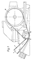
- the planer which is shown in Fig. 1, has a known design.
- the motor 8 drives the planer knife 6 via a belt 9, which rotates about the axis 5 in the direction of the arrow 10.
- the frame in which the planer knife is mounted surrounds the chip discharge channel 7, which begins at the planer knife 6.
- the walls of this channel are designated 11.
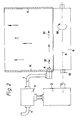
- the compressed air supply line 4 is arranged in a side wall of the channel and emits a pulsed compressed air flow in the direction of the arrows 12.
- the compressed air line is labeled 1.
- a valve 1 is installed, which is shown only schematically in the drawing and which can have any configuration. In particular, it can be an electromagnetically operated valve. However, the valve can also be designed in such a way that, due to its design, it automatically performs opening and closing movements in order to ensure the pulsed delivery of compressed air at the compressed air supply line 4.
- a switch housing which accommodates the circuit 3, which is not shown in detail.
- the design of the circuit is simple. It is only a matter of giving short switching pulses at intervals of a few seconds which briefly open valve 2 and then close it again.
- the circuit 3 can be driven, for example, by the shaft 13 of the planing knife 6. However, the circuit can also be controlled by other means, for example by a program.
Landscapes
- Life Sciences & Earth Sciences (AREA)
- Engineering & Computer Science (AREA)
- Mechanical Engineering (AREA)
- Wood Science & Technology (AREA)
- Forests & Forestry (AREA)
- Milling, Drilling, And Turning Of Wood (AREA)
- Paper (AREA)
- Fluid-Pressure Circuits (AREA)
Applications Claiming Priority (2)
| Application Number | Priority Date | Filing Date | Title |
|---|---|---|---|
| DE8901092U DE8901092U1 (de) | 1989-02-01 | 1989-02-01 | Vorrichtung zur Späneableitung an Hobelmaschinen |
| DE8901092U | 1989-02-01 |
Publications (2)
| Publication Number | Publication Date |
|---|---|
| EP0380954A2 true EP0380954A2 (fr) | 1990-08-08 |
| EP0380954A3 EP0380954A3 (fr) | 1991-08-07 |
Family
ID=6835579
Family Applications (1)
| Application Number | Title | Priority Date | Filing Date |
|---|---|---|---|
| EP19900100798 Withdrawn EP0380954A3 (fr) | 1989-02-01 | 1990-01-16 | Dispositif d'extraction de copeaux pour raboteuse |
Country Status (2)
| Country | Link |
|---|---|
| EP (1) | EP0380954A3 (fr) |
| DE (1) | DE8901092U1 (fr) |
Cited By (2)
| Publication number | Priority date | Publication date | Assignee | Title |
|---|---|---|---|---|
| EP1004413A1 (fr) * | 1998-11-19 | 2000-05-31 | Hubert Fritz | Procédé et installation pour la production de copeaux de bois imprégnés |
| CN108214686A (zh) * | 2018-01-09 | 2018-06-29 | 张振远 | 一种带木屑收集功能的木刨 |
Families Citing this family (2)
| Publication number | Priority date | Publication date | Assignee | Title |
|---|---|---|---|---|
| DE8901092U1 (de) * | 1989-02-01 | 1989-03-30 | Hundegger, Hans, 8941 Hawangen | Vorrichtung zur Späneableitung an Hobelmaschinen |
| DE102022115459B4 (de) * | 2022-06-21 | 2024-08-08 | Schunk Electronic Solutions Gmbh | Verfahren zum Absaugen von Partikeln, insbesondere beim Heraustrennen von einzelnen Leiterplatten aus einem Leiterkartennutzen, Absaugeinrichtung, Absaugsystem und Trennmaschine |
Family Cites Families (5)
| Publication number | Priority date | Publication date | Assignee | Title |
|---|---|---|---|---|
| US2706432A (en) * | 1951-07-27 | 1955-04-19 | Giddings & Lewis | Chip conveyor for milling machine |
| GB724421A (en) * | 1952-02-25 | 1955-02-23 | Glenn L Martin Co | Chip removing and lubricating device for a machine tool |
| DE1032060B (de) * | 1955-04-27 | 1958-06-12 | Herlan & Co | Mehrspindelautomat zur Bearbeitung von Tuben und aehnlichen fliessgepressten Werkstuecken |
| GB8523854D0 (en) * | 1985-09-27 | 1985-10-30 | Black & Decker Inc | Power tools |
| DE8901092U1 (de) * | 1989-02-01 | 1989-03-30 | Hundegger, Hans, 8941 Hawangen | Vorrichtung zur Späneableitung an Hobelmaschinen |
-
1989
- 1989-02-01 DE DE8901092U patent/DE8901092U1/de not_active Expired
-
1990
- 1990-01-16 EP EP19900100798 patent/EP0380954A3/fr not_active Withdrawn
Cited By (2)
| Publication number | Priority date | Publication date | Assignee | Title |
|---|---|---|---|---|
| EP1004413A1 (fr) * | 1998-11-19 | 2000-05-31 | Hubert Fritz | Procédé et installation pour la production de copeaux de bois imprégnés |
| CN108214686A (zh) * | 2018-01-09 | 2018-06-29 | 张振远 | 一种带木屑收集功能的木刨 |
Also Published As
| Publication number | Publication date |
|---|---|
| DE8901092U1 (de) | 1989-03-30 |
| EP0380954A3 (fr) | 1991-08-07 |
Similar Documents
| Publication | Publication Date | Title |
|---|---|---|
| DE69515632T2 (de) | Dentales behandlungssytem | |
| DE69303598T2 (de) | Rotierender schmirgelstreifen mit absaugung durch unterdruck, in drei stufen, von so erzeugtem staub | |
| DE2516473A1 (de) | Zahnaerztliche spritzvorrichtung | |
| DE3406728A1 (de) | Handhobelmaschine | |
| DE60208557T2 (de) | Schleifblatt mit schlitzen zum staubsaugen, vorrichtung zur endbearbeitung von oberflächen und schleifblatthalterung | |
| DE3542466A1 (de) | Mittels elektromotor angetriebener handhobel | |
| EP1136181A2 (fr) | Dispositif de polissage actionné à une main | |
| DE2366276C3 (de) | Aufnahmevorrichtung für das Mahlgut einer Mühle für den Haushalt und kleinere Gewerbebetriebe | |
| DE8901092U1 (de) | Vorrichtung zur Späneableitung an Hobelmaschinen | |
| DE3727441A1 (de) | Dental-sandstrahler mit pneumatisch gesteuerter sandaufbereitungseinheit | |
| DE19505302C2 (de) | Absaugvorrichtung, insbesondere für Dentallabor-Arbeitsplätze | |
| DE3801038A1 (de) | Verfahren zum abbremsen der geschwindigkeit von in einem pneumatischen transportsystem transportierten gegenstaenden und vorrichtung zum durchfuehren des verfahrens | |
| DE1432358A1 (de) | Verfahren und Vorrichtung zum Zufuehren von Gefaessen zu einer Flaschenreinigungsmaschine oder zu einem Pasteurisierapparat oder zu einer Flascheneinpackmaschine od.dgl. | |
| WO2010040441A1 (fr) | Appareil de projection | |
| DE7121112U (de) | Vorrichtung zur Desinfektion des Absaug Schlauches von dentalen Nebelabsauganlagen | |
| DE2542177B2 (de) | Hydraulisch-pneumatische Steuervorrichtung zur Steuerung des Mediumflusses bei zahnärztlichen Handstücken | |
| DE2036656A1 (fr) | ||
| DE3215560C2 (de) | Einrichtung zum Versprühen von Flüssigkeiten, wie Desinfektionsmitteln oder dergleichen | |
| DE2133519A1 (de) | Pneumatische schleifmittel-bearbeitungsvorrichtung | |
| DE7407412U (de) | Handkreissäge | |
| DE3144479C2 (de) | Vorrichtung zur Lärmminderung an Holzbearbeitungsmaschinen | |
| DE10213903C1 (de) | Milchabsaugvorrichtung | |
| DE901151C (de) | Schneckenpresse fuer Tonwaren u. dgl. mit Schlitzvorlage und Entlueftungsvorrichtung | |
| DE1154012B (de) | Vorrichtung zur Oberflaechenbearbeitung flaechiger Werkstuecke, insbesondere von Blechen | |
| CH405975A (de) | Vorrichtung zum Abblasen des Schleifstaubes von Schleifkörpern, insbesondere Schleifbändern |
Legal Events
| Date | Code | Title | Description |
|---|---|---|---|
| PUAI | Public reference made under article 153(3) epc to a published international application that has entered the european phase |
Free format text: ORIGINAL CODE: 0009012 |
|
| AK | Designated contracting states |
Kind code of ref document: A2 Designated state(s): AT BE CH DE FR LI LU NL |
|
| PUAL | Search report despatched |
Free format text: ORIGINAL CODE: 0009013 |
|
| AK | Designated contracting states |
Kind code of ref document: A3 Designated state(s): AT BE CH DE FR LI LU NL |
|
| 17P | Request for examination filed |
Effective date: 19910917 |
|
| 17Q | First examination report despatched |
Effective date: 19920911 |
|
| STAA | Information on the status of an ep patent application or granted ep patent |
Free format text: STATUS: THE APPLICATION IS DEEMED TO BE WITHDRAWN |
|
| 18D | Application deemed to be withdrawn |
Effective date: 19930122 |