EP0380995A2 - Système à tables - Google Patents
Système à tables Download PDFInfo
- Publication number
- EP0380995A2 EP0380995A2 EP90101182A EP90101182A EP0380995A2 EP 0380995 A2 EP0380995 A2 EP 0380995A2 EP 90101182 A EP90101182 A EP 90101182A EP 90101182 A EP90101182 A EP 90101182A EP 0380995 A2 EP0380995 A2 EP 0380995A2
- Authority
- EP
- European Patent Office
- Prior art keywords
- connecting block
- symmetry
- wedge
- center line
- elements
- Prior art date
- Legal status (The legal status is an assumption and is not a legal conclusion. Google has not performed a legal analysis and makes no representation as to the accuracy of the status listed.)
- Granted
Links
Images


Classifications
-
- A—HUMAN NECESSITIES
- A47—FURNITURE; DOMESTIC ARTICLES OR APPLIANCES; COFFEE MILLS; SPICE MILLS; SUCTION CLEANERS IN GENERAL
- A47B—TABLES; DESKS; OFFICE FURNITURE; CABINETS; DRAWERS; GENERAL DETAILS OF FURNITURE
- A47B87/00—Sectional furniture, i.e. combinations of complete furniture units, e.g. assemblies of furniture units of the same kind such as linkable cabinets, tables, racks or shelf units
- A47B87/002—Combination of tables; Linking or assembling means therefor
-
- A—HUMAN NECESSITIES
- A47—FURNITURE; DOMESTIC ARTICLES OR APPLIANCES; COFFEE MILLS; SPICE MILLS; SUCTION CLEANERS IN GENERAL
- A47B—TABLES; DESKS; OFFICE FURNITURE; CABINETS; DRAWERS; GENERAL DETAILS OF FURNITURE
- A47B2200/00—General construction of tables or desks
- A47B2200/0011—Underframes
- A47B2200/002—Legs
- A47B2200/003—Assembly of tables or desks with a common leg
Definitions
- the invention relates to a table system according to the preamble of claim 1.
- a table system of the generic type has become known from DE 36 35 288 A1, in which the individual table elements are joined together to form a large table system.
- Such table systems are required for conference rooms, dining rooms or the like, it being necessary that a very flexible arrangement can be achieved depending on the need. If the individual tables are put together loosely in the desired configuration, they can be moved relatively easily in an undesirable manner. However, this gives a bad overall picture.
- a table system is proposed according to the document mentioned at the beginning, in which the individual table elements are joined to the individual table elements by means of mechanical connecting devices.
- the matching connecting elements are integrated in the table top edge area.
- a disadvantage of this known table system is the relatively complicated structure of the connecting device, which consists of a very complex mechanism in the two table elements to be joined.
- the invention has for its object to develop a table system of the generic type such that it can be largely assembled and anchored to each other without additional mechanical components.
- the invention is based on the knowledge that simple mechanical means are sufficient to prevent mutual displacement of table elements that are lined up next to one another. Since the table elements are already lined up in a table system, it is harmless if the edges are on the sides protruding connecting blocks or the like are used, which interlock positively in the assembled state. It is essential for the invention that the connecting elements, ie the connecting blocks, are arranged on the edge regions to be connected such that an identical connection to the adjacent table element is readily possible even when the table element is rotated through 180 °. This is achieved in that the connecting elements are arranged in particular asymmetrically to the center line of symmetry of the table element.
- each edge area of a table element is in principle designed identically, so that a rotation by 180 ° is possible.
- the abutting edge areas therefore do not consist of a positive and a negative part such.
- the connecting elements are therefore reflected in the diagonal of the table element.
- the table system according to the invention has the advantage that an extremely variable arrangement of the individual table elements to form an overall table system can be achieved with the simplest means.
- each of the connecting blocks that are touching lie positively next to one another and thus form a form-fitting connection.
- the invention provides that the connecting blocks are arranged asymmetrically on a respective edge area with respect to the center line of symmetry, with a diagonal reflection of the connecting blocks on a table element being provided. The result of this is that two table elements to be joined fit together with their connecting blocks in a form-fitting manner.
- the connecting blocks are rectangular or trapezoidal or also wavy in order to form form-fitting connecting surfaces.
- the development of the invention is particularly advantageous in that the connecting blocks of a table element engage in a wedge shape under the table surface of an adjacent table element and thus form an additional anchor between the table elements.
- the connecting blocks form a structural unit with the table feet, ie the upper area of the table feet simultaneously forms the connecting blocks for the positive connection of two adjacent table edges.
- An advantageous development of the invention provides that the wedge-shaped connection between the table elements takes place via attachment strips, the part of the table base serving as a connecting block interacting in a wedge shape with the attachment strip.
- the invention further provides that the connecting blocks on the last table element of a table arrangement can be removed from the end face in order to avoid projecting beyond the edge of the table.
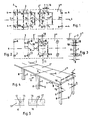
- the table system 1 shown in Fig. 1 consists of three identical rectangular table elements 2, which are to be joined together in a form-fitting manner at their abutting edge regions 3.
- the edge areas 3 have connecting blocks 4 which simultaneously form the table feet 5 (see FIG. 4).
- the connecting blocks 4 are arranged asymmetrically with respect to the center line of symmetry 6.
- the connecting blocks 4 have the following arrangement to each other: the connecting block 7 is on one side at a distance a, the connecting block 8 on other side at a distance c from the symmetry center line 6.
- the connecting blocks 7, 8 each engage in a form-fitting manner.
- Each edge area accordingly has a connecting block 7 designed as a table base at a distance a and a corresponding connecting block 8 at a distance c from the symmetry center line 6, the table feet or connecting blocks being arranged diagonally in mirror image on the table element. These diagonals are drawn in in FIG. 1 with reference number 9 for the table feet 7 and reference number 10 for the table feet 8.
- the individual table elements 2, 2 ', 2 ⁇ are joined together at their abutting edge regions 3, so that in each case a connecting block 7 of the one table element at a distance a from the symmetry center line 6 with the width b interacts positively with a connecting block 8 of the other Table element at a distance c from the center of symmetry.
- the table elements can therefore be rotated through 180 °, since the respective connecting blocks 4, 7, 8 are arranged diagonally symmetrically on each table element (Diagonal 9, 10).
- the connecting blocks 4, 7, 8 are simultaneously formed as table feet 5 as shown in Fig. 4.
- each table leg 5 or connecting block 4 relates to a distance perpendicular to the center line of symmetry 6.
- the side edge width s of each table leg is irrelevant for the dimensioning rule between a, b and c.
- the side edge width of the table base 7 with s7 and that of the table base 8 is designated with s8.
- FIG. 2 The representation of FIG. 2 in a perspective view is shown in FIG. 4.
- the same parts are identified by the same reference numerals.
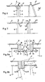
- FIG. 5 An alternative embodiment of the invention results from the illustration in FIG. 5.
- the connecting blocks 4 or table feet 5 are not arranged asymmetrically at a distance a, c from the respective symmetry center line 6, but symmetrically thereto.
- the positive connection is achieved by a wavy or sinusoidal connecting surface 12 between the adjacent table feet 13, 14 or by a trapezoidal connecting surface 15 between the two table feet 16, 17.
- the connecting blocks 4, 7, 8 or table feet 5 protrude beyond the edge area 3 of the respective table element 2 by the amount t, this protruding area 18 with the width t in each case in the pushed-together state of the table elements the adjacent table element protrudes so that the Intended positive connection or overlap of the table feet, 7, 8 results.
- the arrangement of the table elements 2, 2 ', 2 ⁇ shown in side view in FIG. 6, 8a, 8b shows the wedge-shaped design of the upper regions 19 of the table feet 5, 7, 8.
- the front protruding area 18 of the table feet 7, 8 is designed as a wedge-shaped area 19. With the horizontal becomes. an angle ⁇ 10 ° is formed.
- the area 21 lying to the side of the edge area 3 below the table top 20 is also designed as a wedge-shaped undercut 21 with an angle ⁇ ⁇ 10 ° in order to act as a counterpart to the protruding area 18 or wedge-shaped upper area 19.
- the upward wedge-shaped area 22 of the table base 7 therefore grips, as shown in FIG. 8b, below the wedge-shaped area 23 of the table base 8.
- the wedge-shaped area 24 of the table base 8 comes into engagement with the wedge-shaped undercut 25 of the table base 7 or the Tabletop underside.
- the table element as shown in FIGS. 6 and 8b, has to be raised laterally in order to be able to perform a pivoting movement (arrow 26).
- the wedge-shaped surfaces 22 to 25 have the effect that it is not possible to pull apart the assembled table elements without lifting a table element 2 due to the protruding area 18 engaging behind the undercut 23, 25.
- a bare insert or table top 27 is shown without the otherwise usual four feet.
- the connection is made by means of connecting blocks 4, which act like sawn-off table feet.
- they protrude beyond the overhang area 18 beyond the edge area 3 and are arranged identically, as described in FIG. 1 for the connecting blocks 4 and 7, 8, respectively.
- Corresponding reference numerals are therefore shown in FIG. 7.
- a falling down of the inserted table top 27 cannot occur since it always rests on the protruding area of the two adjacent table elements 2, 2 ⁇ .
- an auxiliary foot 28 can be provided, which is set up until the further.
- connection blocks 4, 7, 8 in FIG. 7 are connected in the same way with wedge-shaped connections d. H. with a wedge lock as described in Fig. 8a and b analog.
- the table system according to the invention can be adapted to different geometrical shapes.
- rectangular table elements 2 as shown in FIGS. 1 and 2 can be combined with table elements 29 in the form of segments of a circle.
- the only decisive factor is that the respective edge regions 3 are constructed in accordance with the description of the invention relating to FIGS. 1 to 4. Accordingly, table feet 7, 8 act together at a distance a or c from the symmetry center line 6.
- the table elements are designed as trapezoidal table elements 30 in order to obtain a polygonal arrangement of the table elements.
- the table feet 5 are arranged according to the diagram in FIGS. 1 to 4, the table feet 7, 8 designed as connecting blocks 4 again being arranged asymmetrically at a distance a, c from the center line of symmetry 6.
- the connecting blocks or table feet 4, 5 are always perpendicular to the edge regions 3.
- a corresponding trapezoidal table element is shown in isolation in FIG. 10a.
- a combination of such a table element 30 with a rectangular table element 2 is shown in FIG. 10b.
- 10c shows a composition of exclusively trapezoidal table elements 30.
- FIG. 11a shows a rectangular, in particular a square table element 31 with only one connecting block 4 on each side edge or edge area 3.
- the connecting blocks 4, which in turn serve as table feet 5, are arranged in such a way that their side flank 32 touch the respective center line of symmetry 6, 6 ', again opposing connecting blocks are arranged diagonally in mirror image.
- the right in Fig. 11a connecting block 4 is below the symmetry center line 6 and the left, opposite connecting block 4 'above this symmetry center line 6.
- the mirror-image diagonal arrangement of the connecting blocks 4 accordingly results in an arrangement possibility according to FIG. 11b, the connecting blocks each of those which abut one another Edge areas come to rest positively next to each other.
- the width b of the connecting blocks 4 is irrelevant, since the contact surfaces always lie only on the symmetry center lines 6.
- FIG. 3 A circular table element 33 is shown in FIG. This table element is a supplement to the table elements according to FIGS. 9 and 10 or as a semicircular termination of the arrangement according to FIG. 2 or 4.
- the connecting blocks 7, 8 or corresponding table feet 5 are again in accordance with the same scheme as in FIGS 4, arranged.
- FIG. 13 shows in FIG. 13 a a desk 34, which on its rear long side 35 has two table feet 5, but on the transverse side 36 each has only one table base 5 '.
- the end face 37 for arranging a desk chair has no table feet 5.
- the table in FIG. 13a is shown in front view in FIG. 13b as well as in the two side views.
- three desks according to FIG. 13a are arranged side by side, the side feet 5 'in turn exerting a positive connection according to the invention.
- the inner table base 7 at a distance
- the outer table base 8 at a distance c from the symmetry center line 6 ', which is formed by the rear longitudinal side 35.
- the width of the respective table base is again b.
- the lateral arrangement of the table feet 5 'and 7, 8 in Fig. 13a to 13d results from the fact that when
- Embodiment of the invention according to FIGS. 1 and 2 used only table halves, which result from the cut in the symmetry center line.
- FIG. 13d In the exemplary embodiment of the invention according to FIG. 13d, four desks are accordingly assembled as shown in FIG. 13a.
- the arrangement of the connecting blocks 4 or corresponding table feet 5 is also asymmetrical in the smaller distance a for the inner table foot 7 and in the larger distance c for the respective outer table foot 8 with a width b of the inner table foot 7. This corresponds to the connection system according to FIG. 1 to 4.
- the lateral individual table base 5 ' is arranged at a distance a from the rear table edge 35 or symmetry center line 6' to cooperate with the corresponding table base 8 at a distance c from the longitudinal edge of the adjacent desk.
- the rear longitudinal side 35 of the desk 34 therefore serves simultaneously as a symmetry center line 6 'with respect to the arrangement of the table feet 5' on the transverse sides 36.
- the arrangement according to FIG. 13d shows that both the table leg arrangement on the long side 35 and on the transverse side 36 in their Distances are coordinated so that there is a positive wedging of the desks according to the principle of the invention.
- the invention is not restricted to the exemplary embodiment shown and described. Rather, it also encompasses all professional training courses without their own inventive content.
Landscapes
- Machine Tool Units (AREA)
- Furniture Connections (AREA)
- Signal Processing For Digital Recording And Reproducing (AREA)
- Electrical Discharge Machining, Electrochemical Machining, And Combined Machining (AREA)
- Two-Way Televisions, Distribution Of Moving Picture Or The Like (AREA)
- Tables And Desks Characterized By Structural Shape (AREA)
Priority Applications (1)
| Application Number | Priority Date | Filing Date | Title |
|---|---|---|---|
| AT90101182T ATE81951T1 (de) | 1989-02-01 | 1990-01-22 | Tischsystem. |
Applications Claiming Priority (2)
| Application Number | Priority Date | Filing Date | Title |
|---|---|---|---|
| DE3902926 | 1989-02-01 | ||
| DE3902926A DE3902926A1 (de) | 1989-02-01 | 1989-02-01 | Tischsystem |
Publications (3)
| Publication Number | Publication Date |
|---|---|
| EP0380995A2 true EP0380995A2 (fr) | 1990-08-08 |
| EP0380995A3 EP0380995A3 (fr) | 1991-01-02 |
| EP0380995B1 EP0380995B1 (fr) | 1992-11-04 |
Family
ID=6373202
Family Applications (1)
| Application Number | Title | Priority Date | Filing Date |
|---|---|---|---|
| EP90101182A Expired - Lifetime EP0380995B1 (fr) | 1989-02-01 | 1990-01-22 | Système à tables |
Country Status (3)
| Country | Link |
|---|---|
| EP (1) | EP0380995B1 (fr) |
| AT (1) | ATE81951T1 (fr) |
| DE (2) | DE3902926A1 (fr) |
Cited By (2)
| Publication number | Priority date | Publication date | Assignee | Title |
|---|---|---|---|---|
| DE4026910A1 (de) * | 1990-08-25 | 1992-02-27 | Esslinger Hartmut H | Bausatz fuer buerotische mit tischplatte und tischgestell |
| DE10052054A1 (de) * | 2000-10-19 | 2002-04-25 | Drabert Gmbh | Tisch mit einer Verkettungsvorrichtung |
Families Citing this family (1)
| Publication number | Priority date | Publication date | Assignee | Title |
|---|---|---|---|---|
| US5595126A (en) * | 1995-08-10 | 1997-01-21 | Yeh; Hsin-Ho | Shape-changeable table |
Family Cites Families (4)
| Publication number | Priority date | Publication date | Assignee | Title |
|---|---|---|---|---|
| US2031398A (en) * | 1935-07-06 | 1936-02-18 | Arthur F Wagoner | Table top extension clamp |
| US2857223A (en) * | 1958-05-23 | 1958-10-21 | Lawrence M Furey | Connected tables |
| FR1575193A (fr) * | 1968-07-26 | 1969-07-18 | ||
| GB1576215A (en) * | 1978-03-22 | 1980-10-01 | Tapper R E | Items of furniture |
-
1989
- 1989-02-01 DE DE3902926A patent/DE3902926A1/de not_active Withdrawn
-
1990
- 1990-01-22 DE DE9090101182T patent/DE59000416D1/de not_active Expired - Lifetime
- 1990-01-22 AT AT90101182T patent/ATE81951T1/de not_active IP Right Cessation
- 1990-01-22 EP EP90101182A patent/EP0380995B1/fr not_active Expired - Lifetime
Cited By (2)
| Publication number | Priority date | Publication date | Assignee | Title |
|---|---|---|---|---|
| DE4026910A1 (de) * | 1990-08-25 | 1992-02-27 | Esslinger Hartmut H | Bausatz fuer buerotische mit tischplatte und tischgestell |
| DE10052054A1 (de) * | 2000-10-19 | 2002-04-25 | Drabert Gmbh | Tisch mit einer Verkettungsvorrichtung |
Also Published As
| Publication number | Publication date |
|---|---|
| EP0380995A3 (fr) | 1991-01-02 |
| ATE81951T1 (de) | 1992-11-15 |
| DE59000416D1 (de) | 1992-12-10 |
| DE3902926A1 (de) | 1990-04-19 |
| EP0380995B1 (fr) | 1992-11-04 |
Similar Documents
| Publication | Publication Date | Title |
|---|---|---|
| EP0264589A2 (fr) | Système de table | |
| EP0310546A1 (fr) | Disposition variable de cadres de montage | |
| DE1609883B2 (de) | Plattenelement zur Bildung von lichtdurchlässigen Decken oder Wänden | |
| DE202013011496U1 (de) | Aus Platten bestehendes universelles Möbelstück | |
| DE1965012A1 (de) | Bauelemente,insbesondere Spielzeug- und Hochbau-Bauelemente | |
| DE4124109A1 (de) | Bauelement fuer gefaelledach-systeme | |
| EP0380995B1 (fr) | Système à tables | |
| DE2636858A1 (de) | Plattenfoermiges wandelement aus stranggepresstem kunststoff | |
| DE3035238A1 (de) | Tisch | |
| DE9108211U1 (de) | Modulare Kunststoffklappe | |
| DE2252165C3 (de) | Schichtkern für Transformatoren oder Drosselspulen großer Leistung | |
| DE2814192A1 (de) | Steckbausystem fuer spielzwecke | |
| DE8202245U1 (de) | Rahmenkonstruktion, insbesondere fuer moebel | |
| DE2932520C2 (de) | Bauelement aus einem dreieckförmigen Rahmen | |
| DE8907749U1 (de) | Bausatz aus Beton-Pflastersteinen | |
| DE7101715U (de) | Tisch mn polygonaler Tischplatte | |
| DE2906829A1 (de) | Bausatz zur montage von moebeln | |
| DE19745073A1 (de) | Verbindungselement für Möbelsysteme | |
| DE19533222C1 (de) | Polstermöbelgestell | |
| DE2630289A1 (de) | Formstein fuer verbundpflasterung | |
| DE3444957C1 (de) | Möbel, das als Tisch, Hocker, Blumenständer o.ä. einsetzbar ist | |
| DE7713539U1 (de) | Stahlregal mit Hakenlaschenverbindungen | |
| EP1057935A1 (fr) | Pierre à paver | |
| AT271548B (de) | Verbundpflasterstein, insbesondere Betonformstein | |
| EP2110494B1 (fr) | Système de coffrage |
Legal Events
| Date | Code | Title | Description |
|---|---|---|---|
| PUAI | Public reference made under article 153(3) epc to a published international application that has entered the european phase |
Free format text: ORIGINAL CODE: 0009012 |
|
| AK | Designated contracting states |
Kind code of ref document: A2 Designated state(s): AT CH DE FR GB IT LI SE |
|
| PUAL | Search report despatched |
Free format text: ORIGINAL CODE: 0009013 |
|
| AK | Designated contracting states |
Kind code of ref document: A3 Designated state(s): AT CH DE FR GB IT LI SE |
|
| RHK1 | Main classification (correction) |
Ipc: A47B 87/00 |
|
| 17P | Request for examination filed |
Effective date: 19901221 |
|
| 17Q | First examination report despatched |
Effective date: 19920409 |
|
| GRAA | (expected) grant |
Free format text: ORIGINAL CODE: 0009210 |
|
| AK | Designated contracting states |
Kind code of ref document: B1 Designated state(s): AT CH DE FR GB IT LI SE |
|
| REF | Corresponds to: |
Ref document number: 81951 Country of ref document: AT Date of ref document: 19921115 Kind code of ref document: T |
|
| ET | Fr: translation filed | ||
| GBT | Gb: translation of ep patent filed (gb section 77(6)(a)/1977) | ||
| REF | Corresponds to: |
Ref document number: 59000416 Country of ref document: DE Date of ref document: 19921210 |
|
| ITF | It: translation for a ep patent filed | ||
| PLBE | No opposition filed within time limit |
Free format text: ORIGINAL CODE: 0009261 |
|
| STAA | Information on the status of an ep patent application or granted ep patent |
Free format text: STATUS: NO OPPOSITION FILED WITHIN TIME LIMIT |
|
| 26N | No opposition filed | ||
| EAL | Se: european patent in force in sweden |
Ref document number: 90101182.5 |
|
| PGFP | Annual fee paid to national office [announced via postgrant information from national office to epo] |
Ref country code: AT Payment date: 20000114 Year of fee payment: 11 |
|
| PGFP | Annual fee paid to national office [announced via postgrant information from national office to epo] |
Ref country code: GB Payment date: 20000117 Year of fee payment: 11 |
|
| PGFP | Annual fee paid to national office [announced via postgrant information from national office to epo] |
Ref country code: FR Payment date: 20000125 Year of fee payment: 11 |
|
| PGFP | Annual fee paid to national office [announced via postgrant information from national office to epo] |
Ref country code: SE Payment date: 20000128 Year of fee payment: 11 |
|
| PGFP | Annual fee paid to national office [announced via postgrant information from national office to epo] |
Ref country code: CH Payment date: 20000330 Year of fee payment: 11 |
|
| PG25 | Lapsed in a contracting state [announced via postgrant information from national office to epo] |
Ref country code: GB Free format text: LAPSE BECAUSE OF NON-PAYMENT OF DUE FEES Effective date: 20010122 Ref country code: AT Free format text: LAPSE BECAUSE OF NON-PAYMENT OF DUE FEES Effective date: 20010122 |
|
| PG25 | Lapsed in a contracting state [announced via postgrant information from national office to epo] |
Ref country code: SE Free format text: LAPSE BECAUSE OF NON-PAYMENT OF DUE FEES Effective date: 20010123 |
|
| PG25 | Lapsed in a contracting state [announced via postgrant information from national office to epo] |
Ref country code: LI Free format text: LAPSE BECAUSE OF NON-PAYMENT OF DUE FEES Effective date: 20010131 Ref country code: CH Free format text: LAPSE BECAUSE OF NON-PAYMENT OF DUE FEES Effective date: 20010131 |
|
| EUG | Se: european patent has lapsed |
Ref document number: 90101182.5 |
|
| GBPC | Gb: european patent ceased through non-payment of renewal fee |
Effective date: 20010122 |
|
| REG | Reference to a national code |
Ref country code: CH Ref legal event code: PL |
|
| PG25 | Lapsed in a contracting state [announced via postgrant information from national office to epo] |
Ref country code: FR Free format text: LAPSE BECAUSE OF NON-PAYMENT OF DUE FEES Effective date: 20010928 |
|
| REG | Reference to a national code |
Ref country code: FR Ref legal event code: ST |
|
| PGFP | Annual fee paid to national office [announced via postgrant information from national office to epo] |
Ref country code: DE Payment date: 20020206 Year of fee payment: 13 |
|
| PG25 | Lapsed in a contracting state [announced via postgrant information from national office to epo] |
Ref country code: DE Free format text: LAPSE BECAUSE OF NON-PAYMENT OF DUE FEES Effective date: 20030801 |
|
| PG25 | Lapsed in a contracting state [announced via postgrant information from national office to epo] |
Ref country code: IT Free format text: LAPSE BECAUSE OF NON-PAYMENT OF DUE FEES;WARNING: LAPSES OF ITALIAN PATENTS WITH EFFECTIVE DATE BEFORE 2007 MAY HAVE OCCURRED AT ANY TIME BEFORE 2007. THE CORRECT EFFECTIVE DATE MAY BE DIFFERENT FROM THE ONE RECORDED. Effective date: 20050122 |