EP0381004B1 - Tube à décharge - Google Patents
Tube à décharge Download PDFInfo
- Publication number
- EP0381004B1 EP0381004B1 EP90101235A EP90101235A EP0381004B1 EP 0381004 B1 EP0381004 B1 EP 0381004B1 EP 90101235 A EP90101235 A EP 90101235A EP 90101235 A EP90101235 A EP 90101235A EP 0381004 B1 EP0381004 B1 EP 0381004B1
- Authority
- EP
- European Patent Office
- Prior art keywords
- electrode
- discharge tube
- cathode
- tubular casing
- discharge
- Prior art date
- Legal status (The legal status is an assumption and is not a legal conclusion. Google has not performed a legal analysis and makes no representation as to the accuracy of the status listed.)
- Expired - Lifetime
Links
- 239000010410 layer Substances 0.000 claims description 25
- 239000002344 surface layer Substances 0.000 claims description 13
- 229910052751 metal Inorganic materials 0.000 claims description 11
- 239000002184 metal Substances 0.000 claims description 11
- RYGMFSIKBFXOCR-UHFFFAOYSA-N Copper Chemical compound [Cu] RYGMFSIKBFXOCR-UHFFFAOYSA-N 0.000 claims description 6
- PXHVJJICTQNCMI-UHFFFAOYSA-N Nickel Chemical compound [Ni] PXHVJJICTQNCMI-UHFFFAOYSA-N 0.000 claims description 6
- 229910052802 copper Inorganic materials 0.000 claims description 6
- 239000010949 copper Substances 0.000 claims description 6
- 239000011261 inert gas Substances 0.000 claims description 5
- 229910052759 nickel Inorganic materials 0.000 claims description 3
- 239000007789 gas Substances 0.000 description 7
- 238000009713 electroplating Methods 0.000 description 3
- 239000011521 glass Substances 0.000 description 3
- 238000011056 performance test Methods 0.000 description 3
- 229910001220 stainless steel Inorganic materials 0.000 description 3
- 239000010935 stainless steel Substances 0.000 description 3
- IJGRMHOSHXDMSA-UHFFFAOYSA-N Atomic nitrogen Chemical compound N#N IJGRMHOSHXDMSA-UHFFFAOYSA-N 0.000 description 2
- 230000001154 acute effect Effects 0.000 description 2
- PNEYBMLMFCGWSK-UHFFFAOYSA-N aluminium oxide Inorganic materials [O-2].[O-2].[O-2].[Al+3].[Al+3] PNEYBMLMFCGWSK-UHFFFAOYSA-N 0.000 description 2
- 239000000919 ceramic Substances 0.000 description 2
- 229910000679 solder Inorganic materials 0.000 description 2
- UFHFLCQGNIYNRP-UHFFFAOYSA-N Hydrogen Chemical compound [H][H] UFHFLCQGNIYNRP-UHFFFAOYSA-N 0.000 description 1
- 238000010586 diagram Methods 0.000 description 1
- 230000000694 effects Effects 0.000 description 1
- PCHJSUWPFVWCPO-UHFFFAOYSA-N gold Chemical compound [Au] PCHJSUWPFVWCPO-UHFFFAOYSA-N 0.000 description 1
- 229910052737 gold Inorganic materials 0.000 description 1
- 239000010931 gold Substances 0.000 description 1
- 239000001257 hydrogen Substances 0.000 description 1
- 229910052739 hydrogen Inorganic materials 0.000 description 1
- 238000011835 investigation Methods 0.000 description 1
- XEEYBQQBJWHFJM-UHFFFAOYSA-N iron Substances [Fe] XEEYBQQBJWHFJM-UHFFFAOYSA-N 0.000 description 1
- 229910052742 iron Inorganic materials 0.000 description 1
- 238000012423 maintenance Methods 0.000 description 1
- 238000004519 manufacturing process Methods 0.000 description 1
- 239000000463 material Substances 0.000 description 1
- 239000000203 mixture Substances 0.000 description 1
- 229910052757 nitrogen Inorganic materials 0.000 description 1
- 230000002093 peripheral effect Effects 0.000 description 1
- 238000007747 plating Methods 0.000 description 1
- 238000007493 shaping process Methods 0.000 description 1
- ZVWKZXLXHLZXLS-UHFFFAOYSA-N zirconium nitride Chemical compound [Zr]#N ZVWKZXLXHLZXLS-UHFFFAOYSA-N 0.000 description 1
Images
Classifications
-
- H—ELECTRICITY
- H01—ELECTRIC ELEMENTS
- H01J—ELECTRIC DISCHARGE TUBES OR DISCHARGE LAMPS
- H01J17/00—Gas-filled discharge tubes with solid cathode
- H01J17/02—Details
- H01J17/04—Electrodes; Screens
-
- H—ELECTRICITY
- H01—ELECTRIC ELEMENTS
- H01T—SPARK GAPS; OVERVOLTAGE ARRESTERS USING SPARK GAPS; SPARKING PLUGS; CORONA DEVICES; GENERATING IONS TO BE INTRODUCED INTO NON-ENCLOSED GASES
- H01T1/00—Details of spark gaps
Definitions
- This invention relates to a discharge tube as indicated in the precharacterizing part of claim 1.
- An ignition system of an automobile engine or the like is adapted to supply a high voltage to an ignition plug to produce a spark.
- an ignition system with a so-called series gap is employed wherein a discharge gap is provided in series to an ignition plug.
- a discharge tube is employed wherein inert gas is enclosed in a tube and a pair of electrodes are provided at the opposite ends of the tube.
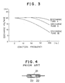
- FIG. 4 An exemplary one of such discharge tubes is shown in FIG. 4. Referring to FIG. 4, the discharge tube shown includes a glass tube 21 and a pair of metal wire electrodes 22 each covered with a zirconium nitride layer not shown and mounted in an enclosed relationship at the opposite end portions of the glass tube 21. Pressurized mixture gas of nitrogen and hydrogen is filled in the glass tube 21.
- the discharge starting voltage of such a discharge tube must necessarily be high to some degree. Accordingly, the discharge tube has a problem that, if the distance between the electrodes is increased to this end, then the discharge maintaining voltage of the discharge tube is also increased and consequently the loss of energy to be supplied to an ignition plug is increased. Also there is another problem that the exhaustion of the electrodes is increased and the life of the discharge tube is reduced accordingly.
- the inventors have made an investigation for improvement of making opposing faces of a pair of electrodes less acute or non-acute to raise the discharge voltage and lower the discharge maintaining voltage. Then, it has been found out that improvement in accuracy of the discharge voltage can be attained by the provision of a large number of convex and/or concave portions on a surface at least of the cathode. However, no solution has been found out yet to the problem that the discharge voltage drops as the frequency of discharge rises as described above.
- the electrode member of the cathode electrode being composed of a layered metal body including a ground layer and a thin surface layer formed on a surface of the ground layer opposing to the anode electrode and having a considerably smaller thickness than the ground layer.
- the electrode member may be of the two-layer structure only including the ground layer and the thin surface layer or of a three- or more-layer structure including an additional layer or layers.
- the thin surface layer can be formed on the ground layer by plating or the like, and desirably the thickness of the surface layer is within the range from 5 to 20 »m.
- the electrode member of the cathode electrode has another similar thin surface layer formed on the other surface of the ground layer thereof.
- the electrode member of the anode electrode may be composed of a layered metal body including a ground layer and a thin surface layer formed on one or each of the opposite surfaces of the ground layer.
- the shape of the cathode electrode and/or the anode electrode can be determined suitably such that it may have an optimum characteristic in accordance with an application of the discharge tube.
- the discharge tube of the present invention even if the frequency of discharge rises, the discharge voltage does not drop very much. Since the change of the discharge voltage with respect to the frequency of ignition is improved in this manner, the discharge tube is advantageous in that it exhibits an excellent effect in maintenance of a stabilized running condition even if a considerable change takes place in the number of revolution of an engine of an automobile or the like in which the discharge tube is incorporated.
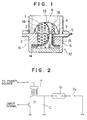
- the discharge tube shown includes a hollow tubular casing 8 formed from an alumina ceramics, and a cathode electrode 11 and an anode electrode 12 secured to the axial opposite ends of the tubular casing 8 and sealed with a suitable means such as silver solder not shown so as to define a hollow spacing 13 in the casing 8.
- the cathode electrode 11 includes an electrode base 2 substantially in the form of a disk secured to the tubular casing 8, and an electrode member 1 having a generally semi-spherical shape and fitted on and secured to a hub portion 14 of the electrode base 2 by means of a metal ring 3.
- the electrode member 1 has a large number of perforations 16 of a suitable size formed at a suitable pitch thereon.
- the anode electrode 12 includes an electrode base 6 substantially in the form of a disk secured to the tubular casing 8, and an electrode member 4 having a substantially flat surface and fitted on and secured to a hub portion 15 of the electrode base 6 by means of a metal ring 7.
- the electrode member 4 also has a large number of perforations 16 of a similar size formed at a similar suitable pitch thereon.
- a gas conduit 5 extends axially through the center of the electrode base 6. Upon production of the discharge tube, suitable inert gas is introduced into the inner hollow spacing of the discharge tube by way of the gas conduit 5 so as to replace with the air. After such replacement, an outer end of the gas conduit 5 is compressed to seal the conduit 5.
- Each of the electrode members 1 and 4 is formed from a layered body in the form of a plate which at least includes, though not shown, a ground layer which is a copper plate having a thickness of about 0. 5 mm, and a thin surface layer formed on each of the opposite surfaces of the ground layer and having a significantly small thickness of 5 to 20 »m, preferably of 10 »m, comparing with the ground layer.
- the surface layer is formed by electroplating of nickel.
- a copper plate of a thickness of 0. 5 mm having a large number of perforations of about 0. 5 mm formed at a pitch of about 1 mm therein was prepared.
- the perforated copper plate was shaped by press work so as to be rounded at peripheral edge portions thereof, and electroplating of nickel was performed to a thickness of about 10 »m on the opposite inner and outer surfaces of the perforated copper plate.
- An electrode member 1 obtained in this manner was fitted on and secured to an electrode base 2 by means of a metal ring 3 to form a cathode electrode 11 as shown in FIG. 1.
- Another electrode 4 having a substantially flat surface was produced in a similar manner and fitted on and secured to an electrode base 6, which had a gas conduit 5 extending therethrough, by means of another metal ring 7 to form an anode electrode 12.
- the cathode electrode 11 and the anode electrode 12 produced in this manner were assembled in an opposing relationship to each other to the opposite ends of a tubular casing 8 of an alumina ceramics and then sealed with silver solder. Then, inert gas was introduced for replacement with air into the internal hollow spacing 13 of the discharge tube by way of the gas conduit 5, and then an outer end of the conduit 5 was compressed for enclosure, thereby obtaining a discharge tube I according to the present invention.
- the electrodes 1 and 4 instead of forming the electrodes 1 and 4 from perforated copper plates, they were formed by shaping similar perforated stainless steel plates by press work and then performing electroplating of gold to a thickness of about 10 »m on the opposite inner and outer surfaces of the perforated stainless steel plates. Then, a discharge tube II of the present invention was produced by assembling the electrode plates 1 and 4 to a tubular casing 8 in a similar manner as the example 1 described hereinabove.
- the ignition system shown includes an ignition coil T, a pair of discharge gaps G1 and G2 provided by a discharge tube and an ignition plug, respectively, and a floating capacitance C provided by a high tension cable, a distributor cap and so forth.
- An ignition signal is transmitted to the ignition coil T by way of a transistor Tr.
Landscapes
- Ignition Installations For Internal Combustion Engines (AREA)
Claims (4)
- Un tube à décharge, comprenant une enveloppe tubulaire creuse (8), et une paire d'électrodes cathode et anode (11, 12) se faisant face, fixées aux extrémités axiales opposées de ladite enveloppe tubulaire (8) pour définir dans ladite enveloppe tubulaire un espace creux fermé (13) dans lequel est introduit un gaz inerte de telle sorte qu'une décharge peut ètre amorcée par l'application d'une tension d'impulsion entre lesdites électrodes cathode. et anode (11, 12), chacune desdites electrodes comprenant une base d'électrode (2, 6) fixée à ladite enveloppe tubulaire (8) et un élément d'électrode (1, 4) monté de façon fixe sur ladite baie d'électrode (2, 6) dans ledit espace creux (13), la base d'électrode (2) de ladite électrode cathode (11) ayant sensiblement la forme d'un disque fixé à l'enveloppe tubulaire (8), ledit élément d'électrode (1) de ladite électrode cathode (11) ayant une forme généralement semi-sphérique et lesdits éléments d'électrode (1, 4) étant enrobés d'une couche :
caractérisé en ce que
ledit élément d'électrode (1) de ladite électrode cathode (11) est monté et fixé sur une partie moyeu (14) de la base d'électrode (2) au moyen d'un anneau métallique (3), comporte un grand nombre de perforations (16), et est composé d'un corps métallique à couches comprenant une couche de base en cuivre et une mince souche de surface en nickel formée sur une surface de ladite couche de base faisant face à ladite électrode anode (12). - Un tube à décharge selon la revendication 1, dans lequel ladite mince couche de surface de ladite électrode cathode (11) a une épaisseur comprise entre 5 et 20 »m.
- Un tube à décharge selon la revendication 1, dans lequel ledit élément d'électrodes (1) de ladite électrode cathode (11) comporte une autre mince couche de surface similaire, formée sur l'autre surface de ladite couche de base de celui-ci.
- Un tube à décharge selon la revendication 1, dans lequel ledit élément d'électrode (4) de ladite électrode anode (3) est composé d'un corps métallique à couches comprenant une couche de base et une mince couche de surface formée sur l'une ou chacune des surfaces opposées de ladite couche de base.
Applications Claiming Priority (2)
| Application Number | Priority Date | Filing Date | Title |
|---|---|---|---|
| JP1017773A JPH02230679A (ja) | 1989-01-30 | 1989-01-30 | 放電管 |
| JP17773/89 | 1989-01-30 |
Publications (2)
| Publication Number | Publication Date |
|---|---|
| EP0381004A1 EP0381004A1 (fr) | 1990-08-08 |
| EP0381004B1 true EP0381004B1 (fr) | 1994-07-20 |
Family
ID=11953035
Family Applications (1)
| Application Number | Title | Priority Date | Filing Date |
|---|---|---|---|
| EP90101235A Expired - Lifetime EP0381004B1 (fr) | 1989-01-30 | 1990-01-22 | Tube à décharge |
Country Status (4)
| Country | Link |
|---|---|
| EP (1) | EP0381004B1 (fr) |
| JP (1) | JPH02230679A (fr) |
| CA (1) | CA2007758A1 (fr) |
| DE (1) | DE69010706T2 (fr) |
Families Citing this family (1)
| Publication number | Priority date | Publication date | Assignee | Title |
|---|---|---|---|---|
| DE19741658A1 (de) * | 1997-09-16 | 1999-03-18 | Siemens Ag | Gasgefüllte Entladungsstrecke |
Family Cites Families (2)
| Publication number | Priority date | Publication date | Assignee | Title |
|---|---|---|---|---|
| US3612937A (en) * | 1969-10-08 | 1971-10-12 | Sergei Alexandrovich Smirnov | Low-pressure controlled discharge device with trigger electrode within hollow cathode |
| JPS493264A (fr) * | 1972-04-22 | 1974-01-12 |
-
1989
- 1989-01-30 JP JP1017773A patent/JPH02230679A/ja active Pending
-
1990
- 1990-01-15 CA CA002007758A patent/CA2007758A1/fr not_active Abandoned
- 1990-01-22 DE DE69010706T patent/DE69010706T2/de not_active Expired - Fee Related
- 1990-01-22 EP EP90101235A patent/EP0381004B1/fr not_active Expired - Lifetime
Non-Patent Citations (2)
| Title |
|---|
| "GAS DISCHARGE TUBES", H.L. van der Horst, 1964, Philips Technical Library, pages 150-157. * |
| SOVIET INVENTIONS ILLUSTRATED, section El, week D 29, August 26, 1981 DERWENT PUBLICATIONS LTD., London, X 12 * |
Also Published As
| Publication number | Publication date |
|---|---|
| DE69010706D1 (de) | 1994-08-25 |
| EP0381004A1 (fr) | 1990-08-08 |
| DE69010706T2 (de) | 1994-10-27 |
| JPH02230679A (ja) | 1990-09-13 |
| CA2007758A1 (fr) | 1990-07-30 |
Similar Documents
| Publication | Publication Date | Title |
|---|---|---|
| EP0990127B1 (fr) | Transducteur de pression capacitif a support d'electrode ameliore | |
| US3958144A (en) | Spark plug | |
| US4771209A (en) | Spark igniter having precious metal ground electrode inserts | |
| US4406968A (en) | Sparkplug for internal combustion engine | |
| EP1053459A1 (fr) | Conception de capteur de pression capacitif | |
| KR960703282A (ko) | 서피스 디스차지 섹션을 가진 스파크 플러그 (Sparking plug with surface discharge section) | |
| JPH06201503A (ja) | 容量型圧力変換器 | |
| US5510667A (en) | Spark plug with an electrode having a platinum-nickel fiber composite material | |
| EP0381004B1 (fr) | Tube à décharge | |
| CA1161319A (fr) | Rotor de distributeur d'allumage eliminant les interferences radiofrequences | |
| US5331249A (en) | Discharge tube | |
| US4593341A (en) | Tubular capacitor end terminations | |
| WO2018070129A1 (fr) | Bougie d'allumage et son procédé de fabrication | |
| US3646281A (en) | Electrostatic transducer with vented diaphragm | |
| CN1042858C (zh) | 微小极间距电容式力敏传感器及其制造方法 | |
| JP2002270329A (ja) | ガス封入スイッチング放電管 | |
| JPH05198348A (ja) | 内燃機関用スパークプラグ | |
| US4091436A (en) | Knob type surge voltage arrester | |
| EP0466106B1 (fr) | Tube à décharge | |
| US4937494A (en) | High pressure discharge lamp having an electrode lead-through with a positioning crimp | |
| EP0800247B1 (fr) | Système d'allumage du type à double polarité pour groupe de bougies d'allumage | |
| EP1544970A1 (fr) | Bougie d'allumage | |
| US4591952A (en) | Electrical element such as a tantalum and solid-electrolyte capacitor | |
| CN221006213U (zh) | 一种应变片及应用该应变片的筒柱式传感器 | |
| US3193911A (en) | Method for making a pressureresponsive device |
Legal Events
| Date | Code | Title | Description |
|---|---|---|---|
| PUAI | Public reference made under article 153(3) epc to a published international application that has entered the european phase |
Free format text: ORIGINAL CODE: 0009012 |
|
| AK | Designated contracting states |
Kind code of ref document: A1 Designated state(s): DE FR GB |
|
| 17P | Request for examination filed |
Effective date: 19901113 |
|
| 17Q | First examination report despatched |
Effective date: 19921202 |
|
| GRAA | (expected) grant |
Free format text: ORIGINAL CODE: 0009210 |
|
| AK | Designated contracting states |
Kind code of ref document: B1 Designated state(s): DE FR GB |
|
| REF | Corresponds to: |
Ref document number: 69010706 Country of ref document: DE Date of ref document: 19940825 |
|
| ET | Fr: translation filed | ||
| PLBE | No opposition filed within time limit |
Free format text: ORIGINAL CODE: 0009261 |
|
| STAA | Information on the status of an ep patent application or granted ep patent |
Free format text: STATUS: NO OPPOSITION FILED WITHIN TIME LIMIT |
|
| 26N | No opposition filed | ||
| REG | Reference to a national code |
Ref country code: GB Ref legal event code: IF02 |
|
| PGFP | Annual fee paid to national office [announced via postgrant information from national office to epo] |
Ref country code: FR Payment date: 20050110 Year of fee payment: 16 |
|
| PGFP | Annual fee paid to national office [announced via postgrant information from national office to epo] |
Ref country code: GB Payment date: 20050119 Year of fee payment: 16 |
|
| PGFP | Annual fee paid to national office [announced via postgrant information from national office to epo] |
Ref country code: DE Payment date: 20050120 Year of fee payment: 16 |
|
| PG25 | Lapsed in a contracting state [announced via postgrant information from national office to epo] |
Ref country code: GB Free format text: LAPSE BECAUSE OF NON-PAYMENT OF DUE FEES Effective date: 20060122 |
|
| PG25 | Lapsed in a contracting state [announced via postgrant information from national office to epo] |
Ref country code: FR Free format text: LAPSE BECAUSE OF NON-PAYMENT OF DUE FEES Effective date: 20060131 |
|
| PG25 | Lapsed in a contracting state [announced via postgrant information from national office to epo] |
Ref country code: DE Free format text: LAPSE BECAUSE OF NON-PAYMENT OF DUE FEES Effective date: 20060801 |
|
| GBPC | Gb: european patent ceased through non-payment of renewal fee |
Effective date: 20060122 |
|
| REG | Reference to a national code |
Ref country code: FR Ref legal event code: ST Effective date: 20060929 |