EP0381006A2 - Lampe, en particulier lampe de table - Google Patents
Lampe, en particulier lampe de table Download PDFInfo
- Publication number
- EP0381006A2 EP0381006A2 EP90101250A EP90101250A EP0381006A2 EP 0381006 A2 EP0381006 A2 EP 0381006A2 EP 90101250 A EP90101250 A EP 90101250A EP 90101250 A EP90101250 A EP 90101250A EP 0381006 A2 EP0381006 A2 EP 0381006A2
- Authority
- EP
- European Patent Office
- Prior art keywords
- candle
- holder
- envelope
- lamp
- flame
- Prior art date
- Legal status (The legal status is an assumption and is not a legal conclusion. Google has not performed a legal analysis and makes no representation as to the accuracy of the status listed.)
- Withdrawn
Links
Images




Classifications
-
- F—MECHANICAL ENGINEERING; LIGHTING; HEATING; WEAPONS; BLASTING
- F21—LIGHTING
- F21S—NON-PORTABLE LIGHTING DEVICES; SYSTEMS THEREOF; VEHICLE LIGHTING DEVICES SPECIALLY ADAPTED FOR VEHICLE EXTERIORS
- F21S13/00—Non-electric lighting devices or systems employing a point-like light source; Non-electric lighting devices or systems employing a light source of unspecified shape
- F21S13/12—Devices intended to be free-standing, e.g. table lamp, floor lamp
-
- Y—GENERAL TAGGING OF NEW TECHNOLOGICAL DEVELOPMENTS; GENERAL TAGGING OF CROSS-SECTIONAL TECHNOLOGIES SPANNING OVER SEVERAL SECTIONS OF THE IPC; TECHNICAL SUBJECTS COVERED BY FORMER USPC CROSS-REFERENCE ART COLLECTIONS [XRACs] AND DIGESTS
- Y02—TECHNOLOGIES OR APPLICATIONS FOR MITIGATION OR ADAPTATION AGAINST CLIMATE CHANGE
- Y02W—CLIMATE CHANGE MITIGATION TECHNOLOGIES RELATED TO WASTEWATER TREATMENT OR WASTE MANAGEMENT
- Y02W30/00—Technologies for solid waste management
- Y02W30/50—Reuse, recycling or recovery technologies
- Y02W30/82—Recycling of waste of electrical or electronic equipment [WEEE]
Definitions
- the invention relates to a lamp and in particular a table lamp, which has a holder, a light source attached to this holder and a screen for the light source.
- Luminaires of this type for example lanterns
- Luminaires of this type have a glass body placed on the holder designed as a base, which protects a candle serving as a light source against draft. Since the vitreous reflects the heat radiated by the burning candle and the air movement within the vitreous is weak, the wax of the burning candle usually thaws strongly, which leads to premature drainage of the molten wax and rapid burning of the candle.
- the glass body of these known lanterns is relatively expensive. Lanterns are mainly used outdoors, where it is important that a candle cannot be blown out by the draft that is generally present there.
- hollow-burning candles are known in which the wax, wick and diameter are matched to one another in such a way that the candle burns more or less only in the center and, accordingly, a casing made of wax remains.
- the combustion of such candles is bad because the air necessary for the combustion can only flow through the upper opening of the candle. This results in a restlessly flickering flame that emits a lot of soot.
- candles are known that develop a colored flame.
- the color of the flame is very weak. There are also unpleasant smells and fragrances when burning.
- the object of the invention is to provide a lamp, and in particular a table lamp, in which the light source burning with an open flame and in particular a candle serving as a light source burns largely without soot and gives the impression, regardless of the burn-off of the light source, as if an open light source like one The candle burns without becoming shorter.
- the invention provides for a fine-meshed, non-flammable lattice formed into, for example, a cylindrical sheath, which is preferably formed from unspun glass fiber or unspun glass wool, in which the individual fibers lie untwisted next to one another, preferably knitted, crocheted, braided or woven, and expediently after the grille is stiffened by fireproof equipment.
- a cylindrical sheath which is preferably formed from unspun glass fiber or unspun glass wool, in which the individual fibers lie untwisted next to one another, preferably knitted, crocheted, braided or woven, and expediently after the grille is stiffened by fireproof equipment.
- the envelope formed from a luminaire that glows or shines during operation of the luminaire accommodates a light source such as a candle burning with an open flame, the candle in the lower part also being kept thicker than the diameter or free outline of the envelope.
- the sheath is not placed directly on the holder, but can also sit with its lower end on the thicker part of the candle and therefore with the candle form a unit.
- the luminescent grating of the cover can also be decorative and colored and can be used again and again since it is neither damaged nor even burned by the flames of the light source.
- the grid-like wall of the envelope surrounding the light source ensures even air supply from below and from the side, the flame of the light source, such as a candle, burns evenly, i.e. flickering and flickering of the flame is practically completely prevented. This leads to a clean and soot-free combustion.
- the air supply into the interior of the envelope can be determined or even controlled by the size of the openings, for example the mesh size of the grid-like wall of the envelope, and also by the height of the envelope itself.
- the lattice of the wall of the envelope surrounding the flame of the light source partly absorbs the light rays emanating from the flame, partially lets them through and reflects them to a further extent, so that overall the impression of a luminous envelope is created when the flame burns. It is particularly striking in the luminaire according to the invention that the flame as such is not particularly conspicuously visible, but that the lattice-like envelope itself lights up overall, more or less uniformly over its entire height and its entire circumference, similarly to an electric light bulb with the matt white translucent glass bulb.
- Both the light source such as a candle and the envelope surrounding it can be arranged on a common base, here called a holder, which consists for example of metal, plastic or ceramic.
- the candle can be placed on a mandrel attached to the holder or inserted into an opening in the holder.
- the lattice-like shell is placed on the holder or base so that it surrounds the candle, the outer diameter of the candle being able to be adapted to the inner diameter of the shell, and thus the candle and shell are plugged onto the holder together.
- the sheath preferably has a larger inner diameter than the outer diameter of the light source, such as a candle, so that the light emanating from the burning flame of the light source covers the sheath over its entire height can enlighten.
- the light source such as a candle
- the shell can be profiled in plan and also in longitudinal section, partially profiled or completely cylindrical and made in a wide variety of sizes.
- a conical or conical design is also possible, as are all other forms of hollow bodies which have or enable a decorative configuration.
- a rigid, ring-shaped holder can be provided at the two ends of the sleeve, and a ring container made of metal, ceramic or the like can be attached to this holder at the upper end of the sleeve, which is filled with glass wool, for example.
- the glass wool can contain a few drops of fragrance, which gradually evaporates due to the heat emitted by the burning light source. Instead of a fragrance, the glass wool can also be soaked in insecticides.
- a candle game or a rotating body can also be placed on the lamp according to the invention, for example during Christmas, which is driven by air rising in the latticed envelope via inclined guide vanes in the manner of a rotating mill .
- the light source of the luminaire according to the invention can be a commercially available candle burning with an open flame, a commercially available or a modified tea light, a petroleum burner or an oil lamp can also be arranged as a light source within the envelope designed as a light grid. Even when such light sources burning with an open flame are used, the luminaire according to the invention gives the impression that the light source accommodated in it is a candle, in particular if the envelope formed from the light grid is cylindrical or conical in plan.
- a special feature of the luminaire according to the invention is that the appearance of the luminaire does not change in operation as a function of the burn-off of the candle housed therein. Rather, the lattice of the envelope always shines more or less uniformly, even when the candle is largely burned off or when, for example, a tea light is used as the light source.
- the luminous grid forming the wall of the envelope is preferably made from a hose knitted from thread material, for example from unspun glass fiber or glass fiber, and then impregnated with a non-flammable liquid, for example water glass.
- the hose manufactured and equipped in this way is pulled over a shaping core, preferably made of plastic, and dried in this arrangement. After drying, the hose is stiff. Before or after drying, the hose can be decorated with ribbons and figures, for example made of plastic or metal. After drying, the tube is removed from the core.
- the corresponding dye can be added to the finishing agent such as the water glass.
- the manufacture of the grid-shaped hose is simple and inexpensive to carry out. In this way, covers or screens for luminaires with electrically operated light sources can also be produced.
- the thread material for the lattice-like shell of the lamp according to the invention can also be made of cotton, plastic and the like. exist and stiffened with water glass, starch, protein, etc., although it has been shown that currently the best luminous optical effect and absolute non-flammability can be achieved with materials such as glass wool and glass silk threads.
- the material forming the wall of the casing should be so coarse-meshed that the air required for uniform combustion can flow through the meshes into the interior of the casing in sufficient quantity.
- this knitted or woven material can also initially be in the form of a strip, which then leads to the desired envelope shape is folded and sewn together or connected in some other way.
- the latter type of shaping is particularly expedient if the outline of the casing is not circular, but, for example, polygonal and in particular jagged or star-shaped.
- the luminaire according to the invention is primarily intended for use in closed rooms, but can also be used as a wind light outdoors, in particular if additional measures have been taken which keep direct wind or other air movements generally to be expected outdoors from the flame of the burning light source can.
- the lamp according to the invention is that a water-absorbing small container is attached to the annular socket located at the upper end of the envelope.
- the water evaporates due to the heat of combustion acting on the container, so that the luminaire according to the invention can also bring about a certain humidification of the room air in which the luminaire is operated.
- the cylindrical or conical shell can be provided on the outside and thus between its upper and its lower end with at least one wind-proof all-round cover, which consists, for example, of a transparent film.
- the film can be firmly connected to the cover or it can also be attached to it in a loose and thus displaceable manner.
- a part remains uncovered through which the air required for soot-free combustion can flow in a sufficient amount.
- the cover Even if structures or additional covers are provided on it warm combustion air rising from the flame can flow out more or less unhindered.
- the holder designed as a pedestal can have on its top three or more ribs running towards the center, the inward-facing edges or tips of which are arranged so far apart that candles or tea lights of different thickness fit between them.
- a cavity remains under the candle on the upper side of the holder, which forms enough space for any wax that may leak. If, on the other hand, a thinner candle is inserted between the tips of other ribs, this cavity can be smaller or can be omitted entirely.
- a base made of plastic, glass, metal, porcelain and the like. be provided, which can be designed in shape and size within the limits given by the holder.
- the cover for the cover can also consist of a film made of high-temperature resistant and flame-retardant material, suitably plastic.
- the film can be decoratively printed before folding and before welding to the desired final shape, if necessary even before cutting.
- Another advantage is that when a wind light is used, the flame generally always burns in the lower part of the envelope and not, as in the case of a longer candle, first in the upper part and then gradually downwards wanders.
- the disadvantage of known tea lights is that they only burn for about four to five hours and their wax supply is then used up.
- a specially developed tea light is proposed which has a bowl or a cup of practically the same size as known tea lights at its lower end, namely for example with a diameter of 39 mm and a height of 18 mm.
- the wax compact provided in this bowl or cup is at least about twice as large as in a conventional tea light and has a weight of about 30 g, for example, which corresponds to a doubling compared to the previously usual weight of about 15 g of tea lights.
- a ring preferably made of metal, which bears against the outside of the wax compact, is placed over the upper part of the wax compact and is supported on a small shoulder of the wax compact. This ring can protrude about two to three mm into the cup of the tealight. It is approximately 1.5 Internal Pubher conical on its outside with a tapering end, just like the inside of the formwork or the cup of the tealight is conical.
- the cover ring to be provided in the tealight according to the invention and which sinks as it burns down can be used several times, i.e. it can be plugged on by the user before inserting a new tea light according to the invention. This not only reduces costs, but also waste, making this solution environmentally friendly.
- the ring-shaped cover can be provided with a laterally protruding projection for detaching from the bowl or the cup of the burnt-off tea light, which allows the cover ring, which has sunk into the bowl or the cup, to be removed in order to detach cooled wax residues.
- the tea light provided with a sinking ring-shaped cover especially for the lamp according to the invention in such a way that the ring-shaped cover can be easily removed from the lower shell or the lower cup of the tea light.
- the bowl or the cup of the tea light is cylindrical on the outside, as in known tea lights, so that the bowl fits exactly on the holder or in a centering arranged there.
- the ring of the tealight with the wax mirror has sunk so far that it is completely absorbed by the bowl, its upper edge lies approximately at the height of the upper edges of the bowl and the holder. If the tea light is completely burned out afterwards, only the bottom of the bowl of the tea light needs to be pressed down, the leaf spring giving way downwards. The ring hangs on the holder and is thus released from the shell. After removing the wick holder, a new compact with molded wick can be inserted into the bowl of the tea light.
- Tea lights as a light source for the lamp according to the invention have the advantage that the wax or paraffin always burns practically completely. Any wax or paraffin residue left in the shell can burn when the next wax compact burns off.
- the ring-shaped cover should be provided in the case of a tea light with a raised wax compact or wax body
- a tea light of conventional size and shape with a cover ring which, from the start, is approximately at the level of the upper edge of the bowl or the cup of the tealight. It initially expediently protrudes 4 or 5 mm beyond the upper edge of the bowl or cup of the tealight.
- This design has the advantage that even when using commercially available tea lights as a light source when moving the burning lamp, the wax that has become liquid on the surface cannot easily wash out.
- This embodiment is also useful for lights that may not be on a level surface, for example when using the light for Christmas tree decorations.
- this can be inclined on a branch of a tree either due to the attachment or by subsequent change in the position of the branch, which can lead to leakage of the wax when using conventional tea lights without special precautions.
- the ring-shaped cover can be provided on the inside with webs which press into the wax when the cover is plugged on, in order to ensure that the ring-shaped cover is not closed can slide down quickly.
- the material of the annular cover is in terms of its thermal conductivity to the diameter of the bowl or cup of the tealight and to the size of the flame and thus to the diameter of the To coordinate tealights. With higher thermal conductivity, the ring sinks faster than with poorer ones. In the case of reusable tea lights, the ring-shaped cover can also be made of flexible material in order to be able to remove it more easily from the bowl or the cup after the wax compact has completely burned off.
- a shoulder can be provided which keeps the remaining and generally non-burning wax away from the annular cover that has sunk into the bowl.
- the wick holder of the tealight should be aligned straight to avoid skewing.
- a clip is attached to the underside of the holder of the lamp via a ball joint, which clip can be equipped with a needle.
- the clip is placed on a pine branch from above, whereby the needle drills through the pine branch and thus prevents the clip from sliding sideways or twisting around the branch.
- the holder With the help of the ball joint, the holder can be aligned in a horizontal position, whereupon the light source, for example a tea light, can be used and lit. The grid-like shell is then put on.
- the grid-like casing is preferably provided with a special cover at the upper end, in which there are holes for the passage of hot air.
- the rising hot air is swirled with cooler circulating air when it emerges from the lamp, so that the hot air flow is damped upwards and no higher branches of the tree hanging above the lamp can catch fire. It is also prevented that pine needles can fall into the lamp or its light source.
- the lattice-like surface of the shell prevents other branches from protruding into the flame.
- the cause of Christmas tree fires is often that there is another branch above a candle burning with an open flame that finally catches fire, or that pine needles have fallen on the candle and have a connection with the wax of the candle. At burning candle the wax mixed with needles finally begins to burn.
- These causes of fire are eliminated by the lamp according to the invention in the manner described above.
- the risk of fire when using the lamp according to the invention as Christmas tree decorations is also lower because tea lights are relatively low in relation to a conventional Christmas tree candle, so that in the lamp according to the invention the flame is located closely above the relevant branch of the Christmas tree on which the lamp is attached, located and thus burns at a greater distance from a branch hanging above it.
- Luminaires according to the invention are particularly suitable for Christmas tree decorations, in which the light source is a tea light which is provided with an annular cover which migrates downward with the flame.
- the lamp according to the invention is designed it as an attachment for furnishings such as flower vases.
- the arrangement can be chosen so that there is enough space between the light source housed in the lamp and the upper end or neck of the flower vase to insert cut flowers into the vase.
- the table lamp is, so to speak, a decorative core or a decorative center of a bouquet.
- the lamp according to the invention has arms which can be pivoted and adjustably mounted on the underside of the holder and which can be adjusted to the neck or neck opening of a flower vase and which hold the lamp on the vase by positive locking and / or non-positive locking. Plastic, porcelain, ceramics and metal, but also other suitable materials are possible as materials for these arms.
- the lattice-like cylindrical shell can be provided on the inside with longitudinal ribs made of metal, plastic or the like, which serve to hold a candle exactly in the middle of the cylindrical shell, so that possibly flowing down Wax does not come into contact with the grid of the casing and this grid may even become blocked.
- This embodiment is particularly suitable for long candles like the one they have for example, are not uncommon in churches. Church emblems, etc. can be placed on the outside of the lattice-shaped mantle of the cover so that they do not burn. In this way, very simple, simple and factual candles can be used, which are decorated by the lattice-like cover according to the invention.
- the candle used as the light source is burned quietly and without soot.
- This is of no small importance given the large number of candles used in a church, not least because the cost of decoration and restoration, especially in church buildings, is expensive.
- the luminosity of a candle flame is ultimately even increased by the lattice-like envelope according to the invention, because the lattice material of the envelope not only directs the luminous effect of the flame upwards, but also to the sides and even downwards, i.e. in a direction that is particularly grasped by the observer, who is usually deeper.
- the shell itself can in turn be provided with an end ring at the top or bottom.
- the envelope of the lamp according to the invention can also be provided with such an attachment, which surrounds the actual lamp or its envelope in the form of a second envelope located further out, which is rotatably mounted relative to the first envelope.
- a journal with a ball is supported at the lower end, on which a turbine disk with inclined radial vanes is attached.
- a cylindrical sleeve is attached to the outer edge, which hangs down and surrounds the inner shell at a distance and extends, for example, to the lower edge of the inner shell or even deeper.
- the bearing of this embodiment can have, for example, a spherical cap or an agate bearing pan that is open at the top.
- the counterpart of this bearing is preferably a small steel ball, which is attached to the lower end of the pivot pin.
- a needle bearing is also conceivable.
- the candle serving as the light source does not need to be arranged in an inner shell with a lattice-shaped jacket surface or jacket wall. Rather, it is sufficient to form the fixed part of the inner shell from a transparent frame, for example from wire, so that the flame of the candle can shine or shine better through the outer sleeve.
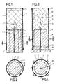
- the table lamp shown in FIGS. 1 and 2 has a candle (1) with a wick (2) arranged centrally in it, which can burn with an open flame (3).
- a wick (2) arranged centrally in it, which can burn with an open flame (3).
- vertically extending wedge-shaped ribs (5) are arranged offset at the same angular distance from one another, as shown in particular in FIG.
- a cover (6) which is cylindrical in plan is attached from above. It largely encloses the candle (1), which is shown in FIG. 1.
- the ribs (5) keep the casing (6) at a concentric distance from the candle (1) and in particular the wick (2) arranged centrally therein, so that the flame (3) is more or less normal The position of the lamp cannot come into contact with the inside of the cover (6).
- the sheath (6) consists of a cylindrical jacket (7), which is knitted, woven, braided, crocheted or otherwise formed from an open-mesh or lattice-like, flame-retardant and fire-resistant thread material. At the two ends of the sheath (6) there is an end ring (8) attached to each.
- Figure 1 shows that the sheath (6) is not completely slipped over the candle (1), but ends a few millimeters above the lower end of the candle (1). This ensures that liquid wax which may flow off the candle can run off to the side and does not come into contact with the casing (7) of the casing (6).
- the cover (6) can be removed beforehand.
- the hot rising air in the casing (6) emanating from the flame (3) creates a chimney effect, so that fresh air is drawn in from all sides through the openings in the mesh-like casing (7) of the casing (6) is sucked in at the same time and rises with the hot rising combustion air.
- the flame (3) is stabilized so that it does not flicker or flicker when there is normal air turbulence in a room. This results in perfect combustion, which practically prevents the emission of soot.
- a candle (9) which has two laterally projecting shoulders (10 and 11) at the lower end.
- These paragraphs (10 and 11) are, as Figure 4 shows, formed as laterally projecting tongues.
- the tongue-like heels (10) are shorter than the tongue-shaped heels (11) and serve to center the lower end of an attached or put-on sleeve (6), so that the jacket (7) made of refractory knitted or mesh fabric cannot come into contact with the burning candle and in particular not with the flame (3) thereof.
- a closing ring (8) is again provided at the upper and lower ends of the casing (6).
- asterisks (13) are attached as decoration elements in the upper region of the casing (6), which are made of paper, metal and the like. can exist. These decorations can be chosen freely.
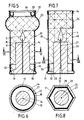
- a candle (14) with a central wick (15) is provided, the candle having a circumferential and laterally projecting reinforcement (16) at the lower end.
- the candle (14) is inserted into a base (17) made of metal, plastic, ceramic or the like.
- the pedestal (17) has a lower, outwardly circumferential, bead-shaped foot section (18) and a neck-shaped cylindrical collar (19), which projects upwards from this, onto which an essentially cylindrical sleeve (20) is attached from above and thus from it can be kept concentric to the candle (14).
- the sheath (20) consists of a largely cylindrical jacket (21), which is constructed from mesh-like or lattice-like, flame-retardant and non-combustible material, such as a knitted fabric, braid, knitted fabric, fabric or other network made of fiberglass or glass wool fibers can be.
- a knitted fabric, braid, knitted fabric, fabric or other network made of fiberglass or glass wool fibers can be.
- an end ring (22) which gives the casing a certain stability.
- the cover (20) or its jacket (21) near the upper end is provided with a bead-like widening (23) for decorative reasons.
- an annular container (24) is suspended, in which there is an absorbent insert (25) which can be used to absorb fragrance or, for example, also a volatile mosquito repellent and consists, for example, of glass wool.
- the hot air rising inside the casing (20) heats the container (24) and thus the absorbent insert (25) in it, so that the liquid medium in the container or insert gradually evaporates and thus evaporates .
- dripping candle wax can be caught by the base (17). This also ensures that this wax cannot come into contact with the casing (21) of the casing (20), so that it cannot clog its openings either.
- FIGS. 7 and 8 The embodiment shown in FIGS. 7 and 8 is a lamp in which a series-produced candle (26) with a molded-in wick (27) is used.
- a pointed mandrel (29) is attached to the bottom of a bowl-shaped base (28) which is hexagonal in plan, onto which the candle (26) is inserted so that it is located centrally in the base (28).
- a sleeve (30) which can be detachably attached to the base (28) and which, in accordance with the shape of the base, has a hexagonal plan, as shown in particular in FIG.
- the base (28) has a bead-shaped, outwardly projecting extension (31) at the lower end, on which the attached cover (30) rests with its lower end, as shown in FIG. From the extension (31) a hexagonal collar (32) leads practically vertically upwards, which supports the lower end of the attached cover (30) and thus ensures that the attached cover (30) is perpendicular and concentric to the candle (26) stands so that its flame (3) cannot come into contact with the jacket (33).
- the base (28), as shown in FIG. 7, is bowl-shaped and serves to catch any molten wax of the candle (26) that may run down.
- the sleeve (30) is also provided with an end ring (34) at the upper and lower ends in this embodiment. Between the two ends of the casing (30) there is also a further ring (35) intended for decorative purposes, which can be slidably seated on the casing (30) and carries, for example, decorative images and / or contains decorative openings.
- the jacket (33) of the casing (30) consists of a plurality of openings in the form of mesh-like or lattice-shaped, flame-retardant and non-combustible material, similar to the previously described embodiments.
- a commercially available tea light (36) is used as the light source.
- This tea light (36) is inserted into a bowl-shaped base (37) with a raised edge (38) so that it cannot slip sideways.
- a circular (and thus overall cylindrical) shell (39) is placed on the base (37)
- Figures 9 and 10 experience no lateral support because the shell (39) is secured against slipping sideways by the upstanding wall (40) of the tea light (35) inserted into the base (37).
- the casing (42) of the casing (39) consists of mesh or lattice-shaped material of the type explained in detail above.
- an end ring (32) stabilizing the casing similar to the previously explained exemplary embodiments.
- the holder is designed as a container (43) and provided with a lid (44). Both parts of the holder or stand are made of refractory material such as glass, metal or the like.
- the lid (44) contains a central opening for a wick (45), at the outer end of which an open flame (3) can burn.
- the container (43) contains liquid fuel (46) such as petroleum, paraffin oil or the like, which is sucked out by the wick hanging into the container (43) and fed to the flame (3) burning centrally above the cover (44).
- the container (43) has a central cylindrical collar (47) and a bead-shaped foot (48) projecting radially above the collar.
- a bottle-shaped envelope (49) shaped like the glass cylinder of a known petroleum lamp is placed on the collar (47) of the container (44), the enlarged lower end (50) of which is on the cylindrical collar (47) of the container ( 43) sits and is centered by it.
- the mesh-like or lattice-like material forming the jacket of the respective sleeve which can be made luminous by the light source located inside the sleeve, can be designed in a variety of decorative ways, for example Christmas motifs, zodiac signs, Wear flowers, animal figures, advertisements and other emblems. This results in a versatile use and application of the lamp according to the invention, which can be used both in closed rooms and, with a corresponding design, outdoors.
- the lamp in turn has a commercially available candle (53) or candle (53) with a centrally arranged wick (54), which can also burn with an open flame (3).
- the candle (53) is inserted into a base (55) serving as a holder, which in the exemplary embodiment shown has four ribs (56) running to the center of the base, which are distributed at a uniform distance from one another over the circumference of the base (55) which is circular in plan are arranged.
- the ribs (56) have angular recesses (57) directed towards the center of the base (55) and stepped front ends (58) which are spaced apart from one another and are dimensioned such that candles of different diameters are inserted into the base (55) can be inserted.
- a candle (53) with an outer diameter of 40 mm is inserted into the base (55), the lower end of which rests on the recesses (57) of the ribs (56).
- a candle with a diameter of 20 mm can also be inserted, which fits between the ends (58) of the ribs (56).
- a tea light with a diameter of about 40 mm also fits into the lamp according to FIGS. 13 and 14. Such a tea light, like the candle (53) shown in the drawing, would rest on the angular recesses (57) of the ribs (56).
- the lamp according to FIGS. 13 and 14 is provided with a cylindrical shell (59) which is attached to the base (55) and is centered by the outer edges of the ribs (56) opposite the inserted candle (53).
- the casing (16) of the casing (59) in this case also consists of a mesh or grid-like, flame-retardant and fire-resistant material, although the casing, as in the previously described embodiments, is non-flammable.
- end rings (61) which also serve to stabilize the casing.
- the flame (3) is otherwise covered and thus protected by the sleeve (62) made of foil material, in this embodiment there is also a calm and therefore soot-free combustion even with strong air drafts from outside, for example in the wind, so that the lamp 13 and 14 is also suitable for outdoor use.
- a candle (63) with a wick (65) arranged centrally therein is arranged in an essentially conical envelope (66).
- the taper of the casing (67) of the casing (66) is chosen so that the flame (3) of the candle (64) cannot come into contact with the casing (67), even if the lamp is not exactly vertical.
- the jacket (67) also consists of a mesh-like or lattice-like flame-retardant and non-combustible material.
- an end ring (68) is arranged on the outside of the casing.
- a two-part base (72) is provided as the holder.
- the base (72) has an outer shell (73) serving as a foot and thus as a support, with an edge (74) projecting radially outwards and a raised, essentially cylindrical neck (75) which the attached sleeve (66) is centered opposite the candle (64).
- the lower end of the sleeve lies on the radially projecting edge (74).
- a raised hollow socket (76) which serves to receive a socket (77) into which the candle (64) is inserted, as shown in particular in FIG.
- the socket (77) is provided with a pin (78) which fits into the socket (76) and is inserted into it.
- FIG. 14 and FIG. 16 show that there is a sufficient distance (79 or 80) between the casing (59 or 66) and the candle (63 or 64) so that any wax material overflowing over the outer edge of the candle (63 or 64) can flow down and collect within the base (55 or 72) without touching the jacket (60 or 67) of the relevant shell, so that the jacket or its openings are not covered by flowing candle material such as Wax can become clogged.
- the base for candle and cover serves as a holder of the lamp. Fastening elements or a foot can be attached to this holder, as will be explained below with the aid of further individual examples.
- a tea light (82) with an inserted central wick (83) and wick holder (84) is inserted into a bowl-shaped lower part (81).
- the tea light burns with an open flame (3).
- the ring (85) and the flange (86) attached to it are good heat conductors, so that the ring (85) moves downward as the candle burns down and finally disappears in the shell-like lower part (81).
- the horizontal flange (86) prevents the ring (85) from sliding too deep into the lower part (81).
- the lower part (81) serving as a holder is arranged on a lamp-like foot (88).
- the shell-like lower part (81) has an inwardly circumferential collar (89), onto which a sheath (90) serving as a luminous element can be slipped so that it sits concentrically with the flame (3).
- the casing (90) has a cylindrical jacket (91) which is made of flame-resistant and non-combustible, lattice-like or mesh-like material. End rings can be provided at the top and bottom of the cylindrical shell.
- the lower end of the candle (82) is located in a bowl-like cup (92) which has a raised, internally conical side wall (93) which tapers upwards in cross-section and which has the ring (85 ) can record.
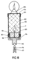
- the embodiment of the lamp shown in FIG. 18 is designed for attachment to Christmas trees.
- a clip (96) On the underside of a bowl-shaped lower part (94) serving as a holder, a clip (96) is arranged via a ball joint (95), which clip is used to attach it to a branch of a tree, not shown, such as a Christmas tree.
- a rigid needle (97) is arranged, through the branch which the clip (96) is plugged on, can be drilled through to prevent the clip (96) and thus the entire lamp from tilting away to the side.
- the lower part (94) has an upstanding cylindrical side wall (98), the upper end of which is designed as a collar (99) set back inwards.
- a sleeve (100) can be detachably attached to this collar (99), as shown in FIG. 18.
- the sheath (100) has an end ring (101) at each of the two ends and has a cylindrical jacket (102) which is made of grid-like or mesh-like, flame-retardant and non-combustible material, as in the previously explained embodiments.
- a cover (105) containing air holes (104) is slipped onto the upper end of the casing (100) and serves as a cover and as a holder for a standing upright pane provided as decoration.
- This disc can carry the image of a flame or a star.
- a bracket-shaped adjustable foot (108) is arranged on the bowl-shaped lower part (107) of the lamp, which serves to attach the lamp to the neck (109) of a vase (110).
- the foot (108) has three arms (111) which can be pivoted individually about horizontal axes and which can be pivoted inwards or outwards by means of a rotatable adjusting spindle (112), in order to use external recesses (113) if necessary to provide the outside To be able to grasp the end (114) of the neck (109) of the vase (110) in a form-fitting manner.
- the lamp contains a tea light (115) as a light source, which can burn with an open flame (3).
- the tea light is accommodated in a detachably attached cylindrical shell (116), which is constructed and constructed similarly to the shells of the above-described embodiments.
- the cylindrical sheath (117) contains ribs (118) running over its entire length, which are made of refractory material and are used to center a long candle (119) with a central wick (120).
- End rings (121) are located at the upper and lower ends of the shell, which in turn is provided with a lattice or mesh-like casing. This embodiment is particularly suitable for church candles that are very long and therefore burn long.
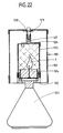
- a bowl-shaped lower part (122) of the lamp is provided with a vase-like foot (123).
- a tea light (124) which can burn with an open flame (3), is inserted into the lower part (122) as the light source.
- a bearing pin (129) is inserted into the upper socket-like end of the pin (127) containing the bearing cap (128), which serves as a counter bearing and rotatably supports a cylindrical sleeve (130), the jacket (131) of which consists of stiffened lattice-like or mesh-like material , which is flame-retardant and non-flammable.
- the cover (130) can carry decorative motifs or can be provided with such motifs.
Landscapes
- Engineering & Computer Science (AREA)
- General Engineering & Computer Science (AREA)
- Arrangement Of Elements, Cooling, Sealing, Or The Like Of Lighting Devices (AREA)
- Non-Portable Lighting Devices Or Systems Thereof (AREA)
- Fastening Of Light Sources Or Lamp Holders (AREA)
Applications Claiming Priority (4)
| Application Number | Priority Date | Filing Date | Title |
|---|---|---|---|
| DE19893901836 DE3901836A1 (de) | 1989-01-23 | 1989-01-23 | Leuchtgitterkerze |
| DE3901836 | 1989-01-23 | ||
| DE3912913 | 1989-04-20 | ||
| DE3912913A DE3912913A1 (de) | 1989-01-23 | 1989-04-20 | Leuchtgitterkerze |
Publications (2)
| Publication Number | Publication Date |
|---|---|
| EP0381006A2 true EP0381006A2 (fr) | 1990-08-08 |
| EP0381006A3 EP0381006A3 (fr) | 1990-08-29 |
Family
ID=25877031
Family Applications (1)
| Application Number | Title | Priority Date | Filing Date |
|---|---|---|---|
| EP90101250A Withdrawn EP0381006A3 (fr) | 1989-01-23 | 1990-01-23 | Lampe, en particulier lampe de table |
Country Status (3)
| Country | Link |
|---|---|
| EP (1) | EP0381006A3 (fr) |
| CA (1) | CA2008273A1 (fr) |
| DE (1) | DE3912913A1 (fr) |
Cited By (6)
| Publication number | Priority date | Publication date | Assignee | Title |
|---|---|---|---|---|
| DE19625247A1 (de) * | 1996-06-24 | 1998-01-02 | Blaurock Andreas Dipl Agr Ing | Öllampe als Aufsatz auf gebräuchliche Weinflaschen |
| GB2412426A (en) * | 2004-03-25 | 2005-09-28 | Michaela Teresa Yates | A Candle and an Associated Candleholder, and a Method of Making the Candle in the Candleholder |
| WO2011093803A1 (fr) * | 2010-01-27 | 2011-08-04 | Pax D.O.O. | Boîtier de bougie modulaire |
| WO2017097435A1 (fr) * | 2015-12-10 | 2017-06-15 | Regina Peitzmeier | Godet de bougie et bougie munie d'un godet de bougie |
| CN107687691A (zh) * | 2017-08-11 | 2018-02-13 | 深圳市润隆电子有限公司 | 一种多功能空气加湿器 |
| DE202021103639U1 (de) | 2021-07-06 | 2022-10-18 | Aiven Abu-Ghazaleh | Windlicht mit verschraubbarem Bodenteil |
Family Cites Families (5)
| Publication number | Priority date | Publication date | Assignee | Title |
|---|---|---|---|---|
| CH182883A (de) * | 1935-03-12 | 1936-02-29 | Achermann Anton | Vorrichtung zum Verhindern des Abtropfens von brennenden Kirchenkerzen. |
| US2659809A (en) * | 1950-06-29 | 1953-11-17 | Melia Earl Paul | Electric lamp shade |
| DE2449175A1 (de) * | 1974-10-16 | 1976-04-22 | Helmut Zanker | Kerzenhalter |
| FR2309792A1 (fr) * | 1975-01-09 | 1976-11-26 | Mevorah Marco | Diffuseur de lumiere |
| DE8801661U1 (de) * | 1988-02-10 | 1988-03-24 | Netzer, Karl, 6143 Lorsch | Becher für Teelichter, Opferlichter, Grablichter und Partylichter zur Aufnahme von gepreßtem, flüssigem und halbflüssigem Paraffin mit mittigem Docht |
-
1989
- 1989-04-20 DE DE3912913A patent/DE3912913A1/de not_active Ceased
-
1990
- 1990-01-22 CA CA002008273A patent/CA2008273A1/fr not_active Abandoned
- 1990-01-23 EP EP90101250A patent/EP0381006A3/fr not_active Withdrawn
Cited By (8)
| Publication number | Priority date | Publication date | Assignee | Title |
|---|---|---|---|---|
| DE19625247A1 (de) * | 1996-06-24 | 1998-01-02 | Blaurock Andreas Dipl Agr Ing | Öllampe als Aufsatz auf gebräuchliche Weinflaschen |
| DE19625247C2 (de) * | 1996-06-24 | 2000-11-02 | Blaurock Werner | Öllampe als Aufsatz auf eine Weinflasche |
| GB2412426A (en) * | 2004-03-25 | 2005-09-28 | Michaela Teresa Yates | A Candle and an Associated Candleholder, and a Method of Making the Candle in the Candleholder |
| GB2412426B (en) * | 2004-03-25 | 2006-10-18 | Michaela Teresa Yates | Candle Assemblies |
| WO2011093803A1 (fr) * | 2010-01-27 | 2011-08-04 | Pax D.O.O. | Boîtier de bougie modulaire |
| WO2017097435A1 (fr) * | 2015-12-10 | 2017-06-15 | Regina Peitzmeier | Godet de bougie et bougie munie d'un godet de bougie |
| CN107687691A (zh) * | 2017-08-11 | 2018-02-13 | 深圳市润隆电子有限公司 | 一种多功能空气加湿器 |
| DE202021103639U1 (de) | 2021-07-06 | 2022-10-18 | Aiven Abu-Ghazaleh | Windlicht mit verschraubbarem Bodenteil |
Also Published As
| Publication number | Publication date |
|---|---|
| EP0381006A3 (fr) | 1990-08-29 |
| CA2008273A1 (fr) | 1990-07-23 |
| DE3912913A1 (de) | 1990-10-25 |
Similar Documents
| Publication | Publication Date | Title |
|---|---|---|
| DE4203644A1 (de) | Dauerbrenn-licht | |
| DE60013460T2 (de) | Geheizte vorrichtung zur abgabe von flüchtigen stoffen | |
| EP0093251A2 (fr) | Distributeur de produit odoriférant | |
| DE4314122A1 (de) | Dauerbrenn-Licht | |
| EP0381006A2 (fr) | Lampe, en particulier lampe de table | |
| DE102023205512B4 (de) | Brennstoffbehälter für ein Tischfeuer | |
| DE3901836A1 (de) | Leuchtgitterkerze | |
| DE9001271U1 (de) | Windlicht od.dgl. | |
| WO2005022035A1 (fr) | Photophore | |
| DE1958724C3 (de) | Kerzenförmiger Leuchtkörper | |
| AT509247A2 (de) | Dochtkörper als dochtkrone | |
| DE8205399U1 (de) | Beleuchtungskoerper | |
| WO2024175276A1 (fr) | Réservoir de combustible pour un foyer de table | |
| EP3682164A1 (fr) | Lampe à combustion, en particulier lanterne et sa suspension | |
| DE934284C (de) | Kerzenhalter, insbesondere in Gestalt einer Lichtrose | |
| DE20004848U1 (de) | Kerze/Fackel ohne abbrennbaren Docht | |
| DE934285C (de) | Kerzenhalter fuer Dekorationszwecke, insbesondere in Form einer Blume | |
| DE9416788U1 (de) | Windlicht aus Edelstahl und Glas | |
| DE463232C (de) | Blaubrenner mit einer den oberen Teil des Dochts zum Teil umschliessenden Begrenzungsscheibe | |
| DE9401721U1 (de) | Lichtquelle für dekorative Zwecke | |
| DE37895C (de) | Kerzenhalter für Laternen und Leuchter | |
| DE637994C (de) | Kerzenhuelse | |
| DE9302084U1 (de) | Duftleuchte mit wenigstens einem Schirm | |
| DE4017383A1 (de) | Windlicht oder dergleichen | |
| DE20208541U1 (de) | Anordnung, bestehend aus einer Kombination einer Einrichtung zum Abbrennen von Räucherkegeln, einer Licht- und/oder Wärmequelle und/oder wenigstens einem Verdampfungsgefäß |
Legal Events
| Date | Code | Title | Description |
|---|---|---|---|
| PUAI | Public reference made under article 153(3) epc to a published international application that has entered the european phase |
Free format text: ORIGINAL CODE: 0009012 |
|
| PUAL | Search report despatched |
Free format text: ORIGINAL CODE: 0009013 |
|
| AK | Designated contracting states |
Kind code of ref document: A2 Designated state(s): CH DE FR GB IT LI NL SE |
|
| AK | Designated contracting states |
Kind code of ref document: A3 Designated state(s): CH DE FR GB IT LI NL SE |
|
| 17P | Request for examination filed |
Effective date: 19901123 |
|
| STAA | Information on the status of an ep patent application or granted ep patent |
Free format text: STATUS: THE APPLICATION IS DEEMED TO BE WITHDRAWN |
|
| 18D | Application deemed to be withdrawn |
Effective date: 19920801 |