EP0381079A1 - Gasturbinenbrennkammer und Betriebsverfahren dafür - Google Patents
Gasturbinenbrennkammer und Betriebsverfahren dafür Download PDFInfo
- Publication number
- EP0381079A1 EP0381079A1 EP90101599A EP90101599A EP0381079A1 EP 0381079 A1 EP0381079 A1 EP 0381079A1 EP 90101599 A EP90101599 A EP 90101599A EP 90101599 A EP90101599 A EP 90101599A EP 0381079 A1 EP0381079 A1 EP 0381079A1
- Authority
- EP
- European Patent Office
- Prior art keywords
- chamber
- sub
- combustion
- fuel
- gas turbine
- Prior art date
- Legal status (The legal status is an assumption and is not a legal conclusion. Google has not performed a legal analysis and makes no representation as to the accuracy of the status listed.)
- Granted
Links
Images


Classifications
-
- F—MECHANICAL ENGINEERING; LIGHTING; HEATING; WEAPONS; BLASTING
- F02—COMBUSTION ENGINES; HOT-GAS OR COMBUSTION-PRODUCT ENGINE PLANTS
- F02C—GAS-TURBINE PLANTS; AIR INTAKES FOR JET-PROPULSION PLANTS; CONTROLLING FUEL SUPPLY IN AIR-BREATHING JET-PROPULSION PLANTS
- F02C9/00—Controlling gas-turbine plants; Controlling fuel supply in air- breathing jet-propulsion plants
- F02C9/26—Control of fuel supply
- F02C9/32—Control of fuel supply characterised by throttling of fuel
- F02C9/34—Joint control of separate flows to main and auxiliary burners
-
- F—MECHANICAL ENGINEERING; LIGHTING; HEATING; WEAPONS; BLASTING
- F02—COMBUSTION ENGINES; HOT-GAS OR COMBUSTION-PRODUCT ENGINE PLANTS
- F02C—GAS-TURBINE PLANTS; AIR INTAKES FOR JET-PROPULSION PLANTS; CONTROLLING FUEL SUPPLY IN AIR-BREATHING JET-PROPULSION PLANTS
- F02C7/00—Features, components parts, details or accessories, not provided for in, or of interest apart form groups F02C1/00 - F02C6/00; Air intakes for jet-propulsion plants
- F02C7/26—Starting; Ignition
-
- F—MECHANICAL ENGINEERING; LIGHTING; HEATING; WEAPONS; BLASTING
- F23—COMBUSTION APPARATUS; COMBUSTION PROCESSES
- F23R—GENERATING COMBUSTION PRODUCTS OF HIGH PRESSURE OR HIGH VELOCITY, e.g. GAS-TURBINE COMBUSTION CHAMBERS
- F23R3/00—Continuous combustion chambers using liquid or gaseous fuel
- F23R3/02—Continuous combustion chambers using liquid or gaseous fuel characterised by the air-flow or gas-flow configuration
- F23R3/16—Continuous combustion chambers using liquid or gaseous fuel characterised by the air-flow or gas-flow configuration with devices inside the flame tube or the combustion chamber to influence the air or gas flow
-
- F—MECHANICAL ENGINEERING; LIGHTING; HEATING; WEAPONS; BLASTING
- F23—COMBUSTION APPARATUS; COMBUSTION PROCESSES
- F23R—GENERATING COMBUSTION PRODUCTS OF HIGH PRESSURE OR HIGH VELOCITY, e.g. GAS-TURBINE COMBUSTION CHAMBERS
- F23R3/00—Continuous combustion chambers using liquid or gaseous fuel
- F23R3/02—Continuous combustion chambers using liquid or gaseous fuel characterised by the air-flow or gas-flow configuration
- F23R3/26—Controlling the air flow
-
- F—MECHANICAL ENGINEERING; LIGHTING; HEATING; WEAPONS; BLASTING
- F23—COMBUSTION APPARATUS; COMBUSTION PROCESSES
- F23R—GENERATING COMBUSTION PRODUCTS OF HIGH PRESSURE OR HIGH VELOCITY, e.g. GAS-TURBINE COMBUSTION CHAMBERS
- F23R3/00—Continuous combustion chambers using liquid or gaseous fuel
- F23R3/28—Continuous combustion chambers using liquid or gaseous fuel characterised by the fuel supply
- F23R3/34—Feeding into different combustion zones
-
- F—MECHANICAL ENGINEERING; LIGHTING; HEATING; WEAPONS; BLASTING
- F05—INDEXING SCHEMES RELATING TO ENGINES OR PUMPS IN VARIOUS SUBCLASSES OF CLASSES F01-F04
- F05D—INDEXING SCHEME FOR ASPECTS RELATING TO NON-POSITIVE-DISPLACEMENT MACHINES OR ENGINES, GAS-TURBINES OR JET-PROPULSION PLANTS
- F05D2270/00—Control
- F05D2270/30—Control parameters, e.g. input parameters
- F05D2270/31—Fuel schedule for stage combustors
Definitions
- the present invention relates to a gas turbine combustor and, more particularly, to a gas turbine combustor which is partly of diffusion type and partly of premixed type.
- exhaust emissions from a gas turbine combustor contain substances such as NOx, CO, UHC (unburnt hydrocarbon) and the like which are causes of air pollution.
- NOx is under a strict control by regulations, and various methods have been proposed for reducing emission of NOx.
- wet-type NOx generation reducing method water or steam is sprayed into a combustor. This method, however, is inevitably accompanied by a reduction in the efficiency of the gas turbine plant. Therefore, in recent years, a method known as dry-type NOx generation reducing method is becoming a major method.
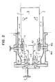
- the combustor has a cylindrical combustion sleeve 7 which is divided into two sections in the longitudinal direction thereof so as to define a sub-chamber 1 which is formed in an upstream side (left-hand side in Fig. 2) and intended for a first-stage combustion and a main chamber 2 which is formed in a downstream side and intended for a second-stage combustion.
- a first-stage fuel nozzle (referred to as "F1 fuel nozzle” hereinafter) 3 is disposed in a region near the upstream end of the sub-chamber 1.
- This fuel nozzle 3 is of a diffusion type combustion in which the fuel 30 injected therefrom is diffused in the surrounding air c so as to be burnt with the air c .
- An air swirler 4 is disposed at the end 22 of the main chamber 2 of the second stage.
- the fuel 32 discharged from a second-stage fuel nozzle (referred to as "F2 fuel nozzle” hereinafter) 5 is premixed with air n within the air swirler 4 so as to perform premixed combustion at the outlet of the air swirler 4.
- Fig. 3 is a graph showing the characteristics of generation of NOx both in the diffusion combustion and premixed combustion, wherein the axis of abscissa represents the fuel-to-air ratio and the axis of ordinate represents the NOx content in relative value.
- the stoichiometric fuel-to-air ratio for methane gas is 0.058 and the gas turbine combustor is usually operated with a fuel-to-air ratio which is below this stoichiometric value.
- the fuel-to-air ratio at rated operation was in a range of around 0.04. Since the diffusion combustion is partly employed in this system, the NOx characteristic of this system exhibits such a tendency that the change in relative value of NOx content is comparatively small even if the fuel-to-air ratio is changed. Further, as shown in Fig.
- the conventional combustor designed for reduced NOx emission is a so-called hybrid combustor in which these diffusion and premixed combustions are combined and, in operation thereof, the diffusion combustion alone is used while the load level is still low after the start-up of the gas turbine and the premixed combustion and the diffusion combustion are simultaneously used in the load range between a light load and a rated load.
- the flame in the sub-chamber 1 is the diffusion combustion flame
- the flame in the main chamber 2 is the premixed combustion flame.
- Conventional hybrid combustor employs an internal air flow rate control mechanism as indicated by IFC in Fig. 3 for the purpose of controlling the fuel-to-air ratio, in order to expand the region of the premixed combustion flame in the main chamber.
- IFC internal air flow rate control mechanism
- the regulations on reduction in NOx content was not so strict, so that a simple two-staged combustion with a mere addition of premixed combustion zone (F2 fuel flame) could satisfy such regulations.
- F2 fuel flame premixed combustion zone
- the regulations on reduction in NOx content is becoming strict year by year and, to meet such a demand, it has become necessary to effectively reduce generation of NOx also in the first stage, i.e., in the diffusion combustion zone (F1 fuel flame).
- Fig. 4 is a graph showing a characteristic of change in the fuel-to-air ratio in relation to the rotation speed of the gas turbine and the level of the load on the gas turbine. More specifically, in this Figure the axis of abscissa represents the rotation speed and the load level, while the axis of ordinate represents the fuel-to-air ratio. Ignition of the fuel is done when the gas turbine rotation speed is 16% of the rated speed and acceleration of the gas turbine is commenced after a period of warm-up which usually continues several minutes from the ignition. The fuel-to-air ratio drastically increases and reaches its peak during the acceleration. The fuel-to-air ratio is then progressively decreased and becomes minimum when the gas turbine has been accelerated to the rated speed under no load.
- the fuel-to-air ratio then starts to increase again in accordance with an increase in the load level and is maximized immediately before the rated load is reached.
- the F1 fuel nozzle 3 (see Fig. 2) is used from the start-up of the gas turbine until the load increases to about 30% of the load under the rated speed, and injects a large amount of the fuel during acceleration of the gas turbine.
- a shortage in oxygen takes place in the region around the F1 fuel nozzle 3 because the space is restricted in this region, so that the flame from the F1 fuel nozzle 3 (F1 fuel flame) tends to blow off towards the main chamber having a comparatively large space with the result that the flame is extinguished or blown off as a result of contact with cold air.
- the rotation speed of the gas turbine at which the blow off of the flame takes place has a certain relation to the temperature of the air discharged from the gas turbine and, needless to say, the blow off or extinguishment of flame is retarded as the air temperature is raised.
- Fig. 5 is a graph showing the relationship between fuel flow rate (axis of ordinate) and gas turbine rotation speed (axis of abscissa).
- a gas turbine operation curve represents the state of operation of the gas turbine as determined by the gas turbine rotation speed and the fuel flow rate.
- a mark X on this curve represents a point at which the flame is blown off. In the illustrated case, the blow off of the flame takes place when the rotation speed is comparatively low.
- a curve representing the upper limit against the blow off of the flame is obtained by connecting a plurality of such points of blow off. Similarly, there is a curve representing the lower limit against blow off of the flame.
- the conventional art mentioned above has been very effective for reducing the NOx generation, but with respect to the quick start-up of the gas turbine it has a disadvantage in that during the start-up the blow off of the flame takes place or a very long time is required until the rated rotation speed is reached although the flame is not blown off.
- an object of the present invention is to provide a gas turbine combustor which enables a gas turbine to be started up in a desired short time.
- Another object of the present invention is to provide a gas turbine combustor which can effectively stabilize the diffusion flame of F1 fuel during start-up.
- Still another object of the present invention is to provide a method of operating a gas turbine combustor which enables the gas turbine to be started up in a short time.
- a gas turbine combustor comprising a combustion sleeve, a combustion sub-chamber disposed in an upstream side of the combustion sleeve and having an air and fuel supply system, and a combustion main chamber disposed in a downstream side of the sub-chamber and having an air and fuel supply system, and formed in such a manner that the start-up of the gas turbine is effected by the hot combustion gas generated in the sub-chamber, characterized in that there is provided in the sub-chamber with a fuel nozzle for injecting the fuel during a change in the gas turbine rotation speed.
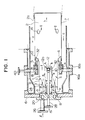
- Fig. 1 shows in section an embodiment of the gas turbine combustor of the present invention.
- the combustor is composed mainly of the following parts: i.e., a combustion sleeve 7; outer cylinders 16a and 16b surrounding the combustion sleeve 7; an end cover 6; a main chamber wall 2a forming a combustion main chamber 2; a sub-chamber wall 1a forming a combustion sub-chamber 1; an F1 fuel nozzle 3 disposed in an upstream side (left-hand side in Fig. 1) of the sub-chamber 1; and an F2 fuel nozzle 5 disposed in an upstream side of the main chamber 2.
- the sub-chamber 1 formed in an upstream side of the combustion sleeve 7 has a diameter smaller than that of the main chamber 2 disposed in its downstream side and is used for burning an F1 fuel supplied to an upstream side of the sub-chamber 1.
- the main chamber 2 disposed in a downstream side of the combustion sleeve 7 has a diameter greater than that of the sub-chamber 1 and is used for burning an F2 fuel 32 supplied from a downstream side of the sub-chamber 1 (upstream side of the main chamber 2) and combustible substances such as CO, etc. which remained unburnt in the sub-chamber 1.
- the main chamber 2 is provided at its downstream side with diluting air ports 14 which allow air g to flow into the main chamber 2 to thereby lower the temperature of the combustion gas h to a predetermined level.
- the gas turbine combustor of the present invention employs a three-staged fuel supply system: namely, the F1 fuel nozzle 3 for combustion mainly in the sub-chamber 1, the F2 fuel nozzle 5 for combustion in the main chamber 2, and an F s fuel nozzle 12 used during start-up of the gas turbine.
- the supply of air to the F1 fuel nozzle 3 is conducted as indicated by arrows a and c
- the supply of air to the F2 fuel nozzle 5 is conducted as indicated by arrows a and n .
- the supply of air to the F s fuel nozzle 12 is conducted as indicated by arrows a , b , d and e .
- the F1 fuel nozzles 3 are individually inserted into the sub-chamber 2 through the end cover 6, while a number of F2 fuel nozzles 5 are fixed to a joint portion between the sub-chamber 1 and the main chamber 2 while being arranged at a suitable circumferential pitch.
- an air swirler 4 is disposed in the space between the main chamber 2 and the sub-chamber 1, and a fuel reservoir tube 18 is connected to upstream side of the air swirler 4.
- the fuel reservoir tube 18 is supplied with the fuel through an external fuel supply tube 40.
- a number of F2 fuel nozzles 5 in the downstream side of the fuel reservoir tube 18 are arranged at a suitable circumferential pitch while being protruded into the air swirler 4.
- An inner sleeve 10 is disposed coaxially with the sub-chamber 1.
- the F s fuel nozzle 12 is disposed on the downstream end of the inner sleeve 10 coaxially therewith.
- the F s fuel nozzle 12 injects the fuel at a region which is slightly upstream of the F2 fuel nozzle 5.
- the supply of the fuel to the F s fuel nozzle 12 is conducted through a fuel supply system which is independent from the fuel supply systems for the F1 and F2 fuel nozzles.
- a sleeve 12a is disposed on the peripheral edge of the F s fuel nozzle 12 so as to protrude into the downstream side, thereby eliminating any influence of external turbulence and thus providing a recess for maintaining the flame.
- the gas turbine combustor further has a nozzle support plate 8, an F1 fuel distribution groove 20, an air distribution plate 24, an F1 fuel supply tube 26, and an F s fuel supply tube 28.
- FIG. 6 shows a pattern of supply of the fuel.
- the F1 fuel l (see Fig. 1) is supplied and ignited to effect a cross-fire (point A).
- point A the flow rate of the F1 fuel is progressively increased, and when it approaches a flow rate corresponding to the upper limit against the blow off of the flame the flow rate of the F1 fuel l is maintained constant and, at the same time, the supply of the F s fuel m (see Fig. 1) is commenced (point B).
- the gas turbine is accelerated to a rotation speed at which the temperature of the combustion air supplied from a compressor into the combustor is high enough to maintain the operation of the gas turbine by the combustion with the F1 fuel nozzle alone.
- a rotation speed is reached, the flow rate of the F1 fuel l is increased and the flow rate of the F s fuel m is reduced (point C).
- the flow rate of the F s fuel m is reduced to zero before the gas turbine under no load is accelerated to the rated speed.
- FIGs. 7a and 7b illustrate the detail of an example of the construction of the F s fuel nozzle 12.
- This F s nozzle 12 is provided, as means for improving an ability to hold flame, with an air swirler 44 surrounding a nozzle tip 42 having eight fuel injection ports.
- the outside diameter of the air swirler 44 is selected such that the air swirler 44 just fits in the inner sleeve 10.
- the fuel gas is supplied as indicated by the arrow m and injected at a certain angle to the axis of the nozzle 12 as indicated by arrows k .
- Arrows e indicate the flow of air.
- the air cools the inner sleeve 10 and is made to swirl through the air swirler 44 so as to diffuse and be mixed with the fuel m .
- the inner sleeve 10 is surrounded by the flow of the combustion gas f formed by the F1 fuel but the F s fuel m can maintain a stable flame on the downstream of the air swirler 44 and the nozzle tip 42.
- the ignition of the F s fuel m is performed automatically by the hot combustion gas f from the F1 fuel nozzle, when the supply of the F s fuel m is commenced.
- Figs. 8a and 8b show another example of the F s fuel nozzle 12 which improves an ability to hold flame.
- a baffle sleeve 46 is provided so as to fit in the inner sleeve 10, thereby forming a stable flame of the F s fuel m independently of the hot combustion gas f which is formed by the F1 fuel and which surrounds the F s nozzle 12.
- small vortexes 48 are formed on the outer peripheral side of the baffle 46, they serve as igniting fire which continuously ignites the fuel k injected from the F s fuel nozzle 12.
- the gas turbine combustor of the present invention since there is provided in the combustion sub-chamber with an inner sleeve extending from the upstream side wall of the sub-chamber toward the downstream side thereof and there is further provided in the downstream side tip of the inner sleeve with a fuel nozzle which injects the fuel during a change in rotation speed of the gas turbine, it becomes unnecessary even during start-up acceleration of the gas turbine to increase a flow rate of the fuel supplied to a fuel nozzle for combustion in the sub-chamber, i.e. it becomes that the combustion in the sub-chamber depending on the fuel-to-air ratio does not rush into the blow off region, so that it becomes possible to stably maintain the flame in the sub-chamber and to start up the gas turbine in a short time.
Landscapes
- Engineering & Computer Science (AREA)
- Chemical & Material Sciences (AREA)
- Combustion & Propulsion (AREA)
- Mechanical Engineering (AREA)
- General Engineering & Computer Science (AREA)
Applications Claiming Priority (2)
| Application Number | Priority Date | Filing Date | Title |
|---|---|---|---|
| JP23884/89 | 1989-02-03 | ||
| JP1023884A JP2544470B2 (ja) | 1989-02-03 | 1989-02-03 | ガスタ―ビン燃焼器及びその運転方法 |
Publications (2)
| Publication Number | Publication Date |
|---|---|
| EP0381079A1 true EP0381079A1 (de) | 1990-08-08 |
| EP0381079B1 EP0381079B1 (de) | 1994-06-01 |
Family
ID=12122874
Family Applications (1)
| Application Number | Title | Priority Date | Filing Date |
|---|---|---|---|
| EP90101599A Expired - Lifetime EP0381079B1 (de) | 1989-02-03 | 1990-01-26 | Gasturbinenbrennkammer und Betriebsverfahren dafür |
Country Status (4)
| Country | Link |
|---|---|
| US (1) | US5121597A (de) |
| EP (1) | EP0381079B1 (de) |
| JP (1) | JP2544470B2 (de) |
| DE (1) | DE69009202T2 (de) |
Cited By (5)
| Publication number | Priority date | Publication date | Assignee | Title |
|---|---|---|---|---|
| US5311742A (en) * | 1991-11-29 | 1994-05-17 | Kabushiki Kaisha Toshiba | Gas turbine combustor with nozzle pressure ratio control |
| US5361576A (en) * | 1992-05-27 | 1994-11-08 | Asea Brown Boveri Ltd. | Method for operating a combustion chamber of a gas turbine |
| EP0670456A1 (de) * | 1994-03-04 | 1995-09-06 | NUOVOPIGNONE INDUSTRIE MECCANICHE E FONDERIA S.p.A. | Verbesserte Verbrennungsanlage mit niedriger Schadstoffemission für Gasturbinen |
| EP1605208A1 (de) * | 2004-06-04 | 2005-12-14 | General Electric Company | Verfahren und Vorrichtung für eine emissionsarme Energieerzeugung in einer Gasturbine |
| CN104329173A (zh) * | 2014-09-11 | 2015-02-04 | 中国科学院工程热物理研究所 | 一种燃气轮机燃料与空气混合比的控制方法及装置 |
Families Citing this family (79)
| Publication number | Priority date | Publication date | Assignee | Title |
|---|---|---|---|---|
| JP2713627B2 (ja) * | 1989-03-20 | 1998-02-16 | 株式会社日立製作所 | ガスタービン燃焼器、これを備えているガスタービン設備、及びこの燃焼方法 |
| JP2894861B2 (ja) * | 1991-04-18 | 1999-05-24 | 株式会社日立製作所 | ガスタービン燃焼器の制御装置 |
| US5235814A (en) * | 1991-08-01 | 1993-08-17 | General Electric Company | Flashback resistant fuel staged premixed combustor |
| JP2954401B2 (ja) * | 1991-08-23 | 1999-09-27 | 株式会社日立製作所 | ガスタービン設備およびその運転方法 |
| EP0540167A1 (de) * | 1991-09-27 | 1993-05-05 | General Electric Company | Gestufte Vormischbrennkammer mit niedrigem NOx-Ausstoss |
| JP3037804B2 (ja) * | 1991-12-02 | 2000-05-08 | 株式会社日立製作所 | ガスタービン燃焼器の制御方法及び制御装置 |
| JPH05203148A (ja) * | 1992-01-13 | 1993-08-10 | Hitachi Ltd | ガスタービン燃焼装置及びその制御方法 |
| US5309710A (en) * | 1992-11-20 | 1994-05-10 | General Electric Company | Gas turbine combustor having poppet valves for air distribution control |
| US5487275A (en) * | 1992-12-11 | 1996-01-30 | General Electric Co. | Tertiary fuel injection system for use in a dry low NOx combustion system |
| US5319931A (en) * | 1992-12-30 | 1994-06-14 | General Electric Company | Fuel trim method for a multiple chamber gas turbine combustion system |
| JPH06272862A (ja) * | 1993-03-18 | 1994-09-27 | Hitachi Ltd | 燃料空気混合方法およびその混合装置 |
| CA2124069A1 (en) * | 1993-05-24 | 1994-11-25 | Boris M. Kramnik | Low emission, fixed geometry gas turbine combustor |
| US5359847B1 (en) * | 1993-06-01 | 1996-04-09 | Westinghouse Electric Corp | Dual fuel ultra-flow nox combustor |
| US5623826A (en) * | 1993-07-30 | 1997-04-29 | Hitachi, Ltd. | Combustor having a premix chamber with a blade-like structural member and method of operating the combustor |
| US5406798A (en) * | 1993-10-22 | 1995-04-18 | United Technologies Corporation | Pilot fuel cooled flow divider valve for a staged combustor |
| US5402634A (en) * | 1993-10-22 | 1995-04-04 | United Technologies Corporation | Fuel supply system for a staged combustor |
| DE4416650A1 (de) * | 1994-05-11 | 1995-11-16 | Abb Management Ag | Verbrennungsverfahren für atmosphärische Feuerungsanlagen |
| DE69515931T2 (de) * | 1994-06-10 | 2000-11-02 | General Electric Co., Schenectady | Regelung einer Gasturbinenbrennkammer |
| US5415000A (en) * | 1994-06-13 | 1995-05-16 | Westinghouse Electric Corporation | Low NOx combustor retro-fit system for gas turbines |
| JP2989515B2 (ja) * | 1995-04-11 | 1999-12-13 | 三菱重工業株式会社 | ガスタービンの予混合式燃焼装置 |
| US5640841A (en) * | 1995-05-08 | 1997-06-24 | Crosby; Rulon | Plasma torch ignition for low NOx combustion turbine combustor with monitoring means and plasma generation control means |
| GB2311596B (en) * | 1996-03-29 | 2000-07-12 | Europ Gas Turbines Ltd | Combustor for gas - or liquid - fuelled turbine |
| US6122916A (en) * | 1998-01-02 | 2000-09-26 | Siemens Westinghouse Power Corporation | Pilot cones for dry low-NOx combustors |
| JP3364169B2 (ja) * | 1999-06-09 | 2003-01-08 | 三菱重工業株式会社 | ガスタービン及びその燃焼器 |
| US6871503B1 (en) * | 1999-10-20 | 2005-03-29 | Hitachi, Ltd. | Gas turbine combustor with fuel-air pre-mixer and pre-mixing method for low nox combustion |
| US6598383B1 (en) * | 1999-12-08 | 2003-07-29 | General Electric Co. | Fuel system configuration and method for staging fuel for gas turbines utilizing both gaseous and liquid fuels |
| US6474071B1 (en) * | 2000-09-29 | 2002-11-05 | General Electric Company | Multiple injector combustor |
| US6530222B2 (en) | 2001-07-13 | 2003-03-11 | Pratt & Whitney Canada Corp. | Swirled diffusion dump combustor |
| US6672073B2 (en) | 2002-05-22 | 2004-01-06 | Siemens Westinghouse Power Corporation | System and method for supporting fuel nozzles in a gas turbine combustor utilizing a support plate |
| US6761033B2 (en) * | 2002-07-18 | 2004-07-13 | Hitachi, Ltd. | Gas turbine combustor with fuel-air pre-mixer and pre-mixing method for low NOx combustion |
| US6935116B2 (en) * | 2003-04-28 | 2005-08-30 | Power Systems Mfg., Llc | Flamesheet combustor |
| US6986254B2 (en) * | 2003-05-14 | 2006-01-17 | Power Systems Mfg, Llc | Method of operating a flamesheet combustor |
| US7134287B2 (en) * | 2003-07-10 | 2006-11-14 | General Electric Company | Turbine combustor endcover assembly |
| WO2008070210A2 (en) * | 2006-06-15 | 2008-06-12 | Indiana University Research And Technology Corporation | Pilot fuel injection for a wave rotor engine |
| US8176739B2 (en) * | 2008-07-17 | 2012-05-15 | General Electric Company | Coanda injection system for axially staged low emission combustors |
| US8991192B2 (en) * | 2009-09-24 | 2015-03-31 | Siemens Energy, Inc. | Fuel nozzle assembly for use as structural support for a duct structure in a combustor of a gas turbine engine |
| EP2362143B1 (de) * | 2010-02-19 | 2012-08-29 | Siemens Aktiengesellschaft | Brenneranordnung |
| EP2551470A1 (de) * | 2011-07-26 | 2013-01-30 | Siemens Aktiengesellschaft | Verfahren zum Hochfahren einer stationären Gasturbine |
| US20130122437A1 (en) * | 2011-11-11 | 2013-05-16 | General Electric Company | Combustor and method for supplying fuel to a combustor |
| US9033699B2 (en) * | 2011-11-11 | 2015-05-19 | General Electric Company | Combustor |
| US9134023B2 (en) * | 2012-01-06 | 2015-09-15 | General Electric Company | Combustor and method for distributing fuel in the combustor |
| US20130180261A1 (en) * | 2012-01-13 | 2013-07-18 | General Electric Company | Combustor and method for reducing thermal stresses in a combustor |
| US9016039B2 (en) * | 2012-04-05 | 2015-04-28 | General Electric Company | Combustor and method for supplying fuel to a combustor |
| US9335050B2 (en) * | 2012-09-26 | 2016-05-10 | United Technologies Corporation | Gas turbine engine combustor |
| US9897317B2 (en) | 2012-10-01 | 2018-02-20 | Ansaldo Energia Ip Uk Limited | Thermally free liner retention mechanism |
| US10378456B2 (en) * | 2012-10-01 | 2019-08-13 | Ansaldo Energia Switzerland AG | Method of operating a multi-stage flamesheet combustor |
| US9347669B2 (en) | 2012-10-01 | 2016-05-24 | Alstom Technology Ltd. | Variable length combustor dome extension for improved operability |
| US20150184858A1 (en) * | 2012-10-01 | 2015-07-02 | Peter John Stuttford | Method of operating a multi-stage flamesheet combustor |
| US9631815B2 (en) * | 2012-12-28 | 2017-04-25 | General Electric Company | System and method for a turbine combustor |
| US9650959B2 (en) | 2013-03-12 | 2017-05-16 | General Electric Company | Fuel-air mixing system with mixing chambers of various lengths for gas turbine system |
| US9528444B2 (en) | 2013-03-12 | 2016-12-27 | General Electric Company | System having multi-tube fuel nozzle with floating arrangement of mixing tubes |
| US9347668B2 (en) | 2013-03-12 | 2016-05-24 | General Electric Company | End cover configuration and assembly |
| US9651259B2 (en) | 2013-03-12 | 2017-05-16 | General Electric Company | Multi-injector micromixing system |
| US9366439B2 (en) * | 2013-03-12 | 2016-06-14 | General Electric Company | Combustor end cover with fuel plenums |
| US9671112B2 (en) | 2013-03-12 | 2017-06-06 | General Electric Company | Air diffuser for a head end of a combustor |
| US9534787B2 (en) | 2013-03-12 | 2017-01-03 | General Electric Company | Micromixing cap assembly |
| US9765973B2 (en) | 2013-03-12 | 2017-09-19 | General Electric Company | System and method for tube level air flow conditioning |
| US9759425B2 (en) | 2013-03-12 | 2017-09-12 | General Electric Company | System and method having multi-tube fuel nozzle with multiple fuel injectors |
| EP3015771B1 (de) | 2014-10-31 | 2020-01-01 | Ansaldo Energia Switzerland AG | Brennkammeranordnung für eine gasturbine |
| EP3015772B1 (de) | 2014-10-31 | 2020-01-08 | Ansaldo Energia Switzerland AG | Brennkammeranordnung für eine gasturbine |
| EP3026347A1 (de) * | 2014-11-25 | 2016-06-01 | Alstom Technology Ltd | Brennkammer mit ringförmigem Wirbelkörper |
| US10465909B2 (en) * | 2016-11-04 | 2019-11-05 | General Electric Company | Mini mixing fuel nozzle assembly with mixing sleeve |
| US10890329B2 (en) | 2018-03-01 | 2021-01-12 | General Electric Company | Fuel injector assembly for gas turbine engine |
| US11300054B2 (en) * | 2018-11-08 | 2022-04-12 | Pratt & Whitney Canada Corp. | Fuel flow control system and method for engine start |
| US10935245B2 (en) | 2018-11-20 | 2021-03-02 | General Electric Company | Annular concentric fuel nozzle assembly with annular depression and radial inlet ports |
| US11073114B2 (en) | 2018-12-12 | 2021-07-27 | General Electric Company | Fuel injector assembly for a heat engine |
| US11286884B2 (en) | 2018-12-12 | 2022-03-29 | General Electric Company | Combustion section and fuel injector assembly for a heat engine |
| US11156360B2 (en) | 2019-02-18 | 2021-10-26 | General Electric Company | Fuel nozzle assembly |
| JP7307441B2 (ja) * | 2021-03-23 | 2023-07-12 | トヨタ自動車株式会社 | 燃焼器 |
| US12454909B2 (en) | 2021-12-03 | 2025-10-28 | General Electric Company | Combustor size rating for a gas turbine engine using hydrogen fuel |
| US12331932B2 (en) | 2022-01-31 | 2025-06-17 | General Electric Company | Turbine engine fuel mixer |
| US12215866B2 (en) | 2022-02-18 | 2025-02-04 | General Electric Company | Combustor for a turbine engine having a fuel-air mixer including a set of mixing passages |
| US12196422B2 (en) | 2022-05-25 | 2025-01-14 | General Electric Company | Combustor with secondary fuel nozzle in dilution fence |
| US12429220B2 (en) | 2023-06-14 | 2025-09-30 | General Electric Company | Combustion section with a primary combustor and a set of secondary combustors |
| US12152779B1 (en) | 2023-08-22 | 2024-11-26 | General Electric Company | Combustor |
| US12305571B2 (en) | 2023-08-22 | 2025-05-20 | General Electric Company | Combustor |
| EP4517173A1 (de) | 2023-09-01 | 2025-03-05 | General Electric Company | Verbrennungsabschnitt mit einer primärbrennkammer und einem satz von sekundärbrennkammern |
| US12173898B1 (en) | 2023-09-01 | 2024-12-24 | General Electric Company | Combustion section with a primary combustor and a set of secondary combustors |
| US12228286B1 (en) | 2023-09-29 | 2025-02-18 | General Electric Company | Combustion section with a primary combustion chamber and a secondary combustion chamber |
Citations (4)
| Publication number | Priority date | Publication date | Assignee | Title |
|---|---|---|---|---|
| US4173118A (en) * | 1974-08-27 | 1979-11-06 | Mitsubishi Jukogyo Kabushiki Kaisha | Fuel combustion apparatus employing staged combustion |
| US4292801A (en) * | 1979-07-11 | 1981-10-06 | General Electric Company | Dual stage-dual mode low nox combustor |
| EP0169431A1 (de) * | 1984-07-10 | 1986-01-29 | Hitachi, Ltd. | Brennkammer für eine Gasturbine |
| EP0281961A1 (de) * | 1987-03-06 | 1988-09-14 | Hitachi, Ltd. | Gasturbinenbrennkammer und Verbrennungsverfahren dafür |
Family Cites Families (6)
| Publication number | Priority date | Publication date | Assignee | Title |
|---|---|---|---|---|
| JPS59173633A (ja) * | 1983-03-22 | 1984-10-01 | Hitachi Ltd | ガスタ−ビン燃焼器 |
| JPS59202324A (ja) * | 1983-05-04 | 1984-11-16 | Hitachi Ltd | ガスタ−ビン低NOx燃焼器 |
| JPS6057131A (ja) * | 1983-09-08 | 1985-04-02 | Hitachi Ltd | ガスタ−ビン燃焼器の燃料供給方法 |
| JPS60147035A (ja) * | 1984-01-11 | 1985-08-02 | Hitachi Ltd | セラミツクス燃焼器 |
| JPS60185024A (ja) * | 1984-03-02 | 1985-09-20 | Hitachi Ltd | ガスタ−ビン燃焼器 |
| JPS6232370A (ja) * | 1985-08-03 | 1987-02-12 | Murata Mfg Co Ltd | 表面電位検出装置 |
-
1989
- 1989-02-03 JP JP1023884A patent/JP2544470B2/ja not_active Expired - Fee Related
-
1990
- 1990-01-26 DE DE69009202T patent/DE69009202T2/de not_active Expired - Lifetime
- 1990-01-26 EP EP90101599A patent/EP0381079B1/de not_active Expired - Lifetime
- 1990-01-26 US US07/470,596 patent/US5121597A/en not_active Expired - Lifetime
Patent Citations (4)
| Publication number | Priority date | Publication date | Assignee | Title |
|---|---|---|---|---|
| US4173118A (en) * | 1974-08-27 | 1979-11-06 | Mitsubishi Jukogyo Kabushiki Kaisha | Fuel combustion apparatus employing staged combustion |
| US4292801A (en) * | 1979-07-11 | 1981-10-06 | General Electric Company | Dual stage-dual mode low nox combustor |
| EP0169431A1 (de) * | 1984-07-10 | 1986-01-29 | Hitachi, Ltd. | Brennkammer für eine Gasturbine |
| EP0281961A1 (de) * | 1987-03-06 | 1988-09-14 | Hitachi, Ltd. | Gasturbinenbrennkammer und Verbrennungsverfahren dafür |
Non-Patent Citations (3)
| Title |
|---|
| PATENT ABSTRACTS OF JAPAN vol. 10, no. 29 (M-451)(2086) 05 February 1986, & JP-A-60 185024 (HITACHI LTD.) 20 September 1985, * |
| PATENT ABSTRACTS OF JAPAN vol. 9, no. 29 (M-356)(1752) 07 February 1985, & JP-A-59 173633 (HITACHI LTD.) 01 October 1984, * |
| PATENT ABSTRACTS OF JAPAN vol. 9, no. 311 (M-436)(2034) 07 December 1985, & JP-A-60 147035 (HITACHI LTD.) 11 November 1984, * |
Cited By (5)
| Publication number | Priority date | Publication date | Assignee | Title |
|---|---|---|---|---|
| US5311742A (en) * | 1991-11-29 | 1994-05-17 | Kabushiki Kaisha Toshiba | Gas turbine combustor with nozzle pressure ratio control |
| US5361576A (en) * | 1992-05-27 | 1994-11-08 | Asea Brown Boveri Ltd. | Method for operating a combustion chamber of a gas turbine |
| EP0670456A1 (de) * | 1994-03-04 | 1995-09-06 | NUOVOPIGNONE INDUSTRIE MECCANICHE E FONDERIA S.p.A. | Verbesserte Verbrennungsanlage mit niedriger Schadstoffemission für Gasturbinen |
| EP1605208A1 (de) * | 2004-06-04 | 2005-12-14 | General Electric Company | Verfahren und Vorrichtung für eine emissionsarme Energieerzeugung in einer Gasturbine |
| CN104329173A (zh) * | 2014-09-11 | 2015-02-04 | 中国科学院工程热物理研究所 | 一种燃气轮机燃料与空气混合比的控制方法及装置 |
Also Published As
| Publication number | Publication date |
|---|---|
| JPH02208417A (ja) | 1990-08-20 |
| EP0381079B1 (de) | 1994-06-01 |
| DE69009202T2 (de) | 1994-09-08 |
| JP2544470B2 (ja) | 1996-10-16 |
| DE69009202D1 (de) | 1994-07-07 |
| US5121597A (en) | 1992-06-16 |
Similar Documents
| Publication | Publication Date | Title |
|---|---|---|
| EP0381079B1 (de) | Gasturbinenbrennkammer und Betriebsverfahren dafür | |
| US4967561A (en) | Combustion chamber of a gas turbine and method of operating it | |
| US6983605B1 (en) | Methods and apparatus for reducing gas turbine engine emissions | |
| US5201181A (en) | Combustor and method of operating same | |
| US5069029A (en) | Gas turbine combustor and combustion method therefor | |
| US6826913B2 (en) | Airflow modulation technique for low emissions combustors | |
| US5813232A (en) | Dry low emission combustor for gas turbine engines | |
| US5339635A (en) | Gas turbine combustor of the completely premixed combustion type | |
| US6374615B1 (en) | Low cost, low emissions natural gas combustor | |
| KR0149059B1 (ko) | 가스터빈연소기 | |
| US6532726B2 (en) | Gas-turbine engine combustion system | |
| US4054028A (en) | Fuel combustion apparatus | |
| US5974781A (en) | Hybrid can-annular combustor for axial staging in low NOx combustors | |
| US4671069A (en) | Combustor for gas turbine | |
| US4150539A (en) | Low pollution combustor | |
| US6736338B2 (en) | Methods and apparatus for decreasing combustor emissions | |
| US4292801A (en) | Dual stage-dual mode low nox combustor | |
| JP3192055B2 (ja) | ガスタービン燃焼器 | |
| US4179881A (en) | Premix combustor assembly | |
| JP2767403B2 (ja) | ガスタービン用低NOxバーナ | |
| EP1243854A1 (de) | Brennstoffeinspritzventil | |
| JP2544515B2 (ja) | ガス燃焼器 | |
| JPS59173633A (ja) | ガスタ−ビン燃焼器 | |
| JPH09178185A (ja) | ガスタービン燃焼器 | |
| JPH10176832A (ja) | ガスタービン燃焼器 |
Legal Events
| Date | Code | Title | Description |
|---|---|---|---|
| PUAI | Public reference made under article 153(3) epc to a published international application that has entered the european phase |
Free format text: ORIGINAL CODE: 0009012 |
|
| AK | Designated contracting states |
Kind code of ref document: A1 Designated state(s): CH DE FR GB IT LI |
|
| 17P | Request for examination filed |
Effective date: 19900813 |
|
| 17Q | First examination report despatched |
Effective date: 19910925 |
|
| GRAA | (expected) grant |
Free format text: ORIGINAL CODE: 0009210 |
|
| AK | Designated contracting states |
Kind code of ref document: B1 Designated state(s): CH DE FR GB IT LI |
|
| REF | Corresponds to: |
Ref document number: 69009202 Country of ref document: DE Date of ref document: 19940707 |
|
| ITF | It: translation for a ep patent filed | ||
| ET | Fr: translation filed | ||
| PLBE | No opposition filed within time limit |
Free format text: ORIGINAL CODE: 0009261 |
|
| STAA | Information on the status of an ep patent application or granted ep patent |
Free format text: STATUS: NO OPPOSITION FILED WITHIN TIME LIMIT |
|
| 26N | No opposition filed | ||
| REG | Reference to a national code |
Ref country code: GB Ref legal event code: IF02 |
|
| PGFP | Annual fee paid to national office [announced via postgrant information from national office to epo] |
Ref country code: FR Payment date: 20081217 Year of fee payment: 20 |
|
| PGFP | Annual fee paid to national office [announced via postgrant information from national office to epo] |
Ref country code: DE Payment date: 20090219 Year of fee payment: 20 |
|
| PGFP | Annual fee paid to national office [announced via postgrant information from national office to epo] |
Ref country code: CH Payment date: 20090106 Year of fee payment: 20 Ref country code: GB Payment date: 20081229 Year of fee payment: 20 |
|
| PGFP | Annual fee paid to national office [announced via postgrant information from national office to epo] |
Ref country code: IT Payment date: 20090128 Year of fee payment: 20 |
|
| REG | Reference to a national code |
Ref country code: CH Ref legal event code: PL |
|
| REG | Reference to a national code |
Ref country code: GB Ref legal event code: PE20 Expiry date: 20100125 |
|
| PG25 | Lapsed in a contracting state [announced via postgrant information from national office to epo] |
Ref country code: GB Free format text: LAPSE BECAUSE OF EXPIRATION OF PROTECTION Effective date: 20100125 |
|
| PG25 | Lapsed in a contracting state [announced via postgrant information from national office to epo] |
Ref country code: DE Free format text: LAPSE BECAUSE OF EXPIRATION OF PROTECTION Effective date: 20100126 |