EP0381117A2 - Faraday-Rotor-Vorrichtung und optischer Schalter mit einer derartigen Vorrichtung - Google Patents
Faraday-Rotor-Vorrichtung und optischer Schalter mit einer derartigen Vorrichtung Download PDFInfo
- Publication number
- EP0381117A2 EP0381117A2 EP90101728A EP90101728A EP0381117A2 EP 0381117 A2 EP0381117 A2 EP 0381117A2 EP 90101728 A EP90101728 A EP 90101728A EP 90101728 A EP90101728 A EP 90101728A EP 0381117 A2 EP0381117 A2 EP 0381117A2
- Authority
- EP
- European Patent Office
- Prior art keywords
- faraday rotator
- yoke
- hollow yoke
- faraday
- optical switch
- Prior art date
- Legal status (The legal status is an assumption and is not a legal conclusion. Google has not performed a legal analysis and makes no representation as to the accuracy of the status listed.)
- Withdrawn
Links
Images


Classifications
-
- H—ELECTRICITY
- H03—ELECTRONIC CIRCUITRY
- H03K—PULSE TECHNIQUE
- H03K17/00—Electronic switching or gating, i.e. not by contact-making and –breaking
-
- G—PHYSICS
- G02—OPTICS
- G02F—OPTICAL DEVICES OR ARRANGEMENTS FOR THE CONTROL OF LIGHT BY MODIFICATION OF THE OPTICAL PROPERTIES OF THE MEDIA OF THE ELEMENTS INVOLVED THEREIN; NON-LINEAR OPTICS; FREQUENCY-CHANGING OF LIGHT; OPTICAL LOGIC ELEMENTS; OPTICAL ANALOGUE/DIGITAL CONVERTERS
- G02F1/00—Devices or arrangements for the control of the intensity, colour, phase, polarisation or direction of light arriving from an independent light source, e.g. switching, gating or modulating; Non-linear optics
- G02F1/01—Devices or arrangements for the control of the intensity, colour, phase, polarisation or direction of light arriving from an independent light source, e.g. switching, gating or modulating; Non-linear optics for the control of the intensity, phase, polarisation or colour
- G02F1/09—Devices or arrangements for the control of the intensity, colour, phase, polarisation or direction of light arriving from an independent light source, e.g. switching, gating or modulating; Non-linear optics for the control of the intensity, phase, polarisation or colour based on magneto-optical elements, e.g. exhibiting Faraday effect
- G02F1/092—Operation of the cell; Circuit arrangements
Definitions
- the present invention relates to a Faraday rotator device capable of changing a polarized wave plane of a light by changing current, and an optical switch comprising such a Faraday rotator device for switching the propagation direction of the light between two directions.
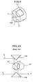
- an optical switch as shown in Fig. 10 is conventionally used.
- a prism 13 is mechanically moved back and forth to change the optical path of an incident light 5 from “a” to "b,” and from “b” to “a.”
- 12a and 12b respectively denote a total reflection prism.
- a mechanically movable portion is liable to be worn by a long period of use, leading to deviation in optical axis and thereby lowering the reliability of the apparatus.
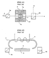
- This optical switch utilizes the principle of an optical isolator.
- a magnetic field 7a is generated, whereby a Faraday rotator 2 is magnetized.
- An incident light 5 passing through a first polarizer 6a goes into the Faraday rotator 2 in which the polarized wave plane of the light is rotated by 45°, and the light goes into a second polarizer 6b. Since the polarization direction of the second polarizer 6b is in alignment with the polarized wave plane of the light, the light can pass through it as shown by "a" in Fig. 11.
- the incident light 5 can be electromagnetically controlled in its propagation direction "a” or "b” by reversing the magnetization direction of the Faraday rotator 2.
- a Faraday rotator 2 made of a thin YIG single crystal layer formed on a substrate 9 shown in Fig. 12 (1983 General Meeting of the Communications Association, 2276, and 1983 General Meeting of the Communications Association, S13-14).
- a magnetic yoke 1 having open ends is used, and a thin layer-type Faraday rotator 2 is disposed between the open ends of the magnetic yoke 1 to provide a substantially closed magnetic circuit.
- a wire winding 3 is wound around the ring-shaped magnetic yoke 1.
- An object of the present invention is, therefore, to provide a Faraday rotator device utilizing a magneto-optic effect, which has a new magnetic circuit structure to solve the above problems.
- Another object of the present invention is to provide an optical switch comprising such a Faraday rotator device.
- the Faraday rotator device comprises (a) a Faraday rotator, (b) a wire winding encircling the Faraday rotator for changing the magnetization state of the Faraday rotator, and (c) a hollow yoke surrounding the Faraday rotator and the wire winding for forming a substantially closed magnetic circuit together with the Faraday rotator, the hollow yoke having an opening in each of front and rear walls in alignment with the Faraday rotator for permitting a light to pass through the hollow yoke and the Faraday rotator.
- the optical switch according to the present invention includes a Faraday rotator device comprising (a) a Faraday rotator, (b) a wire winding encircling the Faraday rotator for changing the magnetization state of the Faraday rotator, and (c) a hollow yoke surrounding the Faraday rotator and the wire winding for forming a substantially closed magnetic circuit together with the Faraday rotator, the hollow yoke having an opening in each of front and rear walls in alignment with the Faraday rotator for permitting a light to pass through the hollow yoke and the Faraday rotator; and a pair of polarizers disposed on front and rear sides of the Faraday rotator device, the magnetization direction of the Faraday rotator being reversible to change the optical path.
- the hollow yoke is partially or totally made of a soft magnetic material or a semi-hard magnetic material.
- Fig. 1 shows the basic structure of the optical switch according to the present invention.
- the Faraday rotator device 10 comprises a Faraday rotator 2, a wire winding 3 encircling the Faraday rotator 2 for changing the magnetization state of the Faraday rotator 2, and a hollow yoke 1 surrounding the Faraday rotator 2 and the wire winding 3 for forming a substantially closed magnetic circuit together with the Faraday rotator 2.
- the hollow yoke 1 has an opening 4a, 4b in each of front and rear walls in alignment with the Faraday rotator 2 for permitting a light to pass through the hollow yoke 1 and the Faraday rotator 2.
- the wire winding 3 is connected to lead wires (14a, 14b in Fig. 2) which extend from the yoke 1, and the current is caused to flow through the wire winding 3 to control a magnetic field applied to the Faraday rotator 2. Accordingly, the magnetization direction of the Faraday rotator 2 can easily be reversed by changing the direction of this current.
- the two polarizers 6a, 6b are at an angle of 45° relative to each other.
- the polarizer 6a is depicted such that it is rotated by 45° clockwise with respect to the optical path.
- a substantially closed magnetic circuit is formed, and it shows much smaller magnetic resistance than the conventional structure shown in Fig. 11, meaning that the Faraday rotator device of the present invention can reverse the magnetization direction of the Faraday rotator 2 with much smaller current.
- the semi-hard magnetic material has a coercive force of about 2500 A/m or less and a relatively high magnetic flux density.
- Typical examples of the semi-hard magnetic materials are as follows: 17% Ni-8% Al (Cu, Co)-bal. Fe, 10% V-50% Co-bal. Fe, 7% V-50% Co-bal. Fe, 4% V-50% Co-bal. Fe, 2% V-7.5% Cr- 52% Co-bal. Fe, 3% V-7% Cr- 52% Co-bal. Fe, Cu (1-2%)-Ti (2-3%)-Mn (11-12%)-Fe (bal.), 10% Mn-20% Co-bal. Fe, 4% V-6% Ni-45% Co-bal. Fe, 0.3% Mn-0.9% C-3% Cr-bal. Fe, 0.8% C-15% Co-4.5% Cr-bal. Fe, 30% Co- 15% Cr-bal.
- Fe 30% Co-15% (Cr+V)-bal. Fe, 3% Al-15% Ni-1% Ti-bal. Fe, 3% Cu-16% Ni-bal. Fe, 12% Fe-Nb (3-5%)-bal. Co, 10% Fe-1 .5% Be-bal. Co, Cu (17-19%)-Mn (1.5-3%)-Fe (bal.), and Fe-Cu-Mo.
- the magnetization state of the Faraday rotator 2 can be stably maintained without continuously flowing the current through the wire winding 3, whereby the polarized wave plane of a light can be maintained at either one of the two angles.
- the polarized wave plane of the light can be changed by changing the magnetic field applied to the Faraday rotator 2. And by applying a magnetic field larger than the saturation magnetization of the Faraday rotator 2 in different directions (forward and rearward directions), the Faraday rotator device can be used as an optical switch.
- the yoke When the optical switch is to be operated at a high frequency, the yoke is preferably made of a soft magnetic material such as soft ferrite with small loss. On the other hand, when the optical switch is operated in a semi-stable condition, the yoke may be made of a semi-hard magnetic material.
- a polarizer which may be used includes a beam splitter, and other double refraction prisms such as a Glan-Thompson prism, a wedge-shaped prism, etc.
- the polarizers 6a, 6b are beam splitters.
- the Faraday rotator 2 is a YIG cylindrical body through which an incident light 5 passes.
- a wire winding 3 is wound around the Faraday rotator 2 to apply a magnetic field thereto.
- a hollow yoke 1 surrounding the Faraday rotator 2 and the wire winding 3 is made of soft ferrite, and has a pair of openings 4a, 4b in front and rear side walls.
- the rotation angle of the Faraday rotator 2 is 45° at saturation.
- the polarizers 6a, 6b are beam splitters.
- the Faraday rotator 2 is a YIG cylindrical body through which an incident light 5 passes.
- a wire winding 3 is wound around the Faraday rotator 2 to apply a magnetic field to the yoke 1 and to the Faraday rotator 2.
- a hollow yoke 1 surrounding the Faraday rotator 2 and the wire winding 3 is made of an Fe-Cr-Co semi-hard magnetic material, and has a pair of openings 4a, 4b in front and rear side walls.
- the rotation angle of the Faraday rotator 2 is 45° at saturation.
- the lead wires 14a, 14b of the wire winding 3 extend from the yoke 1 and are connected to the circuit shown in Fig. 2.
- charge supplied from a power supply E via a resistor R is stored in a capacitor C (20 ⁇ F).
- the switches SW1 and SW2 are turned on to cause a discharge current having a high peak to flow through the wire winding 3 in a forward direction shown by the solid line.
- the switches SW1 and SW2 are turned off again.
- the yoke 1 made of an Fe-Cr-Co semi-hard magnetic material is magnetized in one direction (shown by 7a in Fig. 1), whereby the Faraday rotator 2 is stably magnetized in one direction.
- the light propagates in the direction "a" in Fig. 1.
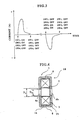
- Fig. 3 shows the discharge current which flows by turning on or off each switch in Fig. 2.
- the Faraday rotator device of the present invention shown in Fig. 1 (comprising the yoke made of an Fe-Cr-Co semi-hard magnetic material) with the conventional Faraday rotator device shown in Fig. 11, the Faraday rotator device of the present invention shows much smaller magnetic resistance than the conventional counterpart. Therefore, in the Faraday rotator device of the present invention, smaller current is sufficient to reverse the magnetization direction of the Faraday rotator 2.
- a Faraday rotator device shown in Fig. 4 was produced.
- the Faraday rotator 2 and the wire winding 3 are substantially the same as in Example 1, and the yoke 1 made of soft ferrite is constituted by two portions 1a, 1b with split surfaces 8 to facilitate the assembling of the yoke 1, the Faraday rotator 2 and the wire winding 3.
- the Faraday rotator 2 is in the shape of a cylinder in this Example, but this Faraday rotator 2 may have any cross section such as a rectangular or polygonal cross section to provide the same effects.
- the yoke 1 may have openings of any shapes. In these cases, the relations between D O and D Y shown in Fig. 5 are applicable, assuming that D O denotes a minimum size of the openings 4a, 4b of the yoke 1, and D Y denotes a maximum size of the Faraday rotator 2 in perpendicular to the optical path.
- two portions 1a, lb of the yoke 1 are divided along split surfaces 8 perpendicular to the optical path, but the hollow yoke 1 may be split in a direction parallel to the optical path.
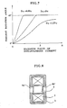
- a solid line denotes a forward direction of current (corresponding to a magnetic field 7a in Fig. 1), and a broken line denotes a rearward direction (corresponding to a magnetic field 7b in Fig. 1).
- the incident light 5 had a wavelength of about 1.55 ⁇ m for simulation of a semiconductor laser.
- the insertion loss was smaller than 1 dB in both directions, and a leakage light in an undesirable propagation direction was attenuated by more than 30 dB. Therefore, this optical switch shows excellent performance.
- the Faraday rotator device of this Example is shown in Fig. 8.
- the Faraday rotator 2 should have a large diameter, leading to a larger demagnetization coefficient. Accordingly, a large current should be flowed.
- an annular projection 4a′, 4b′ is disposed in an inner surface of an opening provided in each side wall to increase the volume of the wire winding 3.
- a hollow yoke 1 has a plurality of notches 11 on a circumferential portion.
- the temperature increase of the wire winding 3 through which current flows continuously can be somewhat suppressed by the cooling effect of flowing air.
- the notches 11 can be provided such that the yoke 1 shows substantially the same magnetic resistance in its circumferential portion and in a portion near the opening 4a, 4b, thereby minimizing the magnetic flux leaking from the surface of the yoke 1.
- the yoke 1 may be divided into a plurality of portions, some of which are made of a semi-hard magnetic material. Particularly, it is effective that only the inward annular projections 10 of the yoke 1 are made of a semi-hard magnetic material.
- the Faraday rotator was made of YIG single crystals.
- other materials such as Bi-substituted LPE (liquid phase epitaxial) layers may be used.
- LPE liquid phase epitaxial
- the LPE layer is extremely thin, a sufficient space for the wire winding cannot be provided, and even though enough space is provided, there may be a large gap between the central portion of the yoke and the LPE layer, resulting in large magnetic resistance.
- the Faraday rotator device of the present invention has a high reliability and is operable at low electric power.
- this Faraday rotator device has a hollow yoke made of a soft magnetic material, it can provide a high-performance optical switch operable at a high frequency.
- the yoke is made of a semi-hard magnetic material, the magnetization state of the Faraday rotator can be stably maintained without continuously flowing the current through the wire winding.
- Such Faraday rotator device is effective particularly for an optical switch operable at a relatively lower frequency.
Landscapes
- Physics & Mathematics (AREA)
- Nonlinear Science (AREA)
- Engineering & Computer Science (AREA)
- Power Engineering (AREA)
- General Physics & Mathematics (AREA)
- Optics & Photonics (AREA)
- Optical Modulation, Optical Deflection, Nonlinear Optics, Optical Demodulation, Optical Logic Elements (AREA)
Applications Claiming Priority (4)
| Application Number | Priority Date | Filing Date | Title |
|---|---|---|---|
| JP1021828A JPH02201419A (ja) | 1989-01-31 | 1989-01-31 | ファラデー回転素子およびこれを用いた光スイッチ |
| JP21829/89 | 1989-01-31 | ||
| JP1021829A JPH02201420A (ja) | 1989-01-31 | 1989-01-31 | ファラデー回転素子およびこれを用いた光スイッチ |
| JP21828/89 | 1989-01-31 |
Publications (2)
| Publication Number | Publication Date |
|---|---|
| EP0381117A2 true EP0381117A2 (de) | 1990-08-08 |
| EP0381117A3 EP0381117A3 (de) | 1991-07-31 |
Family
ID=26358949
Family Applications (1)
| Application Number | Title | Priority Date | Filing Date |
|---|---|---|---|
| EP19900101728 Withdrawn EP0381117A3 (de) | 1989-01-31 | 1990-01-29 | Faraday-Rotor-Vorrichtung und optischer Schalter mit einer derartigen Vorrichtung |
Country Status (3)
| Country | Link |
|---|---|
| US (1) | US5048937A (de) |
| EP (1) | EP0381117A3 (de) |
| KR (1) | KR930010691B1 (de) |
Cited By (3)
| Publication number | Priority date | Publication date | Assignee | Title |
|---|---|---|---|---|
| WO2000045214A1 (en) * | 1999-01-29 | 2000-08-03 | Tokin Corporation | Optical isolator comprising a faraday rotator |
| WO2001038930A1 (en) * | 1999-11-26 | 2001-05-31 | 3M Innovative Properties Company | Optical circuit element and method of producing the same |
| AT408700B (de) * | 1999-09-15 | 2002-02-25 | Didosyan Juri S Dr | Magnetooptisches schaltelement mit einem faraday-rotator |
Families Citing this family (27)
| Publication number | Priority date | Publication date | Assignee | Title |
|---|---|---|---|---|
| US5528415A (en) * | 1994-11-09 | 1996-06-18 | Duke University | Compact enhanced performance optical isolator using a faraday rotator |
| US5659412A (en) * | 1994-12-06 | 1997-08-19 | Lucent Technologies Inc. | Polarization diversity detection of optical signals transmitted through a polarization-mode dispersive medium |
| JP3737566B2 (ja) * | 1996-06-20 | 2006-01-18 | 富士通株式会社 | 光デバイス |
| US7170921B1 (en) * | 2002-10-18 | 2007-01-30 | Finisar Corporation | Magneto-optic variable optical attenuator |
| US20060056793A1 (en) * | 2004-02-12 | 2006-03-16 | Panorama Flat Ltd. | System, method, and computer program product for structured waveguide including nonlinear effects |
| US20050180675A1 (en) * | 2004-02-12 | 2005-08-18 | Panorama Flat Limited, A Western Australia Corporation | Apparatus, method, and computer program product for structured waveguide including performance_enhancing bounding region |
| US20050180722A1 (en) * | 2004-02-12 | 2005-08-18 | Panorama Flat Ltd. | Apparatus, method, and computer program product for structured waveguide transport |
| US20050180673A1 (en) * | 2004-02-12 | 2005-08-18 | Panorama Flat Ltd. | Faraday structured waveguide |
| US7254287B2 (en) * | 2004-02-12 | 2007-08-07 | Panorama Labs, Pty Ltd. | Apparatus, method, and computer program product for transverse waveguided display system |
| US20050185877A1 (en) * | 2004-02-12 | 2005-08-25 | Panorama Flat Ltd. | Apparatus, Method, and Computer Program Product For Structured Waveguide Switching Matrix |
| US20050180674A1 (en) * | 2004-02-12 | 2005-08-18 | Panorama Flat Ltd. | Faraday structured waveguide display |
| US20050201679A1 (en) * | 2004-02-12 | 2005-09-15 | Panorama Flat Ltd. | System, method, and computer program product for structured waveguide including modified output regions |
| US20050201654A1 (en) * | 2004-02-12 | 2005-09-15 | Panorama Flat Ltd. | Apparatus, method, and computer program product for substrated waveguided display system |
| US20060056794A1 (en) * | 2004-02-12 | 2006-03-16 | Panorama Flat Ltd. | System, method, and computer program product for componentized displays using structured waveguides |
| US20050201705A1 (en) * | 2004-02-12 | 2005-09-15 | Panorama Flat Ltd. | Apparatus, method, and computer program product for structured waveguide including recursion zone |
| US20050201698A1 (en) * | 2004-02-12 | 2005-09-15 | Panorama Flat Ltd. | System, method, and computer program product for faceplate for structured waveguide system |
| US20050201651A1 (en) * | 2004-02-12 | 2005-09-15 | Panorama Flat Ltd. | Apparatus, method, and computer program product for integrated influencer element |
| US20060056792A1 (en) * | 2004-02-12 | 2006-03-16 | Panorama Flat Ltd. | System, method, and computer program product for structured waveguide including intra/inter contacting regions |
| US20050180672A1 (en) * | 2004-02-12 | 2005-08-18 | Panorama Flat Ltd. | Apparatus, Method, and Computer Program Product For Multicolor Structured Waveguide |
| US7224854B2 (en) * | 2004-02-12 | 2007-05-29 | Panorama Labs Pty. Ltd. | System, method, and computer program product for structured waveguide including polarizer region |
| US7099547B2 (en) * | 2004-02-12 | 2006-08-29 | Panorama Labs Pty Ltd | Apparatus, method, and computer program product for structured waveguide transport using microbubbles |
| US20050180723A1 (en) * | 2004-02-12 | 2005-08-18 | Panorama Flat Ltd. | Apparatus, method, and computer program product for structured waveguide including holding bounding region |
| CN103985938B (zh) * | 2013-02-07 | 2017-03-15 | 中国计量学院 | 基于石墨烯的磁可调法拉第旋转器 |
| US8748245B1 (en) | 2013-03-27 | 2014-06-10 | Io Semiconductor, Inc. | Semiconductor-on-insulator integrated circuit with interconnect below the insulator |
| US9478507B2 (en) | 2013-03-27 | 2016-10-25 | Qualcomm Incorporated | Integrated circuit assembly with faraday cage |
| US11777220B2 (en) | 2019-07-25 | 2023-10-03 | Syght, Inc. | Light path defining apparatus and methods |
| US11378829B2 (en) | 2019-07-25 | 2022-07-05 | Syght, Inc. | Advanced spatial light modulators, associated systems and methods |
Family Cites Families (13)
| Publication number | Priority date | Publication date | Assignee | Title |
|---|---|---|---|---|
| US3492061A (en) * | 1965-06-18 | 1970-01-27 | Bell Telephone Labor Inc | Light beam deflector in which the light is diffracted by magnetic waves |
| FR1491338A (fr) * | 1966-06-01 | 1967-08-11 | Telecommunications Sa | Dispositif pour la modulation d'un rayonnement électromagnétique, en particulier d'un rayonnement laser |
| US3523718A (en) * | 1968-04-17 | 1970-08-11 | Us Army | Low temperature optical isolator for laser systems |
| US3626335A (en) * | 1969-11-10 | 1971-12-07 | Emerson Electric Co | Phase-shifting means |
| US3982213A (en) * | 1975-04-16 | 1976-09-21 | United Technologies Corporation | Monolithic reciprocal latching ferrite phase shifter |
| US4042831A (en) * | 1976-01-21 | 1977-08-16 | Westinghouse Electric Corporation | Core memory phaser driver |
| GB1545340A (en) * | 1977-08-24 | 1979-05-10 | Ibm | Kerr effect apparatus |
| US4467292A (en) * | 1982-09-30 | 1984-08-21 | Hughes Aircraft Company | Millimeter-wave phase shifting device |
| US4564824A (en) * | 1984-03-30 | 1986-01-14 | Microwave Applications Group | Adjustable-phase-power divider apparatus |
| JPS63144615A (ja) * | 1986-12-06 | 1988-06-16 | Toshiba Corp | 半導体回路 |
| JPS63144614A (ja) * | 1986-12-09 | 1988-06-16 | Nec Corp | デイジタルフイルタ回路 |
| JPS63281410A (ja) * | 1987-05-13 | 1988-11-17 | Mitsubishi Electric Corp | 磁気シ−ルド付電磁石 |
| JPH02136819A (ja) * | 1988-11-18 | 1990-05-25 | Fujitsu Ltd | 光アイソレータ内蔵型半導体レーザモジュールにおける光アイソレータの回転方向位置調整方法 |
-
1990
- 1990-01-29 EP EP19900101728 patent/EP0381117A3/de not_active Withdrawn
- 1990-01-29 KR KR1019900000928A patent/KR930010691B1/ko not_active Expired - Fee Related
- 1990-01-30 US US07/472,103 patent/US5048937A/en not_active Expired - Fee Related
Cited By (4)
| Publication number | Priority date | Publication date | Assignee | Title |
|---|---|---|---|---|
| WO2000045214A1 (en) * | 1999-01-29 | 2000-08-03 | Tokin Corporation | Optical isolator comprising a faraday rotator |
| US6480636B1 (en) | 1999-01-29 | 2002-11-12 | Tokin Corporation | Optical isolator comprising a faraday rotator |
| AT408700B (de) * | 1999-09-15 | 2002-02-25 | Didosyan Juri S Dr | Magnetooptisches schaltelement mit einem faraday-rotator |
| WO2001038930A1 (en) * | 1999-11-26 | 2001-05-31 | 3M Innovative Properties Company | Optical circuit element and method of producing the same |
Also Published As
| Publication number | Publication date |
|---|---|
| KR930010691B1 (ko) | 1993-11-05 |
| EP0381117A3 (de) | 1991-07-31 |
| KR900012430A (ko) | 1990-08-04 |
| US5048937A (en) | 1991-09-17 |
Similar Documents
| Publication | Publication Date | Title |
|---|---|---|
| US5048937A (en) | Faraday rotator device and optical switch containing same | |
| US4609257A (en) | Faraday rotator assembly | |
| US6580546B2 (en) | Faraday rotator | |
| US6018411A (en) | Optical device utilizing magneto-optical effect | |
| US20070091412A1 (en) | Compact multipass optical isolator | |
| WO2002014939A1 (en) | Farady rotation device and optical device comprising it | |
| US6833941B2 (en) | Magneto-optic optical device | |
| WO2003073156A1 (fr) | Modulateur d'attenuateur optique | |
| JP4572834B2 (ja) | 磁気光学デバイス | |
| JP2005099737A (ja) | 磁気光学光部品 | |
| JPS60200225A (ja) | フアラデ−回転子 | |
| US7444040B2 (en) | Magneto-optical component | |
| JP4436586B2 (ja) | ファラデー回転子を備えた磁気光学スイッチング素子 | |
| JP3003153U (ja) | 偏光面切換器及びそれを用いた光スイッチ | |
| JPH02201420A (ja) | ファラデー回転素子およびこれを用いた光スイッチ | |
| JP2929222B2 (ja) | 光スイッチ | |
| JP2784896B2 (ja) | 偏波面切替器及びそれを用いた光スイッチ | |
| JP2005208295A (ja) | 可変ファラデー回転子及びそれを用いた可変光減衰器 | |
| JP3936451B2 (ja) | 光アッテネータモジュール | |
| JPH0218525A (ja) | 導波路型磁気光学スイッチおよびファラデー回転子 | |
| JPH02201419A (ja) | ファラデー回転素子およびこれを用いた光スイッチ | |
| JPH10221720A (ja) | 導波路型光部品 | |
| JP2004355037A (ja) | 磁気光学効果を利用した光デバイス | |
| Didosyan et al. | Multistable Optical Rotator | |
| JPH01261616A (ja) | 光アイソレータ |
Legal Events
| Date | Code | Title | Description |
|---|---|---|---|
| PUAI | Public reference made under article 153(3) epc to a published international application that has entered the european phase |
Free format text: ORIGINAL CODE: 0009012 |
|
| AK | Designated contracting states |
Kind code of ref document: A2 Designated state(s): DE FR GB |
|
| 17P | Request for examination filed |
Effective date: 19901220 |
|
| PUAL | Search report despatched |
Free format text: ORIGINAL CODE: 0009013 |
|
| AK | Designated contracting states |
Kind code of ref document: A3 Designated state(s): DE FR GB |
|
| RAP1 | Party data changed (applicant data changed or rights of an application transferred) |
Owner name: HITACHI METALS, LTD. |
|
| 17Q | First examination report despatched |
Effective date: 19930927 |
|
| STAA | Information on the status of an ep patent application or granted ep patent |
Free format text: STATUS: THE APPLICATION IS DEEMED TO BE WITHDRAWN |
|
| 18D | Application deemed to be withdrawn |
Effective date: 19940208 |