EP0381161A2 - Verfahren und System zur modularen Multiplikation - Google Patents
Verfahren und System zur modularen Multiplikation Download PDFInfo
- Publication number
- EP0381161A2 EP0381161A2 EP90101842A EP90101842A EP0381161A2 EP 0381161 A2 EP0381161 A2 EP 0381161A2 EP 90101842 A EP90101842 A EP 90101842A EP 90101842 A EP90101842 A EP 90101842A EP 0381161 A2 EP0381161 A2 EP 0381161A2
- Authority
- EP
- European Patent Office
- Prior art keywords
- partial
- denotes
- bit
- multiplier
- modular
- Prior art date
- Legal status (The legal status is an assumption and is not a legal conclusion. Google has not performed a legal analysis and makes no representation as to the accuracy of the status listed.)
- Granted
Links
Images


Classifications
-
- G—PHYSICS
- G06—COMPUTING OR CALCULATING; COUNTING
- G06F—ELECTRIC DIGITAL DATA PROCESSING
- G06F7/00—Methods or arrangements for processing data by operating upon the order or content of the data handled
- G06F7/38—Methods or arrangements for performing computations using exclusively denominational number representation, e.g. using binary, ternary, decimal representation
- G06F7/48—Methods or arrangements for performing computations using exclusively denominational number representation, e.g. using binary, ternary, decimal representation using non-contact-making devices, e.g. tube, solid state device; using unspecified devices
- G06F7/4824—Methods or arrangements for performing computations using exclusively denominational number representation, e.g. using binary, ternary, decimal representation using non-contact-making devices, e.g. tube, solid state device; using unspecified devices using signed-digit representation
-
- G—PHYSICS
- G06—COMPUTING OR CALCULATING; COUNTING
- G06F—ELECTRIC DIGITAL DATA PROCESSING
- G06F7/00—Methods or arrangements for processing data by operating upon the order or content of the data handled
- G06F7/60—Methods or arrangements for performing computations using a digital non-denominational number representation, i.e. number representation without radix; Computing devices using combinations of denominational and non-denominational quantity representations, e.g. using difunction pulse trains, STEELE computers, phase computers
- G06F7/72—Methods or arrangements for performing computations using a digital non-denominational number representation, i.e. number representation without radix; Computing devices using combinations of denominational and non-denominational quantity representations, e.g. using difunction pulse trains, STEELE computers, phase computers using residue arithmetic
- G06F7/722—Modular multiplication
Definitions
- the present invention relates to a modular multiplication method and the system for executing modular multiplication such as A x B modulo (referred to as mod, hereinafter) N at high speed, where A denotes a multiplicand; B denotes a multiplier and N denotes a modulus.
- mod mod
- the present invention is effectively available for cryptographic and authentic systems or technique, because modular exponentiation (power multiplication) such as M e mod N (where e denotes the exponent) can be executed in the same way as A x B mod N.
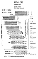
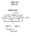
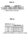
- Fig. 1 (A) shows an example of 7-bit binary numbers, in which A/0 represents A or O.
- each number A, B or N is divided into the unit number of bits (digits) (e.g. 32 bits) before repeating the additions and subtractions, the number of the additions and subtractions further increases.
- the number of bits (digits) n increases, there exists a problem in that the divided intermediate results must be stored in a great number of registers, so that it has been difficult to execute the computation (calculation) at high speed.
- a method of decreasing the number of additions and subtractions related to divisional operations with reference to a remainder reference table has been proposed.
- the above-mentioned method of using a remainder reference table is to transform a multiplication result represented by several higher significant bits into a remainder represented by lower significant bits after a 2n-bit multiplication result has been obtained. For instance, in the case of 4-bit unit, remainders by divisors or moduli N of 0001 x 2", 0010 x 2", ....
- 1111 x 2" are previously listed in a remainder reference table, and the multiplication result can be obtained by adding a value obtained by removing 4 higher significant bits to the remainder represented by the 4 higher significant bits, in order to reduce the number of bits one by one, and the computational processing is completed when the n-bit multiplication result has been obtained.
- Baker has proposed a method of using specialized circuits by interposing modular subtracters between two multiply additions, so that the operation can be executed by only n-bit length specialized circuits, as disclosed by "Fast Computation of A *B Modulo N", by P.W. Baker, Electron Letter, Vol. 23, No. 15, pp 794-795 (1987).
- n-bit partial products and n-bit partial modular subtracters are added or subtracted in sequence beginning from the most significant bits.
- the partial products are determined by taking bit by bit the multiplier B from the most significant bit and by adding A or 0 to the partial remainder.
- -2N, -N, 0, N. or 2N modular subtracters are determined according to the value of the partial remainder and then added to the partial remainder. The partial remainder is shifted one bit toward the most significant bit side, and the above operations are repeated.
- This Baker method can solve the problem involved in the specialized circuits; however, the computational speed is not improved because the number of additions and subtractions cannot be reduced markedly in comparison with the conventional method.
- the modular multiplication method of A x B modulo N where A denotes a multiplicand, B denotes a multiplier, N denotes a modulus, which comprises the steps of: (a) transforming A from A ⁇ [0, N] to A ⁇ [-N/2, N/2], where ⁇ denotes a set of integers; (b) setting the number of bits n of each variable of A, B or N; (c) initializing a remainder R; (d) determining the number of repeated processing stages k as k - ⁇ n/r ⁇ + 1 where r denotes a radix number r ⁇ 2' (r ⁇ 1); ⁇ n/r' ⁇ denotes a maximum integer less than n/r ; and - denotes a substitution; (e) updating a partial remainder R and forming a partial multiplier b and a partial quotient c both within a range of -r
- the step of transforming A comprises the steps of: (a) comparing an absolute multiplicand
- N/2; (b) if
- N/2, proceeding to the step (b) in claim 1; and (c) if
- the step of setting the number of bits n of each variable of A, B or N comprises the step of setting n as n - ⁇ log 2 N ⁇ + 1, where ⁇ log 2 N ⁇ denotes a maximum integer less than log 2 N.
- the partial multiplier b(k) can be formed on the basis of the multiplier B in accordance with the following expression as where b(k) lies within a range of -r/2 ⁇ b(k) ⁇ r/2, and r denotes a radix number, and ⁇ x ⁇ denotes a maximum integer less than x.
- the partial quotient c(k) is formed by defining following comparative indices l i (b(k-1)), l -i (b(k-1)) immediately after the multiplicand A has been transformed, as follows:
- a first modification of the step of updating the partial remainder R and forming the partial multiplier b and partial quotient c comprises the steps of: (a) forming a present stage partial multiplier b(k); (b) updating a succeeding stage partial remainder R(k-1) by the present stage partial remainder R(k) and the present stage partial multiplier b(k) as R(k-1) - rR(k) + b(k)A; (c) forming a succeeding stage partial multiplier b(k-1); (d) forming the present stage partial quotient c(k); (e) further updating the succeeding stage partial remainder R(k-1) by the succeeding stage remainder R(k-1) and the present stage partial modular subtracter c(k)N as R(k-1) -- R(k-1) - c(k)N; and (f) progressing the present stage (k) as k - k-1; (g) checking whether the present stage (k) is zero; (h) if the present stage (k
- a second modification of the step of updating the partial remainder R and forming the partial multiplier b and partial quotient c comprises the steps of: (a) initializing a preceding stage partial quotient c(k + 1) to zero as c(k + 1) - 0; (b) forming a present stage partial multiplier b(k); (c) updating a succeeding stage partial remainder R-(k-1) by a present stage partial remainder R(k), a preceding stage partial quotient c(k + 1) and a present stage partial multiplier b(k) as R(k-1) - r ⁇ R(k) - c(k + 1)N) + b(k)A; (d) forming a succeeding stage partial multiplier b(k-1); (e) forming a present stage partial quotient c(k); (f) progressing the present stage (k) as k - k-1; (g) checking whether the present stage (k) is zero; (h) if the present stage (k
- the step of transforming the final stage partial remainder R into a solution of A x B mod N comprises the steps of: (a) checking whether the final stage partial remainder R(0) is used as a multiplicand A for a succeeding modular multiplication computation; (b) if R(0) is used, substituting the remainder R(0) for A as A - R(0); (c) if R(0) is not used, checking whether R(0) ⁇ 0; (d) if R(0) ⁇ 0, ending the processing stage; and (e) if R(0) ⁇ 0, substituting R(0) and the modulus N for R(0) as R(O) - R(0) + N, before ending the processing stage.
- the modular multiplication Isystem comprises: (a) first means (41) for transforming a data A to A - N if
- the Baker method can reduce the quantity of data transferred between the computing elements and the memory unit. In this Baker method, however, since the radix number 2 for multiply additions is different from that 4 for division (modular) subtractions, it has been difficult to markedly decrease the computation stages or to increase the computational speed.
- the gist of the present invention is to reduce the number of multiply additions and division (modular) subtractions on the basis of the same higher radix number. For instance, when a radix number 4 is selected, since partial products and modular subtracters can be computed two bits by two bits as shown in Fig. 1 (C), it is possible to reduce the number of computational stages of additions/subtractions down to half of the conventional method. In general, when a radix number r is selected, the number of stages of additions and subtractions can be reduced down to I/Iog 2 r.
- both the methods adopt the similar processing such that the partial remainder is updated by adding a partial product (which constitutes a multiply-addition stage) and a modular subtracter (which constitutes a modular-subtraction stage) to the partial remainder obtained as an intermediate result during computation processing.
- the feature of the present invention is to adopt the same any given higher radix number for both the partial products and modular subtracters by the following methods:
- the above first feature serves to prevent bit overflow from a limited computational range and the second feature is a necessary condition to adopt the same radix number for both the partial products and the modular subtracters.
- the feature of the present invention is to expand partial products and modular subtracters on the basis of the same higher radix number and further to determine the modular subtracters in anticipation of a carry at the succeeding stage.
- no carry propagation adders are incorporated in the system during intermediate computation stages.
- the number of the prior-art additions and subtractions can be reduced by expanding computational operations on the basis of a higher radix r.
- additions and subtractions of a multiple of the modulus N are interposed between the two additions and/or subtractions for partial products to execute the modular multiplication in the same way as by Baker method shown in Fig. 1 (B).
- the two additions and/or subtractions can be executed simultaneously, being different from the Baker method by which the succeeding processing is determined by observing the sequentially executed current addition/subtraction results, it is possible to increase the speed twice.
- the system can be applied to a cryptographic system excellent in secrecy as well as in computational speed.
- the system can be simply extended to a larger scale by connecting additional cells in series.
- the modular multiplication is to compute A x B modulo (mod) N, where A denotes a multiplicand; B denotes a multiplier; and N denotes a modulus.
- the final remainder can be obtained by repeatedly executing the following formulae: where R new denotes the updated or succeeding partial remainder; R old denotes the current partial remainder; - denotes the substitution; r denotes the radix number; b denotes the partial multiplier obtained when the multiplier B is expanded on the basis of r-notation; c denotes the partial quotient determined by comparing boundary indices t (described later) obtained by A, N, b, and r with the partial remainder R on the basis of a modified Robertson diagram (described later).
- rR old + bA is represented by R'; the boundary indices l i is determined by the succeeding stage partial multiplier b; and the partial quotient c is determined by the t i .
- R' is represented by R'; l i is determined by the present partial multiplier b; and the partial quotient c has previously been determined.
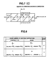
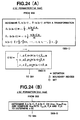
- Fig. 1 (C) is an example of computational bit arrangement diagram for assistance in explaining a computation of A x B mod N (39 x 93 mod 121) by the present invention in 7-bit binary numbers and a radix number of 4, in comparison with the conventional method and the Baker method shown in Figs. 1 (A) and 1 (B).
- the conventional method requires 7 multiply-additions of 7 partial products based on a radix number of 2 and 7 division-subtractions of 7 modular subtracters based on a radix number of 2;
- the Baker method requires 6 multiply-additions of 6 partial products based on a radix number of 2 and 7 division-subtractions of 7 modular subtracters based on a radix number of 4;
- the invention method requires only 3 multiply-additions/subtractions of 3 partial products based on a radix number of 4 and 4 division-additions/subtractions of 4 modular subtracters based on a radix number of 4.
- the feature of the invention method is to adopt the same higher radix number r for both the partial multipliers b and partial quotient within a range of -r/2 ⁇ b, c ⁇ r/2 in order to markedly reduce the number of computational stages (additions/subtractions), as described in further detail hereinbelow.
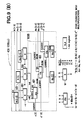
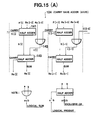
- FIGs. 2(A) and 2(B) show a conceptual block diagram for executing the computational method of the present invention.
- the modular multiplication system shown in Fig. 2(A) roughly comprises a register block 1, a control block 2 and an operating block 3.
- the register block 1 comprises an A register 11 for storing an input variable A (multiplicand), a B register 13 for storing an input variable B (multiplier), an N register 15 for storing an input variable N (modulus), and an R register 17 for storing work variables R (partial remainder) which is composed of an R sum register 17 s for storing a sum of R and an R carr y register for storing a carry of R.
- the control block 2 comprises an N normalizer 21 for normalizing the variable N, a control parameter generator 23 and a sequence controller 23 for controlling the entire sequential operations of the system.
- the control parameter generator 23 comprises a b generator 23A for generating partial multipliers b on the basis of B as described later in further detail with reference to Fig. 23(A) to (E); a c generator 23B for generating partial quotients (modulus) c on the basis of A, N, R, b and I (boundary indices) as described later in further detail with reference to Figs. 24(A) to (C); a boundary index generator 23C for generating boundary indices t on the basis of A, N, and b and supplying the generated boundary indices t to the c generator 23B as described later in further detail with reference to Figs.
- the operating block 3 comprises a bA generator 31 for generating partial products bA on the basis of A and b; a cN generator 33 for generating modular subtracters cN on the basis of N and c; and an updated R generator 35 for generating an updated remainder R(k-1) on the basis of the partial remainders R(k) where k denotes the number of processing stages from k to o; a carry save adder 37 for updating Raid to R new on the basis of bA, cN, and R, bit by bit, without carry propagation; and a carry propagation adder 39 for outputting a final remainder R(0) as a solution of A x B mod N.
- the updated A is stored in the A register 11 again so that A can be transformed from a range 0 ⁇ A ⁇ N to a range -N/2 A ⁇ N/2 in order to prevent the bits from overflowing from a predetermined computational range.
- the R register 17 for holding a partial remainders R is initialized by the sequence controller 25. Thereafter, the variables A, B and R stored in the A register 11, B register 13 and the R register 17 are supplied to the parameter generator 23 to generates b, c and R. Further, the bA generator 31, the cN generator 33 and the R generator 35 output bA, cN and R, respectively. These values are added by the carry save adder 37 bit by bit and the sum thereof is stored in the R register 17 as a new partial remainder R. The above steps are repeated n times corresponding to the number of bits of N.
- the bA generator 31, the cN generator 33 and the R generator 35 output 0, N or 0, and R, respectively.
- These values are added by the carry save adder 37 and then outputted from the carry propagation adder 39 by propagating a carry in sequence beginning from the least significant bit, through an output port.
- N is added according to the value of R, and R is transformed within a range 0 5 R ⁇ N for modular multiplication.
- Fig. 1 (C) when the radix number is r in the present invention, integer times additions or subtractions for modular subtractions are intercomputed between the additions or subtractions for partial products; the absolute values of the partial remainder R during computation are determined within a predetermined computational range in order to reduce the number of computational stages down to the number n of bits of N. Therefore, no data stand-by control is required; the speed can be increased; the circuit scale can be reduced; and the circuit design can be facilitated.
- the Baker method has been proposed by which additions for multiplication and subtractions for division are executed in sequence, as shown in Fig. 1 (B).
- the computational speed of the present invention is higher than that of Baker. This is because in the present invention, the multiplicand A is previously transformed and further the addition or subtraction for modular subtraction is previously adjusted on the basis of the value of a partial product at the succeeding stage before added to the partial product. Therefore, the Baker method is executed by multiply-additions based on radix 2 and modular-additions/subtractions based on radix 4, so that if the number of bits of a binary modulus N is n, n times operations are required.
- the multiplication and division can be executed by multiply- and modular-additions/subtractions based on the same radix 4, for instance, it is possible to reduce the, operation times to half or to increase the computational speed twice.
- the radix number is r ⁇ 2' (r ? 1), the number of operations can be reduced down to 1/r' times.
- Fig. 3 is a block diagram showing the entire configuration of the modular multiplication of the basic embodiment where the radix number is 4.
- This system comprises first means of an input distributer circuit 41 for receiving input variables A, B, N through a parallel arranged input port and for distributing these data bit by bit; second means of operating sections 43 composed of a plurality of series-connected cells 43a, 43b ...
- the controller 45 stores a multiplier B and forms a partial multiplier b, reads remainders R sum and R carr y stored in the cells arranged for higher significant bits in order to form a partial quotient c, and updates the values in the registers by new R sum an R carr y. after the entire processing has been completed. Further, when a carry is overflowed from an output bit length, the coverflow carry is stored and added to the lower significant bits of the succeeding input data by the adder including output shaping circuit 49.
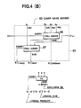
- Fig. 4(A) is a block diagram showing a first embodiment of each cell incorporated in the modular multiplier system according to the present invention, which corresponds to the cell 63i shown in Fig. 3 for executing the afore-mentioned formula (A).
- the cell shown in Fig. 4(A) comprises an N register 51 for holding N, an A register 53 for holding A, an R carr y register 55 for holding R carr y. a R sum register 57 for holding R sum , a bA generator 59 for forming a partial product bA, a cN generator 61 for forming a modular subtracter cN, and a 5-input carry save adder 63.
- the cN generator 61 provides the same function as with the bA generator 59, where i denotes an i-th bit from the least significant bit.
- the 5-input carry save adders 63 arranged from the cell number (n + 3) to (n-m + 1) are so constructed as to add 4R + bA on the basis of the intermediate results c i '; and R(i) midsum in order to form c.
- B[i] > 0; i > n or 0 ⁇ i; and B[i] 1; i > n if B has a minus sign.
- the additions are executed by the carry save adder except the final addition.
- R R + bA
- a new R sum is determined as and a new R carr y is determined as a new Rcarry: where e denotes the exclusive-OR operation; ⁇ denotes the logical product (AND operation); V denotes the logical sum (inclusive -OR operation).
- e denotes the exclusive-OR operation
- ⁇ denotes the logical product (AND operation)
- V denotes the logical sum (inclusive -OR operation).
- N to p, Atop and R top are usable instead of N, A and R.
- B[i] denotes an i-th bit from LSB.
- the N normalization step is added so that the modular multiplication can be executed by fixing the register bit length.
- the N normalization is executed by the N normalizer 21 of the control block 2 by sequentially shifting the N register 15 and the A register 11 leftward until the most significant bit of N becomes 1.
- step 6 indicates that the carry of the carry save addition result is propagated to obtain a final result and further the N normalization in step 2 is returned to the original N.
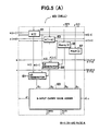
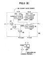
- Fig. 5A is a block diagram showing a second embodiment of each cell incorporated in the modular multiplication system according to the present invention, which corresponds to the cell 43i shown in Fig. 3 for executing the afore-mentioned formula (B).
- the cell shown in Fig. 5(A) comprises a 5-input carry save adder 69 as shown in Fig. 5(B) instead of the carry save adder 63 shown in Fig. 4(A).
- the 5-input carry save adder 63 in the cell shown in Fig. 5(A).
- the A register 53 is shifted by two bits, being different from that shown in Fig. 4(A), this is because 4-times bA is not required..
- the 5-input carry save adder 69 shown in Fig. 5(A) comprises two half adders 71 and 73, a full adder 75, two logical OR gates 77 and 79 and a logical AND gate 81.
- A R sum + 2R carry Shift N and A rightward by the same bits as in step 2 to obtain A.
- This second embodiment is equivalent to the first embodiment mathematically. In the first embodiment, however, since the sum (4R + A) in step 4 is used for both updated c and R according to the case, it takes much time to determine c. In this second embodiment, however, the simultaneous processing is enabled by repeatedly delaying the partial modular subtracter cN bit by bit. However, the number of additions in the final processing increases once.
- Step 1 (According to the cases)
- Step 2 (If R ⁇ 0)
- Step 3 (If R ⁇ 0)
- the value (R+bA/4)/N is controlled so as to lie within a predetermined range from -9/16 to 9/16.
- is classified according to two denominators 8 and 16 to simplify the boundary indices l for comparison. In this case, it is sufficient to compare 6 higher significant bits of N with l.
- Step 1 (According to the cases)
- Step 2 (If R ⁇ 0)
- Step 3 (If R ⁇ 0)
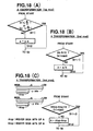
- Fig. 7(A) shows a modified Robertson diagram for assistance in explaining a method of deciding a partial quotient c by which the computation represented by the expression of R new ⁇ r x (R old - cN) + bA can be executed without bit overflow from a predetermined computational range.
- b o because only division is handled.
- lines having a gradient of 45 degrees represent integers c between -r/2 and r/2. These lines are determined within a window defined between -rd and rd in the axis of abscissa and between [-d-bA/rN and d-bA/rN] in the axis of ordinate.
- l denotes a boundary index which represents a middle point of a range where two adjacent sloped lines are overlapped.
- the comparative index t moves right and left, because the succeeding partial multiplier b changes and therefore the window moves up and down. However, since the partial multiplier b is defined to an integer between -r/2 and r/2, and further the comparative index within negative ranges of t.
- the previously obtained comparative indices can be restricted.
- the present R ⁇ /N value where R ⁇ /N ⁇ (r(R-cN) + bA)/N is calculated and then plotted on the axis of abscissa. That is, the partial quotient line c is determined by comparing R/N with the comparative index l.
- boundary variable d is determined (as explained later in Appendix (1)) as follows:
- Fig. 7(C) shows a modified Robertson diagram for assistance in explaining the basis of the first and second embodiments, which represents an intermediate state of the repeated computations.
- R(k) denotes the present remainder
- R(k-1) denotes the succeeding remainder.
- the abscissa represents a value of (4R(k) + b(k)A)/N which corresponds to an addition of partial products in Fig. 1(C), and the ordinate represents the succeeding remainder R(k-1)/N.
- a partial quotient c(-2 to 2) can be determined by the graphs.
- the graph can be expressed as
- the graphs lie between -9/4 and 9/4 on the abscissa and between -9/16 - b(k-1)A/4N and 9/16 - b(k-1)-A/4N on the ordinate.
- R + bA/4 lies always within a range from -9/16 to 9/16.
- the graph representation range(window) changes according to the value bA.
- N top is m bits, since the error is 21-m or less.
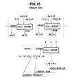
- Fig. 8 is a table for comparing the computational speed between the present invention and the Baker method in modular multiplication, in which the numbers of repeated additions and subtractions are compared by use of n-bit length operating circuits. For instance, when the average bits of B distribute as 1 or 0, and n denotes a bit length of a modulus N, Baker method requires n/2 multiply additions/subtractions and 3n/4 modular additions/subtractions and therefore 5n/4 additions/subtractions in total on an average, and similarly n multiply and modular additions/subtractions and therefore 2n additions/subtractions in total at the maximum.
- the method of the present invention requires 3n/8 multiply and modular additions/siubtractions and therefore 3n/4 additions/subtractions in total on an average and similarly n/2 multiply and modular additions/subtractions and therefore n multiply and modular additions/subtractions in total at the maximum.
- This indicates that the computational speed of the invention method is 1.7 times higher than the Baker method on an average and twice higher than the Baker method at the maximum.
- Fig. 9(A) is a block diagram showing a third embodiment of each cell 43i incorporated in the modular multiplication system according to the present invention shown in Fig. 4(A), in which the partial remainder R represented in redundant form can be directly substituted for a multiplier B at the succeeding processing stage.
- a carry save adder 63A applicable to a radix number of 4 is shown.
- (n + r') piece cells 43i must be connected in series into an array form to realize a r-radix modular multiplication system.
- the computation of the expression of R new ⁇ r x (R old - cN) + bA can be executed by the carry save adder 63A which can eliminate the carry propagation times.
- Fig. 9(B) is a block diagram showing a fourth embodiment of each cell 43i incorporated in the modular multiplication system according to the present invention shown in Fig. 4(A), in which the partial remainders R represented in redundant form can be directly substituted again for a multiplier B at the succeeding stage and further the multiplicand A is also represented in redundant form.
- the following fourth method can be executed.
- the computational result is used as the succeeding multiplicand. Therefore, when a high-speed modular exponentiation is required, it is preferable to determine the modular multiplication result of the redundant representation as the multiplicand of the succeeding modular multiplication without carry propagation.
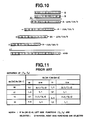
- Step 2 (Repetition of ⁇ n/r' ⁇ + 1 times)
- the comparative index l is a midpoint at a region where two lines are overlapped on the axis of abscissa in Fig. 7; l i ⁇ i - 1/2 - bA/rN, l -i ⁇ -i + 1/2 -bA/rN; b is an integer within a range between -r/2 and r/2; i is an integer within a range between 1 and r/2. Both the integers b and i are previously determined.
- the comparative indices can be determined simply.
- the function fc is compared in accordance with an approximate processing method.
- a and R have a sign
- Atop and R to p also have a sign ( ⁇ ).
- the comparison between the comparative index with the partial remainder R can be attained by comparing only several higher significant bits of ti and R.
- N is transformed in accordance with an approximate processing method.
- N to p and 2Atop are compared instead of comparison between N and 2A.
- N to p denotes y higher significant bits of N
- Atop denotes A lying beyond a range of N used for forming the N to p. Further, since A has a sign, Atop also has a sign.
- the maximum throughput of LSIs now on the market for RSA public-key cryptosystems is about 30 kbit/s.
- LSIs large- scale integrated circuits
- the present invention has been adopted to the systems, it is possible to increase the throughput approximately twice without increasing the hardware volume. Further, it is possible to more increase the throughput in principle with increasing hardware volume. In other words, it is possible to economically realize LSIs with a basic transfer speed of 64 kbit/s.
- the method and the system of the present invention enable high speed data processing by means of a relatively small-volume hardware. For instance, at present it takes several minutes for a single RSA cryptographic processing in the case of an IC card chip (provided with an 8-bit microprocessor). However, it is possible to reduce the same cryptographic processing time down to several seconds, when the method and system of the present invention are incorporated in the IC card chip. Further, the present invention is effectively applicable to various systems which require a high speed modular multiplication processing, without being limited to cryptographic and authentic systems which require multibit length modular multiplication or modular exponentiation computations.
- the modular multiplication method and the system according to the present invention can realize a high speed computation r' times higher than the prior-art method and system. Further, the system can be configured by simply arranging the same circuits in series for facilitation of system design.
- the modular subtracters for division must be checked whenever the partial remainders are added, since only the higher significant bits are checked, it is possible to reduce the number of comparison operations down to 1/r' times, thus reducing the number of comparator circuits and the capacity of the memory incorporated in the system. In addition, since the number of memory access is reduced, the computational speed can be increased.
Landscapes
- Physics & Mathematics (AREA)
- General Physics & Mathematics (AREA)
- Engineering & Computer Science (AREA)
- Computational Mathematics (AREA)
- Mathematical Analysis (AREA)
- Mathematical Optimization (AREA)
- Pure & Applied Mathematics (AREA)
- Theoretical Computer Science (AREA)
- Computing Systems (AREA)
- General Engineering & Computer Science (AREA)
- Mathematical Physics (AREA)
- Complex Calculations (AREA)
Applications Claiming Priority (6)
| Application Number | Priority Date | Filing Date | Title |
|---|---|---|---|
| JP17700/89 | 1989-01-30 | ||
| JP1017700A JPH02199532A (ja) | 1989-01-30 | 1989-01-30 | 剰余乗算の方法および回路 |
| JP147795/89 | 1989-06-09 | ||
| JP1147795A JP2812365B2 (ja) | 1989-06-09 | 1989-06-09 | 乗算回路 |
| JP206973/89 | 1989-08-11 | ||
| JP20697389A JP2790327B2 (ja) | 1989-08-11 | 1989-08-11 | 剰余乗算回路および剰余乗算方法 |
Publications (3)
| Publication Number | Publication Date |
|---|---|
| EP0381161A2 true EP0381161A2 (de) | 1990-08-08 |
| EP0381161A3 EP0381161A3 (de) | 1992-03-25 |
| EP0381161B1 EP0381161B1 (de) | 1998-12-09 |
Family
ID=27281933
Family Applications (1)
| Application Number | Title | Priority Date | Filing Date |
|---|---|---|---|
| EP90101842A Expired - Lifetime EP0381161B1 (de) | 1989-01-30 | 1990-01-30 | Verfahren und System zur modularen Multiplikation |
Country Status (4)
| Country | Link |
|---|---|
| US (1) | US5073870A (de) |
| EP (1) | EP0381161B1 (de) |
| CA (1) | CA2008774C (de) |
| DE (1) | DE69032811T2 (de) |
Cited By (3)
| Publication number | Priority date | Publication date | Assignee | Title |
|---|---|---|---|---|
| WO1993020503A1 (en) * | 1992-04-07 | 1993-10-14 | Thomson Consumer Electronics S.A. | Method and apparatus for modulo computation |
| CN1085862C (zh) * | 1996-09-20 | 2002-05-29 | 张胤微 | 高速模乘法装置 |
| SG115534A1 (en) * | 2003-04-04 | 2005-10-28 | St Microelectronics Asia | Method and apparatus for performing modular arithmetic |
Families Citing this family (30)
| Publication number | Priority date | Publication date | Assignee | Title |
|---|---|---|---|---|
| US5270956A (en) * | 1991-03-18 | 1993-12-14 | University Of Maryland | System and method for performing fast algebraic operations on a permutation network |
| US5274707A (en) * | 1991-12-06 | 1993-12-28 | Roger Schlafly | Modular exponentiation and reduction device and method |
| US5513133A (en) * | 1992-11-30 | 1996-04-30 | Fortress U&T Ltd. | Compact microelectronic device for performing modular multiplication and exponentiation over large numbers |
| US5349551A (en) * | 1993-07-30 | 1994-09-20 | The United States Of America As Represented By The Director Of National Security Agency | Device for and method of preforming an N-bit modular multiplication in approximately N/2 steps |
| FR2726667B1 (fr) * | 1994-11-08 | 1997-01-17 | Sgs Thomson Microelectronics | Procede de mise en oeuvre de multiplication modulaire selon la methode montgomery |
| US5793659A (en) * | 1996-10-15 | 1998-08-11 | United Microelectronics Corporation | Method of modular reduction and modular reduction circuit |
| KR100218683B1 (ko) * | 1996-12-04 | 1999-09-01 | 정선종 | 정보 보호용 모듈러 승산 장치 |
| US6748410B1 (en) | 1997-05-04 | 2004-06-08 | M-Systems Flash Disk Pioneers, Ltd. | Apparatus and method for modular multiplication and exponentiation based on montgomery multiplication |
| ES2293677T3 (es) * | 1997-05-04 | 2008-03-16 | Sandisk Il Ltd | Aparato y metodo mejorados para la multiplicacion y exponenciacion modulares basadas en la multiplicacion de montgomery. |
| US6144740A (en) * | 1998-05-20 | 2000-11-07 | Network Security Technology Co. | Method for designing public key cryptosystems against fault-based attacks with an implementation |
| US6925563B1 (en) | 1999-09-22 | 2005-08-02 | Raytheon Company | Multiplication of modular numbers |
| US7269261B1 (en) | 1999-09-22 | 2007-09-11 | Raytheon Company | Key escrow systems |
| DE60139401D1 (de) * | 2000-05-15 | 2009-09-10 | Sandisk Il Ltd | Erweiterung des bereichs rechnerischer körper von ganzen zahlen |
| US6954772B2 (en) * | 2000-08-28 | 2005-10-11 | Sun Microsystems, Inc | Method and apparatus for performing modular division |
| KR100436814B1 (ko) * | 2001-12-20 | 2004-06-23 | 한국전자통신연구원 | 아이씨카드용 알에스에이 암호 연산 장치 |
| DE10219158B4 (de) * | 2002-04-29 | 2004-12-09 | Infineon Technologies Ag | Vorrichtung und Verfahren zum Berechnen eines Ergebnisses einer modularen Multiplikation |
| US7558817B2 (en) | 2002-04-29 | 2009-07-07 | Infineon Technologies Ag | Apparatus and method for calculating a result of a modular multiplication |
| DE10223853B4 (de) * | 2002-05-28 | 2005-06-23 | Technische Universität Braunschweig Carolo-Wilhelmina | Verfahren und integrierte Schaltung zur Durchführung einer Multiplikation modulo M |
| KR100459732B1 (ko) * | 2002-12-30 | 2004-12-03 | 삼성전자주식회사 | 4-2 컴프레서를 이용한 몽고메리 모듈러 승산기 및 그승산 방법 |
| US20040252829A1 (en) * | 2003-04-25 | 2004-12-16 | Hee-Kwan Son | Montgomery modular multiplier and method thereof using carry save addition |
| FR2859030B1 (fr) * | 2003-08-21 | 2005-11-04 | Gemplus Card Int | Procede de realisation d'une multiplication modulaire et procede de realisation d'une multiplication euclidienne sur des nombres de 2n bits |
| JP4180024B2 (ja) * | 2004-07-09 | 2008-11-12 | Necエレクトロニクス株式会社 | 乗算剰余演算器及び情報処理装置 |
| JP4170267B2 (ja) * | 2004-07-09 | 2008-10-22 | Necエレクトロニクス株式会社 | 乗算剰余演算器及び情報処理装置 |
| DE102006025713B9 (de) * | 2005-10-28 | 2013-10-17 | Infineon Technologies Ag | Kryptographie-Vorrichtung und Kryptographie-Verfahren zum Berechnen eines Ergebnisses einer modularen Multiplikation |
| DE102006025673B9 (de) | 2005-10-28 | 2010-12-16 | Infineon Technologies Ag | Rechenwerk zum Reduzieren einer Eingabe-Zahl bezüglich eines Moduls |
| DE102006025569A1 (de) * | 2005-10-28 | 2007-05-03 | Infineon Technologies Ag | Vorrichtung und Verfahren zum Berechnen einer Multiplikations-Additions-Operation und zum Berechnen eines Ergebnisses einer modularen Multiplikation |
| DE102006025677B4 (de) * | 2005-10-28 | 2020-03-12 | Infineon Technologies Ag | Vorrichtung und Verfahren zum Berechnen eines Ergebnisses einer Summe mit einem Rechenwerk mit begrenzter Wortlänge |
| US8073892B2 (en) * | 2005-12-30 | 2011-12-06 | Intel Corporation | Cryptographic system, method and multiplier |
| DE102014222825A1 (de) * | 2014-11-07 | 2016-05-12 | Ihp Gmbh - Innovations For High Performance Microelectronics / Leibniz-Institut Für Innovative Mikroelektronik | Vorrichtung und Verfahren zur Multiplikation zur Erschwerung von Seitenkanalangriffen |
| RU2019121710A (ru) * | 2016-12-12 | 2021-01-12 | Конинклейке Филипс Н.В. | Электронное вычислительное устройство, выполненное с возможностью вычисления произведения целых чисел |
Family Cites Families (2)
| Publication number | Priority date | Publication date | Assignee | Title |
|---|---|---|---|---|
| JPS54144148A (en) * | 1978-05-01 | 1979-11-10 | Aisuke Katayama | Exponential conversion type high speed multiplying system |
| JPS6042965B2 (ja) * | 1979-06-01 | 1985-09-26 | 愛介 片山 | 複数法形高速乗算装置 |
-
1990
- 1990-01-29 CA CA002008774A patent/CA2008774C/en not_active Expired - Fee Related
- 1990-01-29 US US07/471,787 patent/US5073870A/en not_active Expired - Lifetime
- 1990-01-30 DE DE69032811T patent/DE69032811T2/de not_active Expired - Fee Related
- 1990-01-30 EP EP90101842A patent/EP0381161B1/de not_active Expired - Lifetime
Non-Patent Citations (4)
| Title |
|---|
| * the whole document * * |
| IBM TECHNICAL DISCLOSURE BULLETIN. vol. 20, no. 4, September 1977, NEW YORK US pages 1483 - 1484; NUSSBAUMER: 'MULTIPLIER CIRCUIT IN TRANSFORMED DOMAIN' * |
| IEEE TRANSACTIONS ON COMPUTERS. vol. C-34, no. 9, September 1985, NEW YORK US pages 789 - 796; TAKAGI ET AL: 'High-Speed VLSI Multiplication Algorithm with a Redundant Binary Addition Tree' * |
| Lecture Notes in Computer Science, 263; Advances in Cryptology-CRYPTO '86, Proceedings; pp 277-301; Orton et al: ' VLSI implementation of public-key encryption algorithms' * |
Cited By (3)
| Publication number | Priority date | Publication date | Assignee | Title |
|---|---|---|---|---|
| WO1993020503A1 (en) * | 1992-04-07 | 1993-10-14 | Thomson Consumer Electronics S.A. | Method and apparatus for modulo computation |
| CN1085862C (zh) * | 1996-09-20 | 2002-05-29 | 张胤微 | 高速模乘法装置 |
| SG115534A1 (en) * | 2003-04-04 | 2005-10-28 | St Microelectronics Asia | Method and apparatus for performing modular arithmetic |
Also Published As
| Publication number | Publication date |
|---|---|
| EP0381161B1 (de) | 1998-12-09 |
| DE69032811T2 (de) | 1999-04-29 |
| CA2008774A1 (en) | 1990-07-30 |
| US5073870A (en) | 1991-12-17 |
| EP0381161A3 (de) | 1992-03-25 |
| DE69032811D1 (de) | 1999-01-21 |
| CA2008774C (en) | 1999-10-05 |
Similar Documents
| Publication | Publication Date | Title |
|---|---|---|
| EP0381161A2 (de) | Verfahren und System zur modularen Multiplikation | |
| US5144574A (en) | Modular multiplication method and the system for processing data | |
| EP0421092B1 (de) | Verfahren und Gerät zur Ausführung mathematischer Funktionen mit Hilfe polynomialer Annäherung und eines Multiplizierers rechteckigen Seitenverhältnisses | |
| KR100591761B1 (ko) | 몽고메리 모듈러 곱셈기 및 캐리 저장 가산을 이용한몽고메리 모듈러 곱셈 방법 | |
| EP0356153B1 (de) | Verfahren und Gerät zur Radix-2**n-Division mit überlappender Quotientenbitauswahl und gleichzeitiger Rundung und Korrektur des Quotienten | |
| KR20110105555A (ko) | 효율적인 하드웨어 구성을 갖는 몽고메리 승산기 | |
| US5132925A (en) | Radix-16 divider using overlapped quotient bit selection and concurrent quotient rounding and correction | |
| JPH0969040A (ja) | 推測的演算を有する3つのオーバーラップしたステージにより基数2の平方根演算/除算を行う回路 | |
| EP0502782A2 (de) | Mikroschaltung für die Implementation von RSA-Algorithmen und von gewöhnlicher und modulärer Arithmetik, insbesondere Exponentation, mit grossen Operanden | |
| EP0297588B1 (de) | Mit Pseudo-Division arbeitender arithmetischer Prozessor für trigonometrische Funktionen | |
| US6847986B2 (en) | Divider | |
| US7539720B2 (en) | Low latency integer divider and integration with floating point divider and method | |
| US4899302A (en) | Arithmetic unit for inverse trigonometric function | |
| JP2004519017A (ja) | 係数乗算するための方法および装置 | |
| US7921149B2 (en) | Division and square root arithmetic unit | |
| EP0436905B1 (de) | Hochleistungsaddierer mit Carry-Vorhersage | |
| US20090006509A1 (en) | High-radix multiplier-divider | |
| JPH1195982A (ja) | 演算処理回路及び演算処理方法並びに演算処理システム | |
| Cekli et al. | A high speed pipelined radix-16 Booth multiplier architecture for FPGA implementation | |
| Kuang et al. | A low-cost high-speed radix-4 Montgomery modular multiplier without carry-propagate format conversion | |
| US7266577B2 (en) | Modular multiplication apparatus, modular multiplication method, and modular exponentiation apparatus | |
| KR100329914B1 (ko) | 제산장치 | |
| US7607165B2 (en) | Method and apparatus for multiplication and/or modular reduction processing | |
| Lewis | Complex logarithmic number system arithmetic using high-radix redundant CORDIC algorithms | |
| EP0546977A2 (de) | Verfahren und Vorrichtung zur Lösung numerischer Probleme unter Verwendung mehreren parallel arbeitenden Datenverarbeitungsvorrichtungen |
Legal Events
| Date | Code | Title | Description |
|---|---|---|---|
| PUAI | Public reference made under article 153(3) epc to a published international application that has entered the european phase |
Free format text: ORIGINAL CODE: 0009012 |
|
| 17P | Request for examination filed |
Effective date: 19900130 |
|
| AK | Designated contracting states |
Kind code of ref document: A2 Designated state(s): DE FR GB NL |
|
| PUAL | Search report despatched |
Free format text: ORIGINAL CODE: 0009013 |
|
| AK | Designated contracting states |
Kind code of ref document: A3 Designated state(s): DE FR GB NL |
|
| 17Q | First examination report despatched |
Effective date: 19951107 |
|
| RAP1 | Party data changed (applicant data changed or rights of an application transferred) |
Owner name: NIPPON TELEGRAPH AND TELEPHONE CORPORATION |
|
| GRAG | Despatch of communication of intention to grant |
Free format text: ORIGINAL CODE: EPIDOS AGRA |
|
| GRAG | Despatch of communication of intention to grant |
Free format text: ORIGINAL CODE: EPIDOS AGRA |
|
| GRAH | Despatch of communication of intention to grant a patent |
Free format text: ORIGINAL CODE: EPIDOS IGRA |
|
| GRAH | Despatch of communication of intention to grant a patent |
Free format text: ORIGINAL CODE: EPIDOS IGRA |
|
| GRAA | (expected) grant |
Free format text: ORIGINAL CODE: 0009210 |
|
| AK | Designated contracting states |
Kind code of ref document: B1 Designated state(s): DE FR GB NL |
|
| REF | Corresponds to: |
Ref document number: 69032811 Country of ref document: DE Date of ref document: 19990121 |
|
| ET | Fr: translation filed | ||
| PLBE | No opposition filed within time limit |
Free format text: ORIGINAL CODE: 0009261 |
|
| STAA | Information on the status of an ep patent application or granted ep patent |
Free format text: STATUS: NO OPPOSITION FILED WITHIN TIME LIMIT |
|
| 26N | No opposition filed | ||
| REG | Reference to a national code |
Ref country code: GB Ref legal event code: IF02 |
|
| PGFP | Annual fee paid to national office [announced via postgrant information from national office to epo] |
Ref country code: GB Payment date: 20070109 Year of fee payment: 18 |
|
| PGFP | Annual fee paid to national office [announced via postgrant information from national office to epo] |
Ref country code: NL Payment date: 20070110 Year of fee payment: 18 |
|
| PGFP | Annual fee paid to national office [announced via postgrant information from national office to epo] |
Ref country code: DE Payment date: 20070227 Year of fee payment: 18 |
|
| PGFP | Annual fee paid to national office [announced via postgrant information from national office to epo] |
Ref country code: FR Payment date: 20070105 Year of fee payment: 18 |
|
| GBPC | Gb: european patent ceased through non-payment of renewal fee |
Effective date: 20080130 |
|
| NLV4 | Nl: lapsed or anulled due to non-payment of the annual fee |
Effective date: 20080801 |
|
| PG25 | Lapsed in a contracting state [announced via postgrant information from national office to epo] |
Ref country code: NL Free format text: LAPSE BECAUSE OF NON-PAYMENT OF DUE FEES Effective date: 20080801 Ref country code: DE Free format text: LAPSE BECAUSE OF NON-PAYMENT OF DUE FEES Effective date: 20080801 |
|
| REG | Reference to a national code |
Ref country code: FR Ref legal event code: ST Effective date: 20081029 |
|
| PG25 | Lapsed in a contracting state [announced via postgrant information from national office to epo] |
Ref country code: GB Free format text: LAPSE BECAUSE OF NON-PAYMENT OF DUE FEES Effective date: 20080130 |
|
| PG25 | Lapsed in a contracting state [announced via postgrant information from national office to epo] |
Ref country code: FR Free format text: LAPSE BECAUSE OF NON-PAYMENT OF DUE FEES Effective date: 20080131 |