EP0381401A2 - Bilderzeugungsgerät - Google Patents
Bilderzeugungsgerät Download PDFInfo
- Publication number
- EP0381401A2 EP0381401A2 EP90300873A EP90300873A EP0381401A2 EP 0381401 A2 EP0381401 A2 EP 0381401A2 EP 90300873 A EP90300873 A EP 90300873A EP 90300873 A EP90300873 A EP 90300873A EP 0381401 A2 EP0381401 A2 EP 0381401A2
- Authority
- EP
- European Patent Office
- Prior art keywords
- image forming
- image carrier
- lower body
- forming portion
- conveying path
- Prior art date
- Legal status (The legal status is an assumption and is not a legal conclusion. Google has not performed a legal analysis and makes no representation as to the accuracy of the status listed.)
- Granted
Links
Images


Classifications
-
- G—PHYSICS
- G03—PHOTOGRAPHY; CINEMATOGRAPHY; ANALOGOUS TECHNIQUES USING WAVES OTHER THAN OPTICAL WAVES; ELECTROGRAPHY; HOLOGRAPHY
- G03G—ELECTROGRAPHY; ELECTROPHOTOGRAPHY; MAGNETOGRAPHY
- G03G21/00—Arrangements not provided for by groups G03G13/00 - G03G19/00, e.g. cleaning, elimination of residual charge
- G03G21/16—Mechanical means for facilitating the maintenance of the apparatus, e.g. modular arrangements
- G03G21/18—Mechanical means for facilitating the maintenance of the apparatus, e.g. modular arrangements using a processing cartridge, whereby the process cartridge comprises at least two image processing means in a single unit
- G03G21/1839—Means for handling the process cartridge in the apparatus body
- G03G21/1842—Means for handling the process cartridge in the apparatus body for guiding and mounting the process cartridge, positioning, alignment, locks
- G03G21/1853—Means for handling the process cartridge in the apparatus body for guiding and mounting the process cartridge, positioning, alignment, locks the process cartridge being mounted perpendicular to the axis of the photosensitive member
-
- G—PHYSICS
- G03—PHOTOGRAPHY; CINEMATOGRAPHY; ANALOGOUS TECHNIQUES USING WAVES OTHER THAN OPTICAL WAVES; ELECTROGRAPHY; HOLOGRAPHY
- G03G—ELECTROGRAPHY; ELECTROPHOTOGRAPHY; MAGNETOGRAPHY
- G03G21/00—Arrangements not provided for by groups G03G13/00 - G03G19/00, e.g. cleaning, elimination of residual charge
- G03G21/16—Mechanical means for facilitating the maintenance of the apparatus, e.g. modular arrangements
- G03G21/1642—Mechanical means for facilitating the maintenance of the apparatus, e.g. modular arrangements for connecting the different parts of the apparatus
- G03G21/1647—Mechanical connection means
-
- G—PHYSICS
- G03—PHOTOGRAPHY; CINEMATOGRAPHY; ANALOGOUS TECHNIQUES USING WAVES OTHER THAN OPTICAL WAVES; ELECTROGRAPHY; HOLOGRAPHY
- G03G—ELECTROGRAPHY; ELECTROPHOTOGRAPHY; MAGNETOGRAPHY
- G03G21/00—Arrangements not provided for by groups G03G13/00 - G03G19/00, e.g. cleaning, elimination of residual charge
- G03G21/16—Mechanical means for facilitating the maintenance of the apparatus, e.g. modular arrangements
- G03G21/1661—Mechanical means for facilitating the maintenance of the apparatus, e.g. modular arrangements means for handling parts of the apparatus in the apparatus
-
- G—PHYSICS
- G03—PHOTOGRAPHY; CINEMATOGRAPHY; ANALOGOUS TECHNIQUES USING WAVES OTHER THAN OPTICAL WAVES; ELECTROGRAPHY; HOLOGRAPHY
- G03G—ELECTROGRAPHY; ELECTROPHOTOGRAPHY; MAGNETOGRAPHY
- G03G2221/00—Processes not provided for by group G03G2215/00, e.g. cleaning or residual charge elimination
- G03G2221/16—Mechanical means for facilitating the maintenance of the apparatus, e.g. modular arrangements and complete machine concepts
- G03G2221/1651—Mechanical means for facilitating the maintenance of the apparatus, e.g. modular arrangements and complete machine concepts for connecting the different parts
- G03G2221/1654—Locks and means for positioning or alignment
-
- G—PHYSICS
- G03—PHOTOGRAPHY; CINEMATOGRAPHY; ANALOGOUS TECHNIQUES USING WAVES OTHER THAN OPTICAL WAVES; ELECTROGRAPHY; HOLOGRAPHY
- G03G—ELECTROGRAPHY; ELECTROPHOTOGRAPHY; MAGNETOGRAPHY
- G03G2221/00—Processes not provided for by group G03G2215/00, e.g. cleaning or residual charge elimination
- G03G2221/16—Mechanical means for facilitating the maintenance of the apparatus, e.g. modular arrangements and complete machine concepts
- G03G2221/1651—Mechanical means for facilitating the maintenance of the apparatus, e.g. modular arrangements and complete machine concepts for connecting the different parts
- G03G2221/1657—Mechanical means for facilitating the maintenance of the apparatus, e.g. modular arrangements and complete machine concepts for connecting the different parts transmitting mechanical drive power
-
- G—PHYSICS
- G03—PHOTOGRAPHY; CINEMATOGRAPHY; ANALOGOUS TECHNIQUES USING WAVES OTHER THAN OPTICAL WAVES; ELECTROGRAPHY; HOLOGRAPHY
- G03G—ELECTROGRAPHY; ELECTROPHOTOGRAPHY; MAGNETOGRAPHY
- G03G2221/00—Processes not provided for by group G03G2215/00, e.g. cleaning or residual charge elimination
- G03G2221/16—Mechanical means for facilitating the maintenance of the apparatus, e.g. modular arrangements and complete machine concepts
- G03G2221/1651—Mechanical means for facilitating the maintenance of the apparatus, e.g. modular arrangements and complete machine concepts for connecting the different parts
- G03G2221/166—Electrical connectors
-
- G—PHYSICS
- G03—PHOTOGRAPHY; CINEMATOGRAPHY; ANALOGOUS TECHNIQUES USING WAVES OTHER THAN OPTICAL WAVES; ELECTROGRAPHY; HOLOGRAPHY
- G03G—ELECTROGRAPHY; ELECTROPHOTOGRAPHY; MAGNETOGRAPHY
- G03G2221/00—Processes not provided for by group G03G2215/00, e.g. cleaning or residual charge elimination
- G03G2221/16—Mechanical means for facilitating the maintenance of the apparatus, e.g. modular arrangements and complete machine concepts
- G03G2221/1678—Frame structures
-
- G—PHYSICS
- G03—PHOTOGRAPHY; CINEMATOGRAPHY; ANALOGOUS TECHNIQUES USING WAVES OTHER THAN OPTICAL WAVES; ELECTROGRAPHY; HOLOGRAPHY
- G03G—ELECTROGRAPHY; ELECTROPHOTOGRAPHY; MAGNETOGRAPHY
- G03G2221/00—Processes not provided for by group G03G2215/00, e.g. cleaning or residual charge elimination
- G03G2221/16—Mechanical means for facilitating the maintenance of the apparatus, e.g. modular arrangements and complete machine concepts
- G03G2221/18—Cartridge systems
- G03G2221/183—Process cartridge
- G03G2221/1853—Process cartridge having a submodular arrangement
- G03G2221/1869—Cartridge holders, e.g. intermediate frames for placing cartridge parts therein
Definitions
- the present invention relates to an image forming apparatus for forming an image on an image carrier in accordance with an electrophotographic method.
- an image carrier in an image forming apparatus is supported removably for the remedying of jam, for maintenance, or for replacement of the image carrier.
- an upper body is mounted to a lower body in which are mounted a paper conveying path and a transfer portion, and the image carrier is mounted to the upper body so as to be removable to this side along its axial direction.
- a support portion which removably supports an image carrier unit having an image carrier together with a developing unit is provided in a lower body having an upper opening and in which are contained a paper conveying path and a transfer portion, and the image carrier unit and the developing unit are pressed downwards elastically by a pressing member provided in an upper body.
- the number of parts disposed is large and the total weight thereof is also large, so the lower body is required to have high rigidity. Since the lower body is placed in a stable base or desk, it does not vibrate so much.
- the number of parts mounted in the upper body is small, the total weight thereof is small, and the upper body is reduced in weight so as to be opened and closed easily. Consequently, the upper body is apt to vibrate as compared with the lower body.
- a large working space is required for the mounting and removal of the image carrier because the carrier is pulled in its axial direction, and there is anxiety about its supported state over a long period because the image carrier is supported in a cantilevered state.
- a locking lever is provided on this side for preventing axial movements of the image carrier, it is impossible to prevent slight axial movements of the image carrier caused by variations in length of the image carrier or in association with the mounting position of the locking lever.
- an upper body is connected for opening and closing motion to the upper portion of a lower body in which are contained a paper conveying path and a transfer portion disposed in the paper conveying path; there is provided an image forming portion which comprises an image carrier unit having an image carrier and a developing unit; a support portion which is in abutment with the image forming portion is formed in the lower body; and a retaining means which engages the image forming portion is provided.
- the image forming portion comprising the image carrier unit and the developing unit is supported by the support portion in the lower body to which vibration is difficult to be transmitted and is fixed by the retaining means, so it is not necessary to provide an image forming portion pressing member in the upper body.
- Fig. 1 is a side view in vertical section showing the entire structure of an image forming apparatus embodying the invention.
- the reference numeral 1 denotes a lower body which constitutes a part of the body of the apparatus as an electrophotographic printer.
- the lower body 1 comprises a base cover 2 and an upper cover 3 which are bonded together.
- To the upper portion of the lower body 1 is mounted vertically pivotably one end of a top cover 4 which serves as an upper body.
- the upper cover 3 there is provided a paper conveying path 8 for the conveyance of each paper received in a paper feed cassette 7.
- a paper discharge path 10 for discharging the paper toward a paper catch tray 9 which is formed on the upper surface of the top cover 4.
- a changeover portion 11 for changing over the paper discharging route from one to the other between the paper discharge path 10 and a lateral direction of the lower body 1 which is on the extension of the paper conveying path 8.
- a paper feed roller 12 which comes into contact with the top paper in the paper feed cassette 7; a start sensor 13 for optically detecting the paper being conveyed; a resist roller 14 whose rotation is controlled by a detected signal from the start sensor 13; a transfer portion 15 for transferring a developed image on a later-described image carrier 24 onto the paper; a paper separating portion 16 for separating the paper from the image carrier 24; a high voltage power supply 17; and a fixing portion 18 for fixing the transferred image on the paper while holding the paper which has passed the transfer portion 15.
- the image forming portion 20 comprising an image carrier unit 21 and a developing unit 22.
- the image carrier unit 21 is constituted as follows. An image carrier 24 is mounted rotatably to both side faces of a support member 23. Then, a charger 25 for imposing an electric charge on the image carrier 24, a destaticizer 26 for uniforming the electric charge on the outer periphery of the image carrier 24, and a waste toner container 27, are attached to the support member 23.
- the developing unit 22 comprises a toner container 30, a developing roller 31 and a toner agitating blade 32, the developing roller 31 and the blade 32 being mounted to the toner container 30 (see Fig. 5).
- flange-like projections 31a adapted to contact the outer peripheral surface of both ends of the image carrier 24.
- an optical portion 33 for applying a beam of light to a photosensitive surface of the image carrier 24 is mounted to the inner surface of the top cover 4.
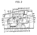
- Fig. 2 is a side view in vertical section, showing a support structure for the basket 19 and the image forming portion 20;
- Fig. 3 is an exploded perspective view showing the relation between the lower body 1 and the basket 19;
- Fig. 4 is a plan view of the basket 19 with the image forming portion 20 received therein.
- a pair of handles 34 positioned on both ends of the image carrier 24.
- the transfer portion 15 and the paper separating portion 16 are positioned by frames 39 which are fixed to the upper cover 3, and are held in place with bolts.
- the frames 39 are each formed with a support portion 40 for positioning and supporting each bearing 35 and a fulcrum portion 41 for positioning and pivotably holding each support shaft 37, and further formed with an upright, support portion 42 which is in abutment with the lower end of the waste toner container 27 of the image carrier unit 21.
- the support portion 40 and the fulcrum portion 41 are each in an upwardly divergent concave shape having an upper opening.
- the frames 39 are provided with retaining means 43 for resilient engagement with the image carrier unit 21.
- the retaining means 43 each comprise a locking lever 45 adapted to turn about a pivot shaft 44 and a locking lever 47 adapted to turn about a pivot shaft 46.
- the upper portions of the locking levers 45 and 47 are urged in opposite directions by virtue of a spring 48.
- the upper portion of one locking lever 45 is formed with a downward slant face 49 which presses the bearing 35 to the support portion 40 and an upward slant face 50 which is bent from the upper end of the downward slant face 49 in the opposite direction, while the other locking lever 47 is formed with a downward slant face 52 which presses a pin-shaped retaining projection 51 formed integrally on the outer side face of the support member 23 of the image carrier unit 21, and an upward slant face 53 which is bent from the upper end of the downward slant face 52 in the opposite direction.
- handles 54 are formed integrally with the housing of the destaticizer 26 which is a constituent member of the image carrier unit 21, and handles 56 are formed integrally on both outer sides of the toner container 30.
- the handles 54 and 56 are close to the handles 34 of the basket 19 to the extent that when the handles 34 are gripped by hands, fingers of the same hands can be brought into engagement with the handles 54 and 56.
- the handles 54 and 56 are formed with upward pressing portions 55, 57 and downward finger engaging portions 55a, 57a.
- a proximity portion 61 which is opposed through a predetermined gap to the upper edge of the support member 23 of the image carrier unit 21, as shown in Fig. 2.
- the fulcrum portion 41 are each positioned on the image carrier 24 side with respect to the center of gravity of the developing unit 22 and above the developing roller 31. Further, a motor 58 for driving both the developing roller 31 and the agitation blade 32 is fixed to the developing unit 22, and power input terminals 59 connected to the motor 58 project downwards from the developing unit. And a knife-shaped connector 60 which resiliently grips the power input terminals 59 is fixed to the inner surface of the frame 39 and is connected to a power source. The motor 58 is positioned in a direction leaving away from the image carrier 24 with respect to the fulcrum portions 41. As shown in Fig. 5, moreover, an opposed portion 62 which is opposed to a part of the toner container 30 through a predetermined gap s is formed on the inner surface of the top cover 4.
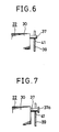
- Fig. 6 is a partial front view showing a state in which a support shaft 37 of the developing unit 22 is fitted in a fulcrum portion 41 of one frame 39, with the frame shown in section.
- the top cover 4 is turned upwards to open the upper surface of the upper cover 3, and in this state the basket 19 is pulled up together with the image carrier unit 21 and the developing unit 22 while gripping the handles 34, whereby the paper conveying path 8 is exposed.
- the image carrier unit 21 and the developing unit 22 can be removed independently while the basket 19 is allowed to be located in the interior of the upper cover 3.
- the bearings 35 of the image carrier unit 21 are fitted in the guide slots 36 of the basket 19 which has been taken out of the upper cover 3 and at the same time the support shafts 37 of the developing unit 22 are fitted in the guide slots 38, then while gripping the handles 34 of the basket 19, the bearings 35 are fitted in the support portions 40 of the frames 39 and the basket 19 is accommodated in the upper cover 3 while the support shafts 37 are fitted in the sulcrum portions 41.
- the image carrier unit 21 and the developing unit 22 are accommodated in the basket 19 while the bearings 35 or the support shafts 37 are fitted in the guide slots 36 or 38 and the support portions 40 or the fulcrum portions 41.
- the bearings 35 whose movements in the directions other than the vertical direction are inhibited by the guide slots 36 are supported by the upward slant faces 50 and the retaining projections 51 are supported by the upward slant faces 53 of the locking lever 47, but the pressing portions 55 of the handles 54 can be pressed by idle fingers of the hands gripping the handles 34 of the basket 19.
- the locking levers 45 pivot in the counterclockwise direction against the force of the springs 48 by virtue of a component of force which is generated by the abutment of the bearings 35 with the upward slant faces 50, thereby permitting a downward movement of the bearings 35.
- the retaining projections 51 are supported by the upward slant faces 53 of the locking levers 47, and by virtue of a component of force which is generated by the abutment of the retaining projections 51 with the upward slant faces 53 upon depression of the pressing portions 55 of the handles 54, the locking levers 47 pivot in the clockwise direction against the force of the springs 48, thus permitting a downward movement of the retaining projections 51.
- the locking levers 45 which have returned to the original positions by the restoring force of the springs 48 press the bearings 35 against the bottoms of the support portions 40 through the downward slant faces 49 thereof.
- the downward slant faces 52 of the locking levers 47 press the retaining projections 51 downwards, so that the lower edges of both side portions of the support member 23 are brought into pressure contact with the support portions 42.
- the support shafts 37 are positioned in the fulcrum portions 41 to support the developing unit 22. Since the fulcrum portions 41 are positioned above the developing roller 31 and on the image carrier 24 side with respect to the center of gravity of the developing unit 22, the developing unit 22 pivot in the clockwise direction about the fulcrum portions 41, so that the projections 31a formed at both ends of the developing roller 31 come into abutment with the outer periphery of the end portions of the image carrier 24, whereby the gap between the intermediate portion of the image carrier 24 and that of the developing roller 31 is maintained constant and in this stable state the developing unit 22 is mounted to the frames 39.
- the image carrier unit 21 and the developing unit 22 are mounted in a stable state to the frames 39 which serve to position and fix the transfer portion 15 and the paper separating portion 16, the position of the image carrier 24 relative to the transfer portion 15 and the paper separating portion 16 can be determined accurately.
- the bearings 35 press the downward slant faces 49 of the locking levers 45, and by virtue of a component of force generated by the abutment of the two the locking levers 45 turn in the counterclockwise direction against the force of the springs 48, thereby permitting an upward movement of the bearings 35.
- the retaining projections 51 press the downward slant faces 52 of the locking levers 47, and by virtue of a component of force generated by the abutment of the two the locking levers 47 turn in the clockwise direction against the force of the springs 48, thereby permitting an upward movement of the retaining projection 51.
- the opposed portion 62 of the top cover 4 it is possible to prevent the developing unit 22 from being floated by strong vibrations during transport for example. In this case, by forming the opposed portion 62 using a shock absorbing material, even interference thereof with the developing unit 22 would cause no damage. Moreover, since the opposed portion 62 is opposed to the developing unit 22 through the predetermined gap s , the vibration which is created by the application of an external force to the top cover 4 can be prevented from being transmitted to the developing unit 22.
- the proximity portion 61 presses the support member 23 upon closing of the top cover 4 even when the mounted state of the support member 23 is incomplete.
- the support member 23 when the support member 23 is fixed in its predetermined position, there is formed a slight gap between the proximity portion 61 and the support member 23, so there is no fear of vibration being transmitted from the top cover 4 to the support member 23. Since the number of components mounted through the frames 39 is large and heavy components are also required to be supported, the lower body 1 has high rigidity and is placed on a stable base or desk, so it scarcely vibrates. Thus, there is no fear of harmful vibrations being transmitted from the lower body 1 to the developing unit 22 and the image carrier unit 21.
- the developing unit 22 can be positioned with a high accuracy.
- the support shafts 37 are formed by molding integrally with the toner container 30 using a resin.
- synthetic resin chips for contact with the support shafts 37 may be stuck to the frames 39 in suitable positions, or the frames 39 themselves may be formed using a synthetic resin to prevent the abrasion of the support shafts 37.
- a projecting portion 37a may be formed at an end of each support shaft 37.
- the projecting portion 37a comes into contact with the side face of each frame 39 to serve as a guide member when the support shaft 37 is fitted in the fulcrum portion 41 and it also serves to prevent vibrations in the transverse direction of the developing unit 22. Moreover, even when the frame 39 is deformed and expanded in its width, the width can be corrected by fitting the support shaft 37 in the fulcrum portion 41.
Landscapes
- Physics & Mathematics (AREA)
- General Physics & Mathematics (AREA)
- Engineering & Computer Science (AREA)
- Computer Vision & Pattern Recognition (AREA)
- Electrophotography Configuration And Component (AREA)
- Dry Development In Electrophotography (AREA)
Applications Claiming Priority (6)
| Application Number | Priority Date | Filing Date | Title |
|---|---|---|---|
| JP1020351A JP2549430B2 (ja) | 1989-01-30 | 1989-01-30 | 画像形成装置 |
| JP20350/89 | 1989-01-30 | ||
| JP1020350A JPH02199470A (ja) | 1989-01-30 | 1989-01-30 | 画像形成装置 |
| JP20349/89 | 1989-01-30 | ||
| JP20351/89 | 1989-01-30 | ||
| JP1020349A JPH02199469A (ja) | 1989-01-30 | 1989-01-30 | 画像形成装置 |
Publications (3)
| Publication Number | Publication Date |
|---|---|
| EP0381401A2 true EP0381401A2 (de) | 1990-08-08 |
| EP0381401A3 EP0381401A3 (de) | 1992-03-18 |
| EP0381401B1 EP0381401B1 (de) | 1995-06-14 |
Family
ID=27282997
Family Applications (1)
| Application Number | Title | Priority Date | Filing Date |
|---|---|---|---|
| EP90300873A Expired - Lifetime EP0381401B1 (de) | 1989-01-30 | 1990-01-29 | Bilderzeugungsgerät |
Country Status (5)
| Country | Link |
|---|---|
| US (1) | US5049940A (de) |
| EP (1) | EP0381401B1 (de) |
| KR (1) | KR930002247B1 (de) |
| AU (1) | AU623215B2 (de) |
| DE (1) | DE69019999T2 (de) |
Cited By (4)
| Publication number | Priority date | Publication date | Assignee | Title |
|---|---|---|---|---|
| EP0496400A3 (en) * | 1991-01-25 | 1993-10-20 | Canon Kk | Electrophotographic image forming apparatus with a process cartridge mounting feature |
| US6084622A (en) * | 1993-04-28 | 2000-07-04 | Canon Kabushiki Kaisha | Frame structure and an image forming apparatus using such a frame structure |
| EP1341061A1 (de) * | 2002-02-27 | 2003-09-03 | Canon Kabushiki Kaisha | Entwicklerbehälter für eine Arbeitseinheit und dessen Montageverfahren |
| EP3805865A1 (de) * | 2018-03-30 | 2021-04-14 | Brother Kogyo Kabushiki Kaisha | Entwicklerkartusche |
Families Citing this family (9)
| Publication number | Priority date | Publication date | Assignee | Title |
|---|---|---|---|---|
| US5204713A (en) * | 1990-08-24 | 1993-04-20 | Tokyo Electric Co., Ltd. | Electrophotographic apparatus |
| KR930011661B1 (ko) * | 1990-10-25 | 1993-12-16 | 현대전자산업 주식회사 | 급지카세트를 제거한 레이저 빔 프린터 |
| US5170209A (en) * | 1991-02-20 | 1992-12-08 | Colorocs Corporation | Process cartridge for an intermediate transfer electrophotographic print engine |
| EP0527422B1 (de) * | 1991-08-13 | 1996-01-31 | Kabushiki Kaisha TEC | Bilderzeugungsgerät |
| KR0122443B1 (ko) * | 1993-09-28 | 1997-11-17 | 김광호 | 일반용지 모사전송 장치 |
| JPH10143050A (ja) * | 1996-09-12 | 1998-05-29 | Canon Inc | プロセスカートリッジ、現像剤容器、残余現像剤容器、プロセスカートリッジの組立方法、プロセスカートリッジの現像剤再充填方法、プロセスカートリッジに用いられる支持枠体及び支持枠体の組立て方法 |
| US6678489B1 (en) * | 2002-07-15 | 2004-01-13 | Lexmark International, Inc. | Two part cartridges with force biasing by printer |
| US8874003B2 (en) * | 2012-05-17 | 2014-10-28 | Fuji Xerox Co., Ltd. | Supporting mechanism and image forming apparatus |
| JP7139655B2 (ja) | 2018-03-30 | 2022-09-21 | ブラザー工業株式会社 | ドラムユニット |
Family Cites Families (8)
| Publication number | Priority date | Publication date | Assignee | Title |
|---|---|---|---|---|
| JPS56122049A (en) * | 1980-02-29 | 1981-09-25 | Toshiba Corp | Electronic copier |
| JPS5825651A (ja) * | 1981-08-07 | 1983-02-15 | Canon Inc | 画像形成装置 |
| US4588280A (en) * | 1982-08-17 | 1986-05-13 | Canon Kabushiki Kaisha | Image forming apparatus and process unit detachably mountable thereto |
| US4563078A (en) * | 1984-08-31 | 1986-01-07 | Xerox Corporation | Electrostatographic apparatus frame with plural alternative mounting elements |
| US4681422A (en) * | 1984-11-01 | 1987-07-21 | Tokyo Electric Co., Ltd. | Paper supply device for an electrostatic photographic printer |
| US4757344A (en) * | 1985-07-16 | 1988-07-12 | Ricoh Company, Ltd. | Imaging apparatus with detachable cartridges |
| KR920001973B1 (ko) * | 1986-01-24 | 1992-03-07 | 도오꾜오 덴끼 가부시끼가이샤 | 정전 사진장치 |
| GB2197258B (en) * | 1986-09-05 | 1991-05-22 | Ricoh Kk | Electrostatic recording apparatus |
-
1990
- 1990-01-17 KR KR1019900000545A patent/KR930002247B1/ko not_active Expired - Fee Related
- 1990-01-25 US US07/470,308 patent/US5049940A/en not_active Expired - Fee Related
- 1990-01-26 AU AU48875/90A patent/AU623215B2/en not_active Ceased
- 1990-01-29 EP EP90300873A patent/EP0381401B1/de not_active Expired - Lifetime
- 1990-01-29 DE DE69019999T patent/DE69019999T2/de not_active Expired - Fee Related
Cited By (11)
| Publication number | Priority date | Publication date | Assignee | Title |
|---|---|---|---|---|
| EP0496400A3 (en) * | 1991-01-25 | 1993-10-20 | Canon Kk | Electrophotographic image forming apparatus with a process cartridge mounting feature |
| US5528342A (en) * | 1991-01-25 | 1996-06-18 | Canon Kabuskiki Kaisha | Electrophotographic image forming apparatus with a process cartridge mounting feature |
| US5543891A (en) * | 1991-01-25 | 1996-08-06 | Canon Kabushiki Kaisha | Electrophotographic image forming apparatus with a process cartridge mounting feature |
| US6084622A (en) * | 1993-04-28 | 2000-07-04 | Canon Kabushiki Kaisha | Frame structure and an image forming apparatus using such a frame structure |
| EP1341061A1 (de) * | 2002-02-27 | 2003-09-03 | Canon Kabushiki Kaisha | Entwicklerbehälter für eine Arbeitseinheit und dessen Montageverfahren |
| US6684040B2 (en) | 2002-02-27 | 2004-01-27 | Canon Kabushiki Kaisha | Developing device, process cartridge, electrophotographic image forming apparatus, and developer container and method of assembling the developer container |
| EP3805865A1 (de) * | 2018-03-30 | 2021-04-14 | Brother Kogyo Kabushiki Kaisha | Entwicklerkartusche |
| US11249418B2 (en) | 2018-03-30 | 2022-02-15 | Brother Kogyo Kabushiki Kaisha | Developer cartridge |
| US11693331B2 (en) | 2018-03-30 | 2023-07-04 | Brother Kogyo Kabushiki Kaisha | Developer cartridge |
| US12174557B2 (en) | 2018-03-30 | 2024-12-24 | Brother Kogyo Kabushiki Kaisha | Developer cartridge |
| US12572090B2 (en) | 2018-03-30 | 2026-03-10 | Brother Kogyo Kabushiki Kaisha | Developer cartridge |
Also Published As
| Publication number | Publication date |
|---|---|
| KR930002247B1 (ko) | 1993-03-27 |
| DE69019999T2 (de) | 1996-02-15 |
| EP0381401B1 (de) | 1995-06-14 |
| EP0381401A3 (de) | 1992-03-18 |
| US5049940A (en) | 1991-09-17 |
| DE69019999D1 (de) | 1995-07-20 |
| AU4887590A (en) | 1990-08-16 |
| KR900012138A (ko) | 1990-08-03 |
| AU623215B2 (en) | 1992-05-07 |
Similar Documents
| Publication | Publication Date | Title |
|---|---|---|
| US5049940A (en) | Image forming apparatus | |
| JPH0138609Y2 (de) | ||
| JP2898332B2 (ja) | 電子写真装置 | |
| JP2584043B2 (ja) | 現像装置 | |
| JP2584044B2 (ja) | 現像装置 | |
| JPH02213859A (ja) | 画像形成装置 | |
| JP2953921B2 (ja) | 電子写真記録装置 | |
| JP2518914B2 (ja) | 画像形成装置 | |
| JPH02199469A (ja) | 画像形成装置 | |
| JP2749144B2 (ja) | 画像形成装置 | |
| JP2991265B2 (ja) | 電子写真装置 | |
| JPH02199471A (ja) | 画像形成装置 | |
| JPH02201482A (ja) | 像担持体保護装置 | |
| JPH07101328B2 (ja) | 画像形成装置 | |
| JP2518915B2 (ja) | 画像形成装置 | |
| JPH02199487A (ja) | 現像装置 | |
| JPH02199468A (ja) | 画像形成装置 | |
| JPH02199488A (ja) | 現像装置 | |
| JPH02199470A (ja) | 画像形成装置 | |
| JP2685953B2 (ja) | 像担持体ユニット保持装置 | |
| JPH0645971Y2 (ja) | 電子写真装置 | |
| JPH02282765A (ja) | 電子写真装置 | |
| JPH02213880A (ja) | 電子写真装置 | |
| JPH0116100Y2 (de) | ||
| JP2918351B2 (ja) | 画像形成装置 |
Legal Events
| Date | Code | Title | Description |
|---|---|---|---|
| PUAI | Public reference made under article 153(3) epc to a published international application that has entered the european phase |
Free format text: ORIGINAL CODE: 0009012 |
|
| 17P | Request for examination filed |
Effective date: 19900227 |
|
| AK | Designated contracting states |
Kind code of ref document: A2 Designated state(s): DE FR GB IT NL SE |
|
| PUAL | Search report despatched |
Free format text: ORIGINAL CODE: 0009013 |
|
| AK | Designated contracting states |
Kind code of ref document: A3 Designated state(s): DE FR GB IT NL SE |
|
| 17Q | First examination report despatched |
Effective date: 19930406 |
|
| GRAA | (expected) grant |
Free format text: ORIGINAL CODE: 0009210 |
|
| AK | Designated contracting states |
Kind code of ref document: B1 Designated state(s): DE FR GB IT NL SE |
|
| PG25 | Lapsed in a contracting state [announced via postgrant information from national office to epo] |
Ref country code: IT Free format text: LAPSE BECAUSE OF FAILURE TO SUBMIT A TRANSLATION OF THE DESCRIPTION OR TO PAY THE FEE WITHIN THE PRE;WARNING: LAPSES OF ITALIAN PATENTS WITH EFFECTIVE DATE BEFORE 2007 MAY HAVE OCCURRED AT ANY TIME BEFORE 2007. THE CORRECT EFFECTIVE DATE MAY BE DIFFERENT FROM THE ONE RECORDED.SCRIBED TIME-LIMIT Effective date: 19950614 Ref country code: NL Free format text: LAPSE BECAUSE OF FAILURE TO SUBMIT A TRANSLATION OF THE DESCRIPTION OR TO PAY THE FEE WITHIN THE PRESCRIBED TIME-LIMIT Effective date: 19950614 |
|
| REF | Corresponds to: |
Ref document number: 69019999 Country of ref document: DE Date of ref document: 19950720 |
|
| ET | Fr: translation filed | ||
| PG25 | Lapsed in a contracting state [announced via postgrant information from national office to epo] |
Ref country code: SE Effective date: 19950914 |
|
| NLV1 | Nl: lapsed or annulled due to failure to fulfill the requirements of art. 29p and 29m of the patents act | ||
| RAP2 | Party data changed (patent owner data changed or rights of a patent transferred) |
Owner name: KABUSHIKI KAISHA TEC |
|
| PG25 | Lapsed in a contracting state [announced via postgrant information from national office to epo] |
Ref country code: GB Effective date: 19960129 |
|
| PLBE | No opposition filed within time limit |
Free format text: ORIGINAL CODE: 0009261 |
|
| STAA | Information on the status of an ep patent application or granted ep patent |
Free format text: STATUS: NO OPPOSITION FILED WITHIN TIME LIMIT |
|
| 26N | No opposition filed | ||
| GBPC | Gb: european patent ceased through non-payment of renewal fee |
Effective date: 19960129 |
|
| PGFP | Annual fee paid to national office [announced via postgrant information from national office to epo] |
Ref country code: DE Payment date: 20010122 Year of fee payment: 12 |
|
| PGFP | Annual fee paid to national office [announced via postgrant information from national office to epo] |
Ref country code: FR Payment date: 20010125 Year of fee payment: 12 |
|
| PG25 | Lapsed in a contracting state [announced via postgrant information from national office to epo] |
Ref country code: DE Free format text: LAPSE BECAUSE OF NON-PAYMENT OF DUE FEES Effective date: 20020801 |
|
| PG25 | Lapsed in a contracting state [announced via postgrant information from national office to epo] |
Ref country code: FR Free format text: LAPSE BECAUSE OF NON-PAYMENT OF DUE FEES Effective date: 20020930 |
|
| REG | Reference to a national code |
Ref country code: FR Ref legal event code: ST |