EP0381406A2 - Dispositif et procédé pour mesurer la densité de flux magnétique - Google Patents
Dispositif et procédé pour mesurer la densité de flux magnétique Download PDFInfo
- Publication number
- EP0381406A2 EP0381406A2 EP90300882A EP90300882A EP0381406A2 EP 0381406 A2 EP0381406 A2 EP 0381406A2 EP 90300882 A EP90300882 A EP 90300882A EP 90300882 A EP90300882 A EP 90300882A EP 0381406 A2 EP0381406 A2 EP 0381406A2
- Authority
- EP
- European Patent Office
- Prior art keywords
- probe
- magnetic field
- cores
- flux density
- difference signal
- Prior art date
- Legal status (The legal status is an assumption and is not a legal conclusion. Google has not performed a legal analysis and makes no representation as to the accuracy of the status listed.)
- Withdrawn
Links
Images
Classifications
-
- G—PHYSICS
- G01—MEASURING; TESTING
- G01R—MEASURING ELECTRIC VARIABLES; MEASURING MAGNETIC VARIABLES
- G01R33/00—Arrangements or instruments for measuring magnetic variables
- G01R33/02—Measuring direction or magnitude of magnetic fields or magnetic flux
- G01R33/028—Electrodynamic magnetometers
Definitions
- This invention relates to apparatus for and a method of measuring the magnetic flux density associated with ferromagnetic material excited by a static or time-varying magnetic field.
- Magnetic Particle Inspection is commonly carried out on components made from ferromagnetic material.
- the procedure calls for the component to be magnetised, whereupon a magnetic ink is sprayed over the region of interest. Any cracks present in the component produce a strong leakage of the magnetic field which attracts the magnetic ink, thus allowing any defects in the component to be identified.
- the MPI technique is specified in the UK in British Standard BS6072, which calls for the value of the magnetic flux density present in the component under inspection to be 0.72 Tesla. In practise it has been found difficult to measure the magnetic flux density B in the component and many inspection procedures either make a very crude measurement of this value or rely on measuring the magnetic field H in air around the component. This practice means that BS6072 is often not strictly complied with. As a result, actual defects may not be detected, or conversely, spurious indications may be seen where no defects actually occur.
- An object of the present invention is to provide a means of producing a quantitative measurement of the magnetic flux density within a component. This enables MPI to be carried out as specified in BS6072. Also, since quantitative values of the magnetic flux density can be recorded, the inspection can be repeated, if necessary, under the same magnetic conditions.
- the invention also allows different methods of magnetisation to be compared, including alternating or static magnetising techniques.
- apparatus for measuring flux density within the surface of a ferromagnetic material excited by a magnetic field comprising a probe having one end for location on or adjacent the surface of the test material, first sensor means at said one end of the probe and capable of producing a first output signal representative of the strength of the magnetic field to which said first sensor means is subjected, second sensor means at the remote end of the probe and capable of producing a second output representative of the strength of the magnetic field to which said second sensor means is subjected, circuit means for producing a difference signal representing the difference between the first and second outputs, and means for displaying and/or recording said difference signal.
- the apparatus may be calibrated by testing a material of known flux density.
- a preferred construction of probe comprises two magnetically susceptible C-cores, preferably of ferromagnetic material, and a coil wound in one rotational sense on the crosspiece of one core and in the opposite rotational sense on the crosspiece of the other core.
- a single wire is employed to form the coils, being wound in a figure-of-eight starting at one core and finishing at the other.
- the required difference signal can be obtained directly between leads connected to the beginning and the end of the figure-of-eight coiled wire, the signal being suitably processed before display and/or recording. It will be understood that the output from the probe will, in this arrangement, be on induced voltage arising due to any imbalance between the magnetic flux (associated with the material under test) which passes through the C-cores.
- the C-cores may be made of laminated silicon iron and the figure-of-eight coil may comprise one hundred or so complete turns of thin wire.
- the end of the probe for contacting the test material i.e. the contact poles of the one C-core, may be shaped to fit the surface under inspection.
- the afore-described apparatus meets a particular requirement in magnetic particle inspection where components need to be magnetised to a known value of the internal flux density.
- Such a device needs to be capable of measuring the flux density derived from static magnetic fields such as those produced, for example, by permanent magnets or direct current (DC), and also time varying magnetic fields such as those resulting from alternating currents in cables or generated by winding AC carrying wire around a laminated yoke.
- the device should also be capable of measuring peak magnetic field levels from non-sinusoidal time varying fields such as those produced by thyristor chopped power supplies.
- a method of magnetic flux measurement using the afore-described differential probe wherein, in the case of a test material subject to a static magnetic field, the voltage output of the probe (difference signal) is integrated while the probe is moved from a position remote from the test material to a position on or adjacent the test material.
- a method of magnetic flux measurement using the afore-described differential probe wherein, in the case of a test material subject to a time-varying magnetic field, the voltage output of the probe is integrated over a given period while the probe is held on or adjacent the test material, and the integrated voltage signal is rectified before being passed to a peak detecting (AC) circuit and/or an averaging (DC) circuit.
- AC peak detecting
- DC averaging
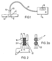
- a probe 10 is connected by a signal lead 12 to a housing 14 containing monitoring and processing electronics and having a display device 16.
- the probe 10 consists of two C-cores 18, 20 made typically of ferrite and a plurality, typically about one hundred, of turns of thin wire wound around the ferrite cores, in the manner shown in Figures 2 and 2A.
- the wire is wound around both cores, clockwise around one core and anti-clockwise around the other, in a figure-of-eight shape.
- a voltage signal is received from the coil whenever there is a change in the magnetic field linking the ferrite cores. However, if a magnetic field is applied equally to the two C-cores no difference voltage is produced, since the induced emf in one coil is cancelled out exactly by the induced emf in the other coil.
- a voltage signal from the probe will result only if the flux change through one core is different from the flux change through the other. This will occur, for example if the probe is positioned so that only one of the C-cores makes contact with the surface of a magnetised piece of steel.
- the C-core is made from material of high relative permeability (typically 500) and high saturation levels (typically 2 Tesla), so that it does not strongly influence the magnitude of any changes in magnetic flux passing through the core.
- the value of the magnetic flux through the C-cores is influenced by the flux density B within the component 24 under inspection. There is therefore no requirement to measure either the magnetic permeability of the material under inspection or the magnetic field H applied to the material.
- the monitoring electronics can give a reading of the flux density present in the surface under inspection.
- the electronics monitoring the induced voltages from the C-cores can operate in several modes.
- the field in the material to be inspected is static, such as that produced by direct current (DC) windings or by permanent magnets
- the voltage output from the probe is integrated whilst the probe is brought from a position remote from the inspection point up to the inspection point.
- the integrated voltage signal of the probe is indicative of the flux passage through one of the C-cores in the probe. This in turn is proportional to the flux density within the material under inspection.
- a magnetizable material such as that produced by alternating current in cables placed near a piece of steel or where electromagnets are powered by alternating current
- the probe is placed upon the material.
- the voltage produced by the probe will vary with the same periodicity as that of the driving field.
- a signal representing the magnetic flux density is obtained by integrating the voltage across the coil. This signal is rectified before being passed to peak detecting (AC) or averaging (DC) circuits, the result of which is displayed on a liquid crystal display. Conveniently, the display is latched for a period of typically 5 seconds after pressing a start button 26. The probe can then be removed from the test position and the recorded value for the flux density retained by the display.
- AC peak detecting
- DC averaging
- a calibration of the probe may be required using materials with a known applied time varying field.
- the probe acts as a shunt to the magnetic flux present in the surface of the test material and is useful where measurements of the surface flux are required.
- the probe If a surface is coated and therefore the probe cannot make intimate contact with the surface of the test material, then the probe provides a reading corresponding to the flux density at the external surface of the coating.
- the probe faces in contact with the surface under measurement may be shaped to make good contact, e.g. to fit curved surfaces of pipes.
- the devices may be used to show both the magnitude and direction of the magnetic flux density at the surface of ferromagnetic materials such as metals containing iron or nickel or cobalt and their alloys and also non-metals such as ferrites. This information measured by the apparatus is useful in providing quantitative information for use in non-destructive testing of materials and components, and especially for magnetic particle inspection.
- the probe can be used to detect whether or not magnetic flux is present inside a piece of material such as carbon steel, thereby to determine whether or not it can be successfully welded (if the flux density is too high then the welding arc is disrupted).
Landscapes
- Physics & Mathematics (AREA)
- Condensed Matter Physics & Semiconductors (AREA)
- General Physics & Mathematics (AREA)
- Investigating Or Analyzing Materials By The Use Of Magnetic Means (AREA)
- Measuring Magnetic Variables (AREA)
Applications Claiming Priority (2)
| Application Number | Priority Date | Filing Date | Title |
|---|---|---|---|
| GB8901903 | 1989-01-28 | ||
| GB8901903A GB2230341B (en) | 1989-01-28 | 1989-01-28 | Apparatus for and method of measuring magnetic flux density |
Publications (2)
| Publication Number | Publication Date |
|---|---|
| EP0381406A2 true EP0381406A2 (fr) | 1990-08-08 |
| EP0381406A3 EP0381406A3 (fr) | 1992-06-03 |
Family
ID=10650768
Family Applications (1)
| Application Number | Title | Priority Date | Filing Date |
|---|---|---|---|
| EP19900300882 Withdrawn EP0381406A3 (fr) | 1989-01-28 | 1990-01-29 | Dispositif et procédé pour mesurer la densité de flux magnétique |
Country Status (4)
| Country | Link |
|---|---|
| US (1) | US5122743A (fr) |
| EP (1) | EP0381406A3 (fr) |
| GB (1) | GB2230341B (fr) |
| IE (1) | IE63411B1 (fr) |
Cited By (1)
| Publication number | Priority date | Publication date | Assignee | Title |
|---|---|---|---|---|
| WO1994018575A1 (fr) * | 1993-02-03 | 1994-08-18 | Fraunhofer-Gesellschaft zur Förderung der angewandten Forschung e.V. | Detecteur horizontal utilisant des courants de foucault |
Families Citing this family (7)
| Publication number | Priority date | Publication date | Assignee | Title |
|---|---|---|---|---|
| GB2260413B (en) * | 1991-10-11 | 1996-04-24 | Mohammad Javad Birjandi | Search coil for detecting magnetic field components |
| US6316845B1 (en) | 1999-11-05 | 2001-11-13 | Parker Research Corporation | Battery powered AC electromagnetic yoke for magnetic particle inspection |
| US6707540B1 (en) | 1999-12-23 | 2004-03-16 | Kla-Tencor Corporation | In-situ metalization monitoring using eddy current and optical measurements |
| US6433541B1 (en) | 1999-12-23 | 2002-08-13 | Kla-Tencor Corporation | In-situ metalization monitoring using eddy current measurements during the process for removing the film |
| KR100696991B1 (ko) * | 2006-01-25 | 2007-03-20 | 한국원자력연구소 | 투자율 측정법을 이용하여 증기발생기 전열관의 와전류를탐상하는 장치 및 방법 |
| CN104569873A (zh) * | 2014-12-18 | 2015-04-29 | 郭月 | 一种液体抗磁性实验装置 |
| CN118191685B (zh) * | 2024-04-16 | 2024-11-15 | 广东开放大学(广东理工职业学院) | 一种基于恒定磁场对互感器极性判断的方法 |
Family Cites Families (14)
| Publication number | Priority date | Publication date | Assignee | Title |
|---|---|---|---|---|
| FR914545A (fr) * | 1945-09-17 | 1946-10-10 | Constr Telephoniques | Dispositif pour procéder au contrôle ou à la détermination de la perméabilité des tôles magnétiques |
| FR936032A (fr) * | 1946-11-06 | 1948-07-07 | Système de comparaison électro-magnétique de la perméabilité magnétique des corps et appareillage en permettant la réalisation | |
| US2957129A (en) * | 1956-03-30 | 1960-10-18 | Emmett M Irwin | Magnetic testing apparatus and method |
| FR1152505A (fr) * | 1956-06-26 | 1958-02-19 | Centre Nat Rech Scient | Perméamètre à variation de réluctance pour corps faiblement magnétiques |
| US3246219A (en) * | 1957-05-03 | 1966-04-12 | Devol | Ferroresonant devices |
| US3617874A (en) * | 1970-04-13 | 1971-11-02 | Foerster Friedrich M O | Magnetic leakage field flaw detector utilizing two ring core sensors |
| US3753096A (en) * | 1971-02-04 | 1973-08-14 | Automation Ind Inc | Eddy current flaw detection system with left off compensation |
| GB1385198A (en) * | 1971-07-16 | 1975-02-26 | British Iron Steel Research | Method and apparatus for testing ferromagnetic material |
| SE401901B (sv) * | 1976-05-20 | 1978-06-05 | Karlen Rune Ulrik | Anordning for induktiv avkenning av endringar i relativlege mellan ett objekt av magnetflodespaverkande material och en ferromagnetisk, fran objektet atskild horna |
| US4270088A (en) * | 1979-02-21 | 1981-05-26 | Otis Elevator Company | Method and apparatus for magnetically testing metal tapes |
| GB2078968B (en) * | 1980-06-24 | 1984-07-25 | Schonstedt Instrument Co | Magnetic sensors having misalignment compensating means |
| GB2083226B (en) * | 1980-08-23 | 1985-01-09 | Hocking Electronics Ltd | Eddy current testing probe |
| CA1244083A (fr) * | 1985-07-25 | 1988-11-01 | George Gee | Detecteur de corps ferromagnetiques |
| US4901015A (en) * | 1988-09-21 | 1990-02-13 | Sundstrand Corporation | Ambient electromagnetic field compensating magnetic pick-up circuit for integrated drive generators |
-
1989
- 1989-01-28 GB GB8901903A patent/GB2230341B/en not_active Expired - Lifetime
-
1990
- 1990-01-29 EP EP19900300882 patent/EP0381406A3/fr not_active Withdrawn
- 1990-01-29 US US07/471,796 patent/US5122743A/en not_active Expired - Fee Related
- 1990-01-29 IE IE31990A patent/IE63411B1/en not_active IP Right Cessation
Cited By (1)
| Publication number | Priority date | Publication date | Assignee | Title |
|---|---|---|---|---|
| WO1994018575A1 (fr) * | 1993-02-03 | 1994-08-18 | Fraunhofer-Gesellschaft zur Förderung der angewandten Forschung e.V. | Detecteur horizontal utilisant des courants de foucault |
Also Published As
| Publication number | Publication date |
|---|---|
| GB2230341B (en) | 1994-01-05 |
| US5122743A (en) | 1992-06-16 |
| IE63411B1 (en) | 1995-04-19 |
| GB2230341A (en) | 1990-10-17 |
| IE900319L (en) | 1990-07-28 |
| GB8901903D0 (en) | 1989-03-15 |
| EP0381406A3 (fr) | 1992-06-03 |
Similar Documents
| Publication | Publication Date | Title |
|---|---|---|
| US4528856A (en) | Eddy current stress-strain gauge | |
| US4059798A (en) | Method and apparatus for measuring the current flowing in a workpiece | |
| CN112444219B (zh) | 一种非接触超声电磁涂层测厚方法及其检测装置 | |
| US5565773A (en) | Arrangement of excitation and detection heads for detecting the magnetic properties of an object | |
| US5122743A (en) | Apparatus and method of non-destructively testing ferromagnetic materials including flux density measurement and ambient field cancellation | |
| JP2841153B2 (ja) | 微弱磁気測定方法及びその装置並びにそれを用いた非破壊検査方法 | |
| Wei et al. | A transducer made up of fluxgate sensors for testing wire rope defects | |
| JP2766929B2 (ja) | 非破壊検査装置 | |
| JPS6352345B2 (fr) | ||
| JPH11281678A (ja) | 電流センサ | |
| JPH0784021A (ja) | 微弱磁気測定装置及びそれを用いた非破壊検査方法 | |
| JPH0815229A (ja) | 高分解能渦電流探傷装置 | |
| JP3092837B2 (ja) | バルクハウゼンノイズ検出用磁気ヘッドおよびそれを用いた検出システム | |
| JP2005077203A (ja) | 透磁率測定方法及び測定装置 | |
| JPH09507294A (ja) | 金属製品を磁気的に試験する方法および装置 | |
| JP2812703B2 (ja) | 磁性薄膜の磁化特性測定装置 | |
| KR100267612B1 (ko) | 자성물질 상부의 비자성 물질 도금량 측정장치 | |
| CN215573468U (zh) | 一种测量矫顽力的u型探头 | |
| JP3223991U (ja) | 非破壊検査装置 | |
| JPH0812236B2 (ja) | 磁性薄膜の磁化特性測定装置 | |
| JPH07174730A (ja) | 磁気ヘッドおよびそれを用いた検出方法 | |
| SU789940A1 (ru) | Способ измерени коэрцитивной силы | |
| SU920591A1 (ru) | Способ измерени остаточных магнитных моментов ферромагнитных образцов разомкнутой формы /его варианты/ | |
| RU179750U1 (ru) | Устройство для локального контроля содержания ферромагнитных фаз в аустенитных сталях | |
| Weyand et al. | Fluxgate magnetometer for low-frequency magnetic electromagnetic compatibility measurements |
Legal Events
| Date | Code | Title | Description |
|---|---|---|---|
| PUAI | Public reference made under article 153(3) epc to a published international application that has entered the european phase |
Free format text: ORIGINAL CODE: 0009012 |
|
| AK | Designated contracting states |
Kind code of ref document: A2 Designated state(s): AT BE CH DE DK ES FR GB GR IT LI LU NL SE |
|
| PUAL | Search report despatched |
Free format text: ORIGINAL CODE: 0009013 |
|
| AK | Designated contracting states |
Kind code of ref document: A3 Designated state(s): AT BE CH DE DK ES FR GB GR IT LI LU NL SE |
|
| 17P | Request for examination filed |
Effective date: 19921201 |
|
| 17Q | First examination report despatched |
Effective date: 19940307 |
|
| STAA | Information on the status of an ep patent application or granted ep patent |
Free format text: STATUS: THE APPLICATION HAS BEEN WITHDRAWN |
|
| 18W | Application withdrawn |
Withdrawal date: 19961125 |