EP0381802A2 - Kabeltransmissionsverfahren und -gerät - Google Patents
Kabeltransmissionsverfahren und -gerät Download PDFInfo
- Publication number
- EP0381802A2 EP0381802A2 EP89104299A EP89104299A EP0381802A2 EP 0381802 A2 EP0381802 A2 EP 0381802A2 EP 89104299 A EP89104299 A EP 89104299A EP 89104299 A EP89104299 A EP 89104299A EP 0381802 A2 EP0381802 A2 EP 0381802A2
- Authority
- EP
- European Patent Office
- Prior art keywords
- data
- wireline
- pulse
- bit
- pulses
- Prior art date
- Legal status (The legal status is an assumption and is not a legal conclusion. Google has not performed a legal analysis and makes no representation as to the accuracy of the status listed.)
- Withdrawn
Links
- 230000005540 biological transmission Effects 0.000 title claims abstract description 68
- 238000000034 method Methods 0.000 title claims description 17
- 230000007704 transition Effects 0.000 claims abstract description 21
- 239000004020 conductor Substances 0.000 claims description 23
- 238000001514 detection method Methods 0.000 claims description 6
- 238000012163 sequencing technique Methods 0.000 claims description 4
- 230000004044 response Effects 0.000 claims description 2
- 230000002411 adverse Effects 0.000 abstract 2
- 230000008859 change Effects 0.000 description 15
- 238000010586 diagram Methods 0.000 description 6
- 238000013461 design Methods 0.000 description 5
- 238000005553 drilling Methods 0.000 description 5
- 230000001419 dependent effect Effects 0.000 description 4
- 230000010363 phase shift Effects 0.000 description 4
- 230000002238 attenuated effect Effects 0.000 description 2
- 239000013078 crystal Substances 0.000 description 2
- 239000012530 fluid Substances 0.000 description 2
- 238000012986 modification Methods 0.000 description 2
- 230000004048 modification Effects 0.000 description 2
- 230000036278 prepulse Effects 0.000 description 2
- 238000012545 processing Methods 0.000 description 2
- 238000011084 recovery Methods 0.000 description 2
- 230000009466 transformation Effects 0.000 description 2
- 230000009471 action Effects 0.000 description 1
- 230000001154 acute effect Effects 0.000 description 1
- 230000015572 biosynthetic process Effects 0.000 description 1
- 239000003990 capacitor Substances 0.000 description 1
- 238000010276 construction Methods 0.000 description 1
- 230000003111 delayed effect Effects 0.000 description 1
- 230000000694 effects Effects 0.000 description 1
- 230000007613 environmental effect Effects 0.000 description 1
- 238000005755 formation reaction Methods 0.000 description 1
- 230000001771 impaired effect Effects 0.000 description 1
- 238000005259 measurement Methods 0.000 description 1
- 230000008569 process Effects 0.000 description 1
- 230000001681 protective effect Effects 0.000 description 1
- 230000001172 regenerating effect Effects 0.000 description 1
- 230000000630 rising effect Effects 0.000 description 1
- 239000000126 substance Substances 0.000 description 1
Images


Classifications
-
- E—FIXED CONSTRUCTIONS
- E21—EARTH OR ROCK DRILLING; MINING
- E21B—EARTH OR ROCK DRILLING; OBTAINING OIL, GAS, WATER, SOLUBLE OR MELTABLE MATERIALS OR A SLURRY OF MINERALS FROM WELLS
- E21B47/00—Survey of boreholes or wells
- E21B47/12—Means for transmitting measuring-signals or control signals from the well to the surface, or from the surface to the well, e.g. for logging while drilling
-
- H—ELECTRICITY
- H04—ELECTRIC COMMUNICATION TECHNIQUE
- H04N—PICTORIAL COMMUNICATION, e.g. TELEVISION
- H04N5/00—Details of television systems
- H04N5/76—Television signal recording
- H04N5/91—Television signal processing therefor
- H04N5/92—Transformation of the television signal for recording, e.g. modulation, frequency changing; Inverse transformation for playback
- H04N5/9201—Transformation of the television signal for recording, e.g. modulation, frequency changing; Inverse transformation for playback involving the multiplexing of an additional signal and the video signal
Definitions
- This invention pertains to data communications and particularly to data communications on a wireline such as one employed in an oil or gas wellbore application.
- Such signals are typically used to remotely control the functions of various downhole devices such as sensors for detecting borehole parameters as well as tools and devices for performing functional operations in the borehole such as setting equipment or operating testers, motors, directional drilling equipment or the like, which may be operable in stages and in any event requiring a plurality of differing control signals at different times.
- a sheathed or armored cable which includes a single conductor as a core insulated from a protective conductive sheathing, which also acts as another electrical circuit path in conjunction with the core conductor to provide a conductive pair.
- Such so called single conductor wireline cables, or similarly constructed multi-conductor cables are almost exclusively used to operate downhole electrical devices because of a variety of reasons associated with the space limited and rigorous environment of a wellbore. In such oil and gas wellbore operations, a wellbore depth of many thousands of feet is not uncommon.
- control signals and data signals are normally converted to a digital code comprising a plurality of "0" and "1" bits that are transmitted at rates up to a maximum of 4 Kbits/second.
- a “1” is typically represented by a voltage sequence. That is, the "1" and “0” bits are represented by a sequencing of voltage levels.
- a “1” bit could be represented by a single first voltage level (e.g., a relatively high level) and a "0" bit could be represented by a single second level (e.g., a relatively low level).
- a "0" digit is commonly represented by a predetermined lower level voltage which may or may not be zero volts.
- a "1" is represented by a higher predetermined voltage level.
- Each bit has a predetermined time interval associated with it.
- Two or more successive bits of the same kind, either "0” or “1”, is represented by no change of voltage. There is only a voltage change when there is a change from a "0" to a “1” or a "1” to a "0".
- modulation schemes such as bi-phase voltage sequences and delayed modulation sequences, which are more complex than NRZ.
- the problems imposed by the wireline as discussed herein affect them all.
- a coded digital word would appear as a variable period, two-level rectangular wave voltage varying between a first voltage level and a second voltage level.
- the control and data information is carried by the changing voltage levels and by the number of bit time periods between the occurrences of the voltage changes.
- a conventional receiver or detector detects the first and second levels and the times of occurrence so as to be able to decode the transmission.
- the transmission and receiver scheme just discussed operates well when the rate of transmission does not exceed about 4 Kbits/second or the wireline is relatively short.
- the wireline transmission medium does cause a problem when the transmission is over a relatively long length or as the data rate increases. That is, the detection and distinguishing of the two voltage levels is impaired by distortions caused by the medium. Distortions become more acute for faster bit rates, where the periods at each of the two voltage levels are very short.
- the frequency characteristic of a typical single conductor wireline used for downhole application has about a 3 db loss at 5.6 Khz for a 30,000 foot length. At higher frequencies, the loss is significantly greater. When the loss reaches this 3 db level, it is referred to as a "cut-off" or "roll-off" frequency.
- Cut off is measured by increasing the frequency of a signal over a medium until the signal falls off or is attenuated to one half its transmitted amplitude due to losses in the medium.
- a 9.6 KBaud data rate is being used.
- good data transmission design practice would require a transmission medium having a cut-off frequency of at least 1-1/2 times the data rate being used. This would dictate a transmission medium having a 14.4 Khz cut-off frequency whereas the best low loss wireline in common usage in oil field work has a 5.6 Khz cut off, such wirelines being designed primarily for their mechanical capabilities as opposed to high frequency transmission characteristics, to accommodate the physically hostile borehole environment.
- Distortion consists primarily of amplitude losses and phase error. It is possible to overcome amplitude losses by making the voltage level between the two bit types be greater than for shorter line transmission. For example, a typical voltage level for a "0" bit could be 0 volts and a typical voltage level for a "1" bit could be 30 volts, a 30-volt difference. This difference could be doubled or made even greater so as to increase transmission efficiency for a longer transmission distance. However, there are practical limits as to what the voltage differences can be, particularly in the presence of a higher rate of transmission, such as 16 Kbits/second.
- phase error in this case describes the time distortion of a pulse by the transmitting medium so as to change the relative position of the pulses in a data stream from that of the original data stream.
- Significant phase error can make the time position of a pulse ambiguous and result in a data error.
- the amount of phase distortion incurred is proportional to the characteristics of the medium, transmission rate, modulation scheme and the particular data being sent at a particular time.
- Phase error is the principal limitation to high speed data transmission over wireline, limiting normal operation to less than approximately 4,000 bits per second.
- Oil field cable whether single or multi conductor, has characteristics which shift the leading and trailing edges of a signal in the time domain to generate phase error. If the occurrence of a leading or trailing edge is shifted forward or backward greater than one-half a bit time, it introduces an ambiguity into the data recovery process and there will be some bits that cannot be uniquely determined as to whether they are a one or a zero. This can be resolved to a certain degree by using error correcting codes or by establishing certain conditions into the data that the receiving circuitry can examine to decode ambiguities, but any such scheme complicates the data recovery process and can significantly increase the overall complexity of the receiver.
- the present invention involves the use of a wireline transmission system, which includes a transmitter, a receiver and usually a long wireline cable connected therebetween.
- Data is generated either at the surface location, e.g., as a command signal, or at the downhole location, resulting from measurement of a downhole parameter, for transmission to the other location.
- the data signal may be in the form of one of a variety of digital coding schemes, such as NRZ, utilizing a bi-level data bit state, which can be presented to the transmitter in conventional form where a "0" bit is represented by a first predetermined voltage level and a "1" bit is represented by a second predetermined voltage level. Each bit has a predetermined time interval or bit period.
- the coding scheme is NRZ and a high voltage level is used to represent a "1"
- a high voltage level is used to represent a "1”
- a processor at the transmission end of the system includes means for recognizing the start-up sequence and for generating a short duration pulse corresponding to the leading edge of the sequence or to any transitions in the start up sequence. This provides synchronization for the following data bits in the frame.
- the transmitter recognizes the ensuing data bits and generates a short duration pulse corresponding to each transition edge between a "1" data bit and a "0" data bit and visa versa. These short duration pulses are then applied to the wireline cable and thereby transmitted to the receiver.
- the processor at the surface sees the data in a time shifted relation to the data transmitted, in proportion to the wireline length and the delay characteristics of the particular cable. This delay causes no particular recognition or decoding difficulty.
- the frequency or pulse width of the short duration pulse is chosen so as to occupy a relatively small portion of the front end of a bit period.
- the receiver detects these short duration pulses on the wireline at a remote location and, through discrimination circuits, filters any noise from the received data signal stream.
- the filtered narrow pulses are then passed to a processor which detects the first start of frame narrow pulse and generates the predetermined voltage level for the start-up sequence until another short duration pulse is detected; at which time the appropriate corresponding voltage is generated.
- the output toggles back to the original voltage. This procedure of toggling on transitions is continued throughout the data stream, at which time the processor is returned to a condition preparatory to recognizing the next start-up sequence.
- the data stream is reconstituted into its original two-level data format.
- a wellbore operation is shown schematically, including a derrick, drilling platform 3 or the like, for providing a work platform to facilitate borehole operations.
- a wireline cable spool 4 is shown having a wireline 16 emanating therefrom and extending into a wellbore 6 which has been drilled into earth formations 7.
- Wellbore tool 31, 33 are shown suspended in the wellbore, which tools may be located therein for the purpose of performing wellbore operation or for detecting wellbore parameters.
- control signals passing from the surface to downhole locations are not distorted to the extent that misinterpretation of the data occurs.
- a combination of these conditions may exist.
- the accurate transmission of digitally encoded data between downhole and the surface of a well at a data rate above one and a half times the cut off frequency of a typical wireline conductor path is desirable.
- the transmission of such borehole data signals is accomplished during a borehole drilling operation, wherein the downhole tools 31, 33 are suspended within a relatively small diameter drill pipe.
- the tools or detectors 31, 33 may be suspended within a cased or open hole (as shown in Fig. 1) to perform operations or detect parameters when drill pipe is not present.
- a wireline transmission system wherein the transmission medium is a cable normally comprised of a single conductor or sometimes multiple conductors encased in an armored sheath for providing a rugged transmission medium that will withstand the rigorous mechanical and chemical environment typically constituting the borehole.
- All of the systems thus far described have advantages and disadvantages relative to the various environmental circumstances and physical limitations encountered in borehole operations.
- one of the most prevalent problems with all of the systems is that of data rate and, in particular, a high quality data signal at a reasonable data rate.
- One application for which the present invention is being utilized is to measure the orientation of a borehole bit being operated by a turbine.
- a useful data rate in such a system needs to be on the order of 10 KBaud.
- this baud rate would require a transmission medium having a roll off of 15 KHz.
- line (a) shows the digital code in the form of "1"'s and "0"'s which it is desired to transmit to a remote location.
- Line (b) of Fig. 2 shows the digital code converted into an NRZ format for transmission as a two voltage bi-level scheme to represent the digital code in a typical wireline transmission.
- Line (c) of Fig. 1 shows the average dc level of the signal as it would be received at a remote location after the signal has been subjected to line losses and phase shifting, which are characteristic of the prior art method of transmitting such signals.
- Line (d) of Fig. 1 shows the reconstituted NRZ data signal resulting from distortions in the data transmission over a wireline.
- a series of "1"'s and "0"'s which is digital code representative of data to be transmitted, is applied in sequence to a transmission line in the form of voltage levels.
- an initial start up sequence A is comprised of a positive voltage level applied to the line for a predetermined period, in this instance for one bit period, to represent a synchronization signal.
- the data sequence occurs at B, wherein the first data bit corresponding to the "0" in line (a) is at a zero voltage level.
- the next two data bits in period B represent a "1", as shown in line (a), wherein the voltage level increases to an increased voltage level, of say, 50 volts, and so on in this fashion until the data frame is completed, wherein no data is then transmitted for a period of time until and after the next ensuing start up sequence A is transmitted.
- all data streams contain a dc or average component associated with them, which is data dependent, as shown in line (c) of Fig. 2.
- a "1" is transmitted as a positive voltage, as used in the instant format, the voltage level rises to an on state for a bit period. If the data state changes to a "0", the dc component of the data stream on the line begins to decay. This corresponds to the portion of line (c) of Fig. 2 associated with part A of line B.
- Another portion of the data sequence is "up” (representing sequential "1"'s) for two bit periods and the dc component raises to a level that does not decay as rapidly as before, and thus the voltage level has now risen.
- the voltage level on the line represents an average level, which is directly related to the rate of change of the transition between voltage levels, i.e., it depends upon the amount of time at the previous level, as well as the amount of time at the new level.
- This average component of the data pushes and pulls the average signal level on the wireline up and down, as shown in line (c), and phase distortion results.
- the data bit, as reconstructed in NRZ format on line (d) at point P can be misinterpreted, in that the voltage level being detected by the receiver may be interpreted to be at a level representing a "1" rather than the "0", which was transmitted at the transmitting end of the system. It is noted that at point P of line (c) that the time intervals of the transitions are difficult to discern, and the two-step voltage format no longer appears in the discrete voltage level form shown in line (b). Phase error, as well as line losses, has produced an average voltage component characteristic of rounded corners and ill defined upward and lower voltage level conditions.
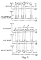
- Fig. 3 of the drawings the same data stream of "1"'s and “0"'s, and corresponding NRZ format bi-level waveform, as shown on line (b) of both Figs. 2 and 3, are utilized as a starting point for describing the functional features of the invention described herein.
- Fig. 3 also shows the initial start-up sequence, as indicated at A on line (a), followed by the first data bit indicated at B, etc., until the nine data bits comprising the data word are composed. Together they constitute a data burst or data sequence.
- Each bit of the word or sequence is of the same time interval, which is predetermined for a particular data transmission rate.
- each "1" data bit of the data word is at the same relatively high fixed voltage as the initial "1" start-up sequence, and each "0" data bit of the data word is at the same relatively low or zero fixed voltage.
- These voltages can be any value, including zero, but typical values used are, say, on the order of +150 volts for "1"'s and 0 volts for "0"'s.
- "1"'s are characterized by a drop of voltage to a low level, such as zero volts, and "0"'s are characterized by a higher level, say, 150 volts.
- polarity and amplitude may follow a variety of formats which may be desirable for some other functional reasons.
- the width (frequency) of the short duration pulse will be determined in the system of the present invention primarily by the baud rate.
- the baud rate determines the bit period, the width of which is the inverse of the baud rate. Therefore if we wanted to have a baud rate of 10,000 bits per second, we would have a bit width of 100 microseconds. If we were to use the full bit period to present a "1" or "0" bit state, as typically used in prior art NRZ transmissions, we would generate, at some time in the data stream, a substantial average dc voltage on the wireline, as shown at Fig. 2 line (c), which will tend to generate a phase shift problem on the wireline.
- a narrow pulse is used during some fractional portion of the bit period to represent the transition between bit states, as shown at line (d) of Fig. 2.
- a preferred format would be to generate the narrow pulse at the beginning of the bit period to occupy no more than 25% of the bit period on the transmission end of the system.
- these pulses may be made to be negative-going, and in fact such negative-going pulses may require less power, in that in the apparatus for generating the bi-level state, it would only be necessary to ground the positive charged wireline circuit.
- negative-going short duration pulses might be more desirable than that described above with respect to Figs. 2 and 3. If it were desired, however, to run the wireline in a negatively-charged state for some portion of the time, then the narrow pulse would be made to be positive-going. This could occur if you had two tool systems at the bottom of the wellbore and you reversed the polarity of the system in order to run one of the tool systems as opposed to the other.
- line (d) of Fig. 3 shows the waveform as it might appear at the receiving end of the wireline transmission system.
- the high-frequency short duration pulses which were impressed on the wireline (line (c), Fig. 3) are greatly attenuated by losses and phase distortion, as discussed above.
- Phase distortion is not bothersome as to the short duration pulses, since the voltage level is low, and therefore the average value of the signal voltage received changes very little, and thus the voltage decays to its pre pulse state well within the bit period.
- FIG. 3 shows the difference between the prior art method of using an NRZ format to transmit the data signal over the wireline, as compared to the short duration pulses of the present invention. It is significant to note that the individual pulse waveforms shown in line (d) of Fig. 3 would be greatly time shifted with respect to the transmitted pulses of line (c), over a long wireline, but such received pulses are only slightly phase shifted with respect to each other.
- Threshold detectors to be described herein with respect to Fig. 5 are used in the system to detect the occurrence of the short duration pulses as occurring at a voltage level between the threshold levels. Therefore, if noise exists on the line, an additional method of detecting such noise is provided by determining whether the signal in question occurred within the voltage range defined by the thresholds 10 and 11. If the peaks of voltage on the line were to be above the threshold 10, but below threshold 11, the signal would be received and reconstructed as a data signal. If noise were present on the line which did not provide a signal level above the threshold 10, no data signal would be received and reconstructed in accordance therewith. If the voltage peak is above threshold 11, likewise, no data signal is seen.
- the circuitry at the receiving end of the system for regenerating a data signal must determine if a pulse appearing on the wireline from the downhole or otherwise remote location, meets the time and amplitude threshold criteria of the system in order to detect and thereby eliminate noise signals from the system. If such a signal, at the received end of the system, passes the time and amplitude threshold criteria, a pulse is placed on the data received output line, as shown at line (e).
- this overall transmission system may shift the data with respect to time, i.e., the real time frame at which it was transmitted at the remote location, all of the data is shifted equally so that when the data pulse of line 3(e) is used to reconstruct the digital data line 3(f) in the original NRZ format, such shifting causes no data loss.
- the regenerated pulse resulting from detecting a data pulse is shown at line (e) and can be at a considerably lower voltage value than the pulses transmitted by the transmitter at the transmitting location, since they are only being generated at the received location for subsequent local processing.
- these regenerated pulses such as shown in line (e) of Fig. 3, can each have a wider pulse width than the narrow transmitted pulses, but such regenerated pulses should still be at a fraction of the period for an entire data bit.
- the regenerated pulses of line (e) Fig. 3 are used to reconstruct the two-level data format shown at line (f) in Fig. 4, i.e., the NRZ format in which the signal was transmitted, as shown in the top waveform (b) of Fig. 3.
- a block diagram shows surface electronics 12 at the top of the wellbore and downhole electronics 14 at the downhole tool location connected by a wireline 16.
- the scheme described herein may be used for transmitting data from downhole to the surface or from the surface to downhole, or in both directions.
- the wireline may be a single or multiple wire conductor 17 which has a grounded sheath or cable 18, as shown diagrammatically connected to the negative side of the circuit path.
- Surface power supply 20 provides the nominal operating voltages for system operation and in the system described produces, as for example, a positive dc output at 150 volts or more. It should be noted, however, that this system will perform even if the surface power supply is not used or present.
- a second power supply 22 serves as a surface transmitter power supply and produces a constant level positive 30-volt output which is connected by way of electronic switch 24 to add its voltage to that of a power supply 20.
- switch 24 when the switch 24 is open, only 150 volts are applied to wireline 16.
- switch 24 When switch 24 is closed, however, 180 volts are applied to the wireline.
- Surface control 26 turns on main power supply 20 and surface transmitter 28, which, in turn, operates the opening and closing of switch 24.
- Surface control 26 is arranged for either manual or automatic keying.
- An arrangement that may be used utilizes a waveform to be transmitted downhole for controlling the tool operation, which waveform may, for example, be comprised of conventional frequency shift coded bits.
- the amplitude of the coded frequency signal is, in this example, 30 volts when switch 24 is closed.
- This system disclosed for transmitting control signals downhole recognizes that at a low data transmission rate used for downhole tool control, the roll off loss of the wireline is sufficiently small to utilize a coded control signal to operate the downhole electronics without undergoing the data bit transformation of the present invention.
- Such data bit transformation is then utilized for uphole transmission, as described below. This would be because the surface to downhole transmission frequency is below the wireline cut off, i.e., less than 5.6 KHz.
- the downhole system 14 includes a downhole transformer 30 for detecting a change of current on the line. If a coded control signal is being transmitted from the surface, the current change is frequency modulated with one frequency representing a positive ("1") data pulse and the other frequency representing "0" low voltage level. As described earlier, this polarity can be reversed. When the current level changes on the wireline, the transformer 30 will see such a change, representing frequency shifts to "1" or "0". If the data pulse were originating at the surface, it would likely be a control data pulse being transmitted to the downhole tool.
- Downhole detector 30 utilizes these detected frequency shifts from the transformer to produce control instructions in the form of information frequency shifts which may then be reconstructed into a two-level NRZ format, or the like, for operating downhole equipment.
- the frequency shifts enter a phase-locked loop, whose phase detector produces the "1” “or “0” for the high or low frequency received.
- These "1" and “0" NRZ bits are sent to a Universal Asynchronous Receiver-Transmitter 32 for synchronization.
- These control bits determine the operation of a downhole tool control or processor 34, which is shown outputting to sensing transducers 31, 33 used for detecting downhole condition parameters.
- a pressure transducer 33 could be enabled by a signal from receiver 32 to processor 34 to sense the downhole pressure of the wellbore and, accordingly, to produce a digitally encoded output representative thereof to downhole transmitter 36.
- a second transducer 31 could be time shared to produce a similar signal as a measure of wellbore position, orientation or the like.
- the control signals can be used to alter the operating mode or computation constants in the downhole processor 34.
- Downhole power supply 38 produces the miscellaneous small voltages for the electronics located downhole and the 150-volt output typically used for the production of high frequency, short duration pulses.
- the power supply 38 is a converter which utilizes the wireline voltage to produce the 250 volts or the like utilized by the various downhole components of the system.
- An internal capacitor 40 is maintained charged and isolated by diode 44 for producing the small voltages required for operating the electronics when the 150-volt output line is shorted to ground during the data pulse production, as described below.
- a constant supply of low voltage is provided to the downhole components.
- This pulse may typically be in the range of one to ten microseconds. It is to be noted that the grounding of the wireline system, as just described, will produce a negative pulse rather than the positive pulse shown in Fig. 3, but that otherwise the concept is the same. It is not important to this invention whether the short pulses are negative-going or positive-going, but it is more typical of a system using a positive voltage main surface power supply for primary power, to use negative pulses and vice versa. Use of the negative pulses with the positive voltage power supply tends to save power and also provides a simple circuit design, in that it only requires grounding the line to provide the short duration pulses. The opening of the switch 42 again allows the wireline to return to 150 volts.
- Another Universal Asynchronous Receiver-Transmitter 32 utilizes a crystal controlled system clock to provide precise timing for the format of pulses transmitted to the surface. This format includes the start bit and the stop bit arranged around the data bits passed by the processor 34.
- the pulses of the type shown in line (d) of Fig. 3 are detected by a transformer detector 48, which is connected as the input to surface receiver 50.
- transformer 48 sees a change in current on the line 17 and provides an output voltage in response thereto to control the generation of a reconstructed data signal.
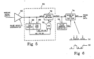
- the surface receiver 50 is shown in greater detail in Fig. 5. The surface receiver receives its input from the transformer 48 into a pulse height discriminator 62 which passes pulses that exceed a threshold voltage amplitude.
- This pulse height discriminator can also be arranged to pass voltages meeting upper and lower threshold limits, as by the use of an analog voltage comparator, which provides the high and low threshold detection function described with respect to levels 10 and 11 of line (d) of Fig. 3.
- the discriminator 62 thus passes a voltage on the line that has a certain threshold value or range of value to a pulse width or pulse duration discriminator 64.
- the pulse width discriminator is comprised of a one shot 66 which looks at the pulse duration, and if the pulse lasts for at least some period, say 10 microseconds, then discriminator 66 passes a control signal to AND GATE 70 which is comprised of an exclusive OR and a NAND GATE.
- a one shot 68 also receives the output of discriminator 62, and it also looks at the pulse duration.
- the pulse duration coming from discriminator 62 is not too wide, say its duration is not longer than 51 microseconds, then it also passes a control signal to AND GATE 70. If AND GATE 70 is satisfied by the outputs of discriminators 66 and 68, to be thereby activated, it allows the gating network 72 to pass the input signal from pulse height detector 62. The signal from gating network 72 is then fed to a divide by two flip flop 74, and also to a pulse absence detector 76. The output from gating network 72 to the divide by two flip flop 74, reconstructs the data into an NRZ format. For each pulse that comes into flip flop 74, the output changes its state. Fig. 6 illustrates this action of the flip flop. It is shown in line (a). The narrow pulses coming from the gating network 72 are used to change the state of the output of the divide by two flip flop so that the output is the reconstructed NRZ, as shown in line (b) of Fig. 6.
- the other output of gating network 72 passes to a pulse absence detector 76. If pulses are absent for one word time, which for the example used herein is nine bits, or any multiples thereof, then the output of detector 76 presets the divide by two flip flop 74 to the proper state, which in this example is "0", to reconstruct the next start bit and get ready for the next batch of data bits.
- the output of the surface receiver 50, just described, is then passed to a UART 56 to resynchronize the data with start and stop bits for the surface processor 58.
- the surface processor places the data into a form usable by operators at the surface for analyzing the detected borehole parameters.
- the UART provides a crystal controlled bit time and data baud rate. This in turn identifies a precise and fixed format.
- the UART provides a start bit and a stop bit, and the data bits in between are passed uphole from the downhole processor.
- the UART 56 will be looking for start and stop bits and will eventually strip them off, to only load data bits into the processor 58.
Landscapes
- Engineering & Computer Science (AREA)
- Geology (AREA)
- Life Sciences & Earth Sciences (AREA)
- Mining & Mineral Resources (AREA)
- Physics & Mathematics (AREA)
- Fluid Mechanics (AREA)
- Geophysics (AREA)
- Environmental & Geological Engineering (AREA)
- Signal Processing (AREA)
- Multimedia (AREA)
- Remote Sensing (AREA)
- General Life Sciences & Earth Sciences (AREA)
- Geochemistry & Mineralogy (AREA)
- Arrangements For Transmission Of Measured Signals (AREA)
- Dc Digital Transmission (AREA)
Applications Claiming Priority (2)
| Application Number | Priority Date | Filing Date | Title |
|---|---|---|---|
| US07/307,901 US4995058A (en) | 1987-11-04 | 1989-02-07 | Wireline transmission method and apparatus |
| US307901 | 1989-02-07 |
Publications (2)
| Publication Number | Publication Date |
|---|---|
| EP0381802A2 true EP0381802A2 (de) | 1990-08-16 |
| EP0381802A3 EP0381802A3 (de) | 1992-01-22 |
Family
ID=23191658
Family Applications (1)
| Application Number | Title | Priority Date | Filing Date |
|---|---|---|---|
| EP19890104299 Withdrawn EP0381802A3 (de) | 1989-02-07 | 1989-03-10 | Kabeltransmissionsverfahren und -gerät |
Country Status (3)
| Country | Link |
|---|---|
| US (1) | US4995058A (de) |
| EP (1) | EP0381802A3 (de) |
| CA (1) | CA2009399A1 (de) |
Cited By (1)
| Publication number | Priority date | Publication date | Assignee | Title |
|---|---|---|---|---|
| GB2352376A (en) * | 1999-04-27 | 2001-01-24 | Well Intelligence Technologies | Telemetry system in which data signals are modulated on power signals |
Families Citing this family (12)
| Publication number | Priority date | Publication date | Assignee | Title |
|---|---|---|---|---|
| US5577070A (en) * | 1992-04-16 | 1996-11-19 | Hobart Brothers Company | Apparatus for generating high power, low energy pulses across the terminals of a large capacity, low impedance battery |
| US5689248A (en) * | 1994-12-15 | 1997-11-18 | Gas Research Institute | Methods for reducing power consumption in remote sensing applications |
| US5995020A (en) * | 1995-10-17 | 1999-11-30 | Pes, Inc. | Downhole power and communication system |
| US5825815A (en) * | 1996-09-11 | 1998-10-20 | Winbond Electronics Corp. | Dual UART device with a reduced package pin number |
| JP3366277B2 (ja) * | 1999-03-25 | 2003-01-14 | 日本電気株式会社 | Atコマンド受信回路 |
| US6396415B1 (en) * | 1999-06-14 | 2002-05-28 | Wood Group Esp, Inc. | Method and system of communicating in a subterranean well |
| US7999695B2 (en) * | 2004-03-03 | 2011-08-16 | Halliburton Energy Services, Inc. | Surface real-time processing of downhole data |
| CN101091365A (zh) * | 2004-12-28 | 2007-12-19 | 松下电器产业株式会社 | 数据接收装置和数据接收方法 |
| US8049696B2 (en) * | 2008-12-02 | 2011-11-01 | Himax Media Solutions, Inc. | Standby circuit and method for a display device |
| NO334200B1 (no) * | 2009-10-19 | 2014-01-13 | Badger Explorer Asa | System for å kommunisere over en energikabel i en petroleumsbrønn |
| US20130088363A1 (en) * | 2011-10-06 | 2013-04-11 | Alexander Gonzalez | Telemetry Method and System for Well Logging |
| US10187113B2 (en) | 2015-11-19 | 2019-01-22 | Halliburton Energy Services, Inc. | Downhole telemetry using motor current spikes |
Family Cites Families (9)
| Publication number | Priority date | Publication date | Assignee | Title |
|---|---|---|---|---|
| US1936947A (en) * | 1931-10-05 | 1933-11-28 | Western Union Telegraph Co | Telegraph system |
| US2444429A (en) * | 1940-05-15 | 1948-07-06 | Claud E Cleeton | Pulse type telegraph transmitter and receiver |
| US2448027A (en) * | 1943-11-23 | 1948-08-31 | Standard Telephones Cables Ltd | Static reducing pulse receiver |
| FR2379694A1 (fr) * | 1977-02-03 | 1978-09-01 | Schlumberger Prospection | Systeme de transmission de donnees pour puits de forage |
| US4348671A (en) * | 1980-11-28 | 1982-09-07 | Texaco Inc. | Dual spectra well logging system |
| JPS60165853A (ja) * | 1984-02-09 | 1985-08-29 | Nitsuko Ltd | デ−タ受信回路における信号復元回路 |
| US4672605A (en) * | 1984-03-20 | 1987-06-09 | Applied Spectrum Technologies, Inc. | Data and voice communications system |
| US4686625A (en) * | 1984-09-07 | 1987-08-11 | Dresser Industries, Inc. | Method and apparatus for generating a display of well logging measurements |
| US4685114A (en) * | 1986-02-27 | 1987-08-04 | The Charles Stark Draper Laboratory, Inc. | Waveform modulation system |
-
1989
- 1989-02-07 US US07/307,901 patent/US4995058A/en not_active Expired - Fee Related
- 1989-03-10 EP EP19890104299 patent/EP0381802A3/de not_active Withdrawn
-
1990
- 1990-02-06 CA CA002009399A patent/CA2009399A1/en not_active Abandoned
Cited By (2)
| Publication number | Priority date | Publication date | Assignee | Title |
|---|---|---|---|---|
| GB2352376A (en) * | 1999-04-27 | 2001-01-24 | Well Intelligence Technologies | Telemetry system in which data signals are modulated on power signals |
| GB2352376B (en) * | 1999-04-27 | 2004-04-07 | Well Intelligence Technologies | Telemetry system |
Also Published As
| Publication number | Publication date |
|---|---|
| EP0381802A3 (de) | 1992-01-22 |
| CA2009399A1 (en) | 1990-08-07 |
| US4995058A (en) | 1991-02-19 |
Similar Documents
| Publication | Publication Date | Title |
|---|---|---|
| US4995058A (en) | Wireline transmission method and apparatus | |
| US4355310A (en) | Well logging communication system | |
| US3991611A (en) | Digital telemetering system for subsurface instrumentation | |
| US6753791B2 (en) | Burst QAM downhole telemetry system | |
| US9638030B2 (en) | Receiver for an acoustic telemetry system | |
| US4293936A (en) | Telemetry system | |
| EP0295178B1 (de) | Gerät und Verfahren zur Signalübertragung in einem Bohrloch mit Röhren | |
| US6018501A (en) | Subsea repeater and method for use of the same | |
| US5113379A (en) | Method and apparatus for communicating between spaced locations in a borehole | |
| US6218959B1 (en) | Fail safe downhole signal repeater | |
| EP1779146B1 (de) | Datenfusionsempfänger | |
| US4415895A (en) | Well logging data transmission system | |
| US6348876B1 (en) | Burst QAM downhole telemetry system | |
| US5182730A (en) | Method and apparatus for transmitting information in a borehole employing signal discrimination | |
| US7106210B2 (en) | Method and apparatus for mud pulse telemetry | |
| AU2001268663A1 (en) | Burst qam downhole telemetry system | |
| US4136327A (en) | Well survey system modulation technique | |
| US3886495A (en) | Uphole receiver for logging-while-drilling system | |
| US20140091943A1 (en) | Telemetry System for Communications Between Surface Command Center and Tool String | |
| EP3642451B1 (de) | Bohrlochdatenübertragung und oberflächensynchronisation | |
| US4284979A (en) | Coding system for simultaneously signaling selected ones of a plurality of devices | |
| US20250317236A1 (en) | Encoding or decoding communication data | |
| US8320393B2 (en) | Signalling method and apparatus | |
| CN111827986B (zh) | 一种近钻头无线短传系统和方法 | |
| US4649550A (en) | Telemetry scheme with slope modulated signal |
Legal Events
| Date | Code | Title | Description |
|---|---|---|---|
| PUAI | Public reference made under article 153(3) epc to a published international application that has entered the european phase |
Free format text: ORIGINAL CODE: 0009012 |
|
| AK | Designated contracting states |
Kind code of ref document: A2 Designated state(s): DE FR GB NL |
|
| PUAL | Search report despatched |
Free format text: ORIGINAL CODE: 0009013 |
|
| AK | Designated contracting states |
Kind code of ref document: A3 Designated state(s): DE FR GB NL |
|
| 17P | Request for examination filed |
Effective date: 19920619 |
|
| RAP1 | Party data changed (applicant data changed or rights of an application transferred) |
Owner name: EASTMAN TELECO COMPANY |
|
| 17Q | First examination report despatched |
Effective date: 19930820 |
|
| STAA | Information on the status of an ep patent application or granted ep patent |
Free format text: STATUS: THE APPLICATION HAS BEEN WITHDRAWN |
|
| 18W | Application withdrawn |
Withdrawal date: 19950419 |