EP0381920A2 - Cableway installation - Google Patents
Cableway installation Download PDFInfo
- Publication number
- EP0381920A2 EP0381920A2 EP89890324A EP89890324A EP0381920A2 EP 0381920 A2 EP0381920 A2 EP 0381920A2 EP 89890324 A EP89890324 A EP 89890324A EP 89890324 A EP89890324 A EP 89890324A EP 0381920 A2 EP0381920 A2 EP 0381920A2
- Authority
- EP
- European Patent Office
- Prior art keywords
- cable
- electromagnets
- deflection
- rope
- deflection disc
- Prior art date
- Legal status (The legal status is an assumption and is not a legal conclusion. Google has not performed a legal analysis and makes no representation as to the accuracy of the status listed.)
- Granted
Links
Images
Classifications
-
- B—PERFORMING OPERATIONS; TRANSPORTING
- B61—RAILWAYS
- B61B—RAILWAY SYSTEMS; EQUIPMENT THEREFOR NOT OTHERWISE PROVIDED FOR
- B61B12/00—Component parts, details or accessories not provided for in groups B61B7/00 - B61B11/00
- B61B12/02—Suspension of the load; Guiding means, e.g. wheels; Attaching traction cables
- B61B12/022—Vehicle receiving and dispatching devices
Definitions
- the invention relates to a cable car system with rope deflection disks arranged in the valley station and in the mountain station, at least one rope deflection disk being designed with a drive, and with a carrying and conveying rope for the movement of driving means, which is guided around the rope deflection disks and via guide or deflection rollers.
- driving means such as armchairs, cabins and other means of transport, e.g. Buckets.
- a drive motor is provided either in the valley station or in the mountain station, by means of which the cable deflection pulley can be driven via a gear and a clutch.
- a gearbox is therefore required to reduce the speed of rotation of the rope deflection pulley with which the carrying and conveyor rope is moved.
- such a drive is disadvantageous because, in addition to the electric motor, the gearbox and a clutch must be provided, which are susceptible to malfunction, since noise also results from the gearbox and because these components are subject to wear, which is why they are also prone to failure.
- the object of the present invention is therefore to provide a drive for a cable car system by means of which the above-mentioned disadvantages of known drives are avoided and by which further advantages are achieved.
- the cable deflection disk forms the rotor of the drive motor, in particular a magnetic motor, or is coupled with it directly for driving.
- a magnetic motor consists of a stator and a rotor, a group of electromagnets being arranged on the stator and being assigned a group of permanent magnets or electromagnets on the rotor. Through each other following excitation of the electromagnets of the stator lying next to one another, a rotating field is generated, by means of which the rotor is rotated.
- the arrangement of a gear and a clutch can be dispensed with.
- the speed of rotation of a magnetic motor can be steplessly controlled in a simple manner. In addition, the motor can never be blocked due to component breakage.
- a group of permanent magnets or electromagnets is arranged on the cable deflection disk, to which a ring of electromagnets by means of which a rotating magnetic field can be generated is assigned to the stator, which is fastened to the support for this cable deflection disk.
- electromagnets can also be provided on the rotor, by means of which the rotating field can be generated.
- the cable deflection disk is formed on its upper side with at least one group of magnets arranged in a ring, to which a ring of electromagnets carried by the carrier for the deflecting plate, by means of which a rotating field can be generated, is assigned, the upper side of the cable deflecting plate by a cap-like housing is enclosed.
- the at least one guide groove for the carrying and conveying rope can be provided either on the outer circumference of the rope sheave or on an additional ring arranged on its underside.
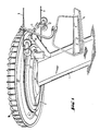
- FIG. 1 shows a column 1 as a carrier or as a bearing for a cable pulley 2.
- the cable deflection pulley 2 is formed on its underside with a guide groove 21 for the carrying and conveying cable 3.
- Guide or guide rollers 12 are also mounted on the carrier 1 by means of a frame 11. Armchairs 5 are coupled to the carrying and conveyor rope 3.
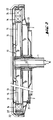
- the cable deflection disk 2 is formed on its outer peripheral edge with an upwardly projecting flange 22, on the inside of which at least one group of electromagnets 24 or permanent magnets 24 'arranged next to one another is carried. Furthermore, a disk-shaped plate 13 is fastened to the carrier 1, on the outer circumference of which a plurality of ring-shaped electromagnets 14 are arranged. The electromagnets 14 are connected to a supply and control circuit via control lines 15. The cable pulley 2 can be rotated relative to the carrier 1 by means of a bearing 25.
- This arrangement creates a magnetic motor, the stator of which is formed by the disk 13 with the electromagnet 14 and the rotor of which is formed by the rope deflection disk 2 with the magnets 24, 24 '.
- the rotation of the rope deflection disk 2 is brought about by the fact that a rotating magnetic field is generated by successive excitation of the electromagnets 14 arranged next to one another in a ring, through which the magnets 24, 24 'are attracted or repelled, as a result of which the cable deflection disk 2 serving as a rotor is rotated.
- the cable deflection pulley 2 serves as a drive for the carrying and conveying cable 3.
- a cover 16 is provided above the cable deflection pulley 2.
- the rotating field can also be generated by the electromagnets 24 arranged on the cable deflection disk 2, wherein permanent magnets can also be arranged on the disk 13.
- the electromagnets are fed via slip rings.
- a supporting structure can be provided instead of a support column, which is attached to the ceiling of the station.
- the cable deflection disc is coupled to the rotor of the drive motor via an optionally flexible shaft so that it can be taken along.
Landscapes
- Engineering & Computer Science (AREA)
- Transportation (AREA)
- Mechanical Engineering (AREA)
- Pulleys (AREA)
- Ropes Or Cables (AREA)
- Dynamo-Electric Clutches, Dynamo-Electric Brakes (AREA)
- Unwinding Of Filamentary Materials (AREA)
- Non-Mechanical Conveyors (AREA)
- Hydroponics (AREA)
- Storing, Repeated Paying-Out, And Re-Storing Of Elongated Articles (AREA)
- Other Liquid Machine Or Engine Such As Wave Power Use (AREA)
- Forwarding And Storing Of Filamentary Material (AREA)
- Flexible Shafts (AREA)
- Lift-Guide Devices, And Elevator Ropes And Cables (AREA)
- Superconductors And Manufacturing Methods Therefor (AREA)
- Saccharide Compounds (AREA)
- Compositions Of Oxide Ceramics (AREA)
- Control Of Combustion (AREA)
- Steering Controls (AREA)
Abstract
Seilbahnanlage mit in der Talstation und in der Bergstation angeordneten Seilumlenkscheiben (2), deren mindestens eine angetrieben ist, und mit einem um die Seilumlenkscheiben (2) gelegten und über Führungs- bzw. Ablenkrollen (12) geleiteten Trag- und Förderseil (3) für die Bewegung von Fahrbetriebsmitteln, wie Sesseln (5). Dabei bildet die Seilumlenkscheibe (2) den Rotor des Antriebsmotors, insbesondere eines Magnetmotors, bzw. ist sie mit diesem unmittelbar auf Mitnahme gekuppelt. 
Description
Die Erfindung betrifft eine Seilbahnanlage mit in der Talstation und in der Bergstation angeordneten Seilumlenkscheiben, wobei mindestens eine Seilumlenkscheibe mit einem Antrieb ausgebildet ist, und mit einem um die Seilumlenkscheiben und über Leit- bzw. Ablenkrollen geführten Trag- und Förderseil für die Bewegung von Fahrbetriebsmitteln, wie Sesseln, Kabinen und anderen Transportmitteln, z.B. Kübeln.The invention relates to a cable car system with rope deflection disks arranged in the valley station and in the mountain station, at least one rope deflection disk being designed with a drive, and with a carrying and conveying rope for the movement of driving means, which is guided around the rope deflection disks and via guide or deflection rollers. such as armchairs, cabins and other means of transport, e.g. Buckets.
Bei bekannten derartigen Seilbahnanlagen ist entweder in der Talstation oder in der Bergstation ein Antriebsmotor vorgesehen, durch welchen die Seilumlenkscheibe über ein Getriebe und eine Kupplung antreibbar ist. Ein Getriebe ist deshalb erforderlich, um die Umdrehungsgeschwindigkeit der Seilumlenkscheibe zu reduzieren, mit welcher das Trag- und Förderseil bewegt wird. Ein derartiger Antrieb ist jedoch deshalb nachteilig, da zusätzlich zum Elektromotor das Getriebe und eine Kupplung vorgesehen sein müssen, welche störungsanfällgig sind, da weiters durch das Getriebe Geräuschentwicklungen bedingt werden und da schließlich diese Bauteile Abnützungen unterliegen, weswegen sie gleichfalls störungsanfällig sind.In known cable car systems of this type, a drive motor is provided either in the valley station or in the mountain station, by means of which the cable deflection pulley can be driven via a gear and a clutch. A gearbox is therefore required to reduce the speed of rotation of the rope deflection pulley with which the carrying and conveyor rope is moved. However, such a drive is disadvantageous because, in addition to the electric motor, the gearbox and a clutch must be provided, which are susceptible to malfunction, since noise also results from the gearbox and because these components are subject to wear, which is why they are also prone to failure.
Der gegenständlichen Erfindung liegt demnach die Aufgabe zugrunde, einen Antrieb für eine Seilbahnanlage zu schaffen, durch welche die vorstehend angeführten Nachteile bekannter Antriebe vermieden werden und durch welche noch weitere Vorteile erzielt werden. Dies wird erfindungsgemäß dadurch erzielt, daß die Seilumlenkscheibe den Rotor des Antriebsmotors, insbesondere eines Magnetmotors, bildet, bzw. mit diesem unmittelbar auf Mitnahme gekuppelt ist. Ein Magnetmotor besteht aus einem Stator und aus einem Rotor, wobei am Stator eine Gruppe von Elektromagneten angeordnet ist, welcher am Rotor eine Gruppe von Permanentmagneten oder Elektromagneten zugeordnet ist. Durch aufeinander folgende Erregung der nebeinander liegenden Elektromagneten des Stators wird ein sich drehendes Feld erzeugt, durch welches der Rotor verdreht wird.The object of the present invention is therefore to provide a drive for a cable car system by means of which the above-mentioned disadvantages of known drives are avoided and by which further advantages are achieved. This is achieved according to the invention in that the cable deflection disk forms the rotor of the drive motor, in particular a magnetic motor, or is coupled with it directly for driving. A magnetic motor consists of a stator and a rotor, a group of electromagnets being arranged on the stator and being assigned a group of permanent magnets or electromagnets on the rotor. Through each other following excitation of the electromagnets of the stator lying next to one another, a rotating field is generated, by means of which the rotor is rotated.
Durch die erfindungsgemäße Ausbildung der Seilumlenkscheibe als Rotor des Antriebsmotors bzw. durch unmittelbare Kupplung der Seilumlenkscheibe mit dem Rotor des Antriebsmotors kann auf die Anordnung eines Getriebes und einer Kupplung verzichtet werden. Hierdurch werden die durch ein Getriebe und eine Kupplung bedingten Nachteile, nämlich daß diese einer Abnützung unterliegen, daß sie einer Wartung bedürfen, daß durch ihren Betrieb Geräusche verursacht werden und daß für den Betrieb des Getriebes Öl benötitgt wird, vermieden. Ein Magnetmotor kann in einfacher Weise in seiner Umdrehungsgeschwindigkeit stufenlos gesteuert werden. Zudem kann niemals durch Bruch von Bauteilen ein Blockieren des Motors bedingt werden.Due to the inventive design of the rope deflection disk as the rotor of the drive motor or through direct coupling of the rope deflection disk with the rotor of the drive motor, the arrangement of a gear and a clutch can be dispensed with. This avoids the disadvantages caused by a transmission and a clutch, namely that they are subject to wear, that they require maintenance, that their operation causes noise and that oil is required for the operation of the transmission. The speed of rotation of a magnetic motor can be steplessly controlled in a simple manner. In addition, the motor can never be blocked due to component breakage.
Nach einem bevorzugten Ausführungsbeispiel ist an der Seilumlenkscheibe eine Gruppe von Permanentmagneten oder Elektromagneten angeordnet, welcher am Stator, der am Träger für diese Seilumlenkscheibe befestigt ist, ein Ring von Elektromagneten, durch welche ein sich drehendes Magnetfeld erzeugbar ist, zugeordnet ist. Es können jedoch auch am Rotor Elektromagneten vorgesehen sein, durch welche das Drehfeld erzeugbar ist. Vorzugsweise ist die Seilumlenkscheibe an ihrer Oberseite mit mindestens einer Gruppe von ringförmig angeordneten Magneten ausgebildet, welcher ein vom Träger für die Umlenkscheibe getragener Ring von Elektromagneten, durch welche ein sich drehendes Feld erzeugbar ist, zugeordnet ist, wobei die Oberseite der Seilumlenkscheibe durch ein kappenartiges Gehäuse umschlossen ist. Die mindestens eine Führungsrille für das Trag- und Förderseil kann dabei entweder am Außenumfang der Seilumlenscheibe oder an einem an ihrer Unterseite angeordneten zusätzlichen Ring vorgesehen sein.According to a preferred embodiment, a group of permanent magnets or electromagnets is arranged on the cable deflection disk, to which a ring of electromagnets by means of which a rotating magnetic field can be generated is assigned to the stator, which is fastened to the support for this cable deflection disk. However, electromagnets can also be provided on the rotor, by means of which the rotating field can be generated. Preferably, the cable deflection disk is formed on its upper side with at least one group of magnets arranged in a ring, to which a ring of electromagnets carried by the carrier for the deflecting plate, by means of which a rotating field can be generated, is assigned, the upper side of the cable deflecting plate by a cap-like housing is enclosed. The at least one guide groove for the carrying and conveying rope can be provided either on the outer circumference of the rope sheave or on an additional ring arranged on its underside.
Der Gegenstand der Erfindung ist nachstehend anhand eines in der Zeichnung dargestellten Ausführungsbeispiels näher erläutert. Es zeigen:
- Fig. 1 eine Seilumlenkscheibe mit einem erfindungsgemäßen Antrieb, in axonometrischer Darstellung, und
- Fig. 2 die Seilumlenkscheibe gemäß Fig. 1, in achsialem Schnitt.
- Fig. 1 shows a rope deflection plate with a drive according to the invention, in an axonometric view, and
- Fig. 2, the rope deflection sheave according to Fig. 1, in axial section.
In Fig.1 ist eine Säule 1 als Träger bzw. als Lager für eine Seilumlenscheibe 2 dargestellt. Die Seilumlenkscheibe 2 ist an ihrer Unterseite mit einer Führungsrille 21 für das Trag- und Förderseil 3 ausgebildet. Am Träger 1 sind weiters mittels eines Gestells 11 Führungs- bzw. Leitrollen 12 gelagert. An das Trag und Förderseil 3 sind Sessel 5 angekuppelt.1 shows a
Wie aus Fig.2 ersichtlich ist, ist die Seilumlenkscheibe 2 an ihrem äußeren Umfangsrand mit einem nach oben abragenden Flansch 22 ausgebildet, an dessen Innenseite mindestens eine Gruppe von nebeneinander angeordneten Elektromagneten 24 oder Permanentmagneten 24′ getragen ist. Am Träger 1 ist weiters eine scheibenförmige Platte 13 befestigt, an deren äußerem Umfang eine Vielzahl von ringförmig angeordneten Elektromagneten 14 angeordnet ist. Die Elektromagneten 14 sind über Steuerleitungen 15 mit einer Speise- und Steuerschaltung verbunden. Die Seilumlenscheibe 2 ist mittels eines Lagers 25 gegenüber dem Träger 1 verdrehbar.As can be seen from FIG. 2, the
Durch diese Anordnung ist ein Magnetmotor geschaffen, dessen Stator durch die Scheibe 13 mit dem Elektromagneten 14 und dessen Rotor durch die Seilumlenkscheibe 2 mit den Magneten 24, 24′ gebildet ist. Die Verdrehung der Seilumlenkscheibe 2 wird dadurch bewirkt, daß durch aufeinanderfolgende Erregung der ringförmig nebeneinander angeordneten Elektromagneten 14 ein sich drehendes Magnetfeld erzeugt wird, durch welches die Magneten 24, 24′ angezogen bzw. abgestoßen werden, wodurch die als Rotor dienende Seilumlenkscheibe 2 verdreht wird. Hierdurch dient die Seilumlenkscheibe 2 als Antrieb für das Trag- und Förderseil 3. Oberhalb der Seilumlenkscheibe 2 ist eine Abdeckung 16 vorgesehen.This arrangement creates a magnetic motor, the stator of which is formed by the
Ergänzend wird darauf verwiesen, daß das sich drehende Feld auch durch die an der Seilumlenkscheibe 2 angeordneten Elektromagneten 24 erzeugt werden kann, wobei auch auf der Scheibe 13 Permanentmagneten angeordnet sein können. Dabei erfolgt die Speisung der Elektromagneten über Schleifringe. Weiters kann anstelle einer Tragsäule ein Traggerüst vorgesehen sein, welches an der Decke der Station befestigt ist.In addition, reference is made to the fact that the rotating field can also be generated by the
Eine weitere Variante besteht darin, daß die Seilumlenkscheibe mit dem Rotor des Antriebsmotors über eine gegebenenfalls biegsame Welle unmittelbar auf Mitnahme gekuppelt ist.Another variant is that the cable deflection disc is coupled to the rotor of the drive motor via an optionally flexible shaft so that it can be taken along.
Claims (4)
Applications Claiming Priority (2)
| Application Number | Priority Date | Filing Date | Title |
|---|---|---|---|
| AT267/89 | 1989-02-08 | ||
| AT0026789A AT394168B (en) | 1989-02-08 | 1989-02-08 | ROPEWAY SYSTEM |
Publications (3)
| Publication Number | Publication Date |
|---|---|
| EP0381920A2 true EP0381920A2 (en) | 1990-08-16 |
| EP0381920A3 EP0381920A3 (en) | 1991-03-20 |
| EP0381920B1 EP0381920B1 (en) | 1995-03-08 |
Family
ID=3485996
Family Applications (1)
| Application Number | Title | Priority Date | Filing Date |
|---|---|---|---|
| EP89890324A Expired - Lifetime EP0381920B1 (en) | 1989-02-08 | 1989-12-18 | Cableway installation |
Country Status (17)
| Country | Link |
|---|---|
| US (1) | US5024162A (en) |
| EP (1) | EP0381920B1 (en) |
| JP (2) | JPH02248502A (en) |
| KR (1) | KR0160775B1 (en) |
| AT (2) | AT394168B (en) |
| AU (1) | AU623486B2 (en) |
| CA (1) | CA2008691C (en) |
| CZ (1) | CZ284444B6 (en) |
| DE (1) | DE58909093D1 (en) |
| ES (1) | ES2070193T3 (en) |
| FI (1) | FI110590B (en) |
| IN (1) | IN172141B (en) |
| NO (1) | NO171356C (en) |
| NZ (1) | NZ232034A (en) |
| RU (1) | RU2041097C1 (en) |
| SE (1) | SE9000198L (en) |
| SK (1) | SK278821B6 (en) |
Families Citing this family (10)
| Publication number | Priority date | Publication date | Assignee | Title |
|---|---|---|---|---|
| US5783895A (en) * | 1994-04-07 | 1998-07-21 | Kone Oy | Elevator motor with flat construction |
| ES2144055T3 (en) * | 1993-06-28 | 2000-06-01 | Kone Corp | ELEVATOR MACHINERY. |
| FI114419B (en) * | 1994-04-07 | 2004-10-15 | Kone Corp | The elevator machinery |
| FI93340C (en) * | 1993-06-28 | 1995-03-27 | Kone Oy | The elevator machine |
| AT404819B (en) * | 1996-01-25 | 1999-03-25 | Waagner Biro Ag | Shuttle cableway with cable drive at both termini |
| DE19721366A1 (en) * | 1997-05-22 | 1998-11-26 | Bosch Gmbh Robert | Circuit for testing serial circuit comprising switch and load |
| AT507380B1 (en) * | 2008-10-09 | 2010-09-15 | Innova Patent Gmbh | ARMCHAIR FOR ARMCHAIR |
| JP5455736B2 (en) * | 2010-03-25 | 2014-03-26 | 日本ケーブル株式会社 | Cableway prime mover |
| JP6422770B2 (en) * | 2014-12-26 | 2018-11-14 | 日本ケーブル株式会社 | Fixed circulation cableway pulley cover |
| CN105172799A (en) * | 2015-09-21 | 2015-12-23 | 李先登 | Chain rope power transmission mode of sightseeing cable car |
Family Cites Families (15)
| Publication number | Priority date | Publication date | Assignee | Title |
|---|---|---|---|---|
| DE152583C (en) * | ||||
| DE906719C (en) * | 1939-04-18 | 1954-03-18 | Hermann Papst | Arrangement of the power transmission means for external rotor motors |
| US2677331A (en) * | 1949-07-26 | 1954-05-04 | Bridger Ski Lift Inc | Ski lift |
| US2938472A (en) * | 1955-04-18 | 1960-05-31 | Tiegel Ernest George | Aerial tramways |
| US4003314A (en) * | 1975-04-25 | 1977-01-18 | Pearson William F | Ski lift monitoring |
| FR2514094A1 (en) * | 1981-10-07 | 1983-04-08 | Gimar | Self-drive tensioning pulley - has variable speed hydraulic motor on both pulley flanges |
| US4624617A (en) * | 1984-10-09 | 1986-11-25 | David Belna | Linear induction semiconductor wafer transportation apparatus |
| US4662282A (en) * | 1985-03-13 | 1987-05-05 | Hitachi Kiden Kogyo Kabushiki Kaisha | Switching device for pneumatic conveyance linear motor actuated |
| SU1350082A1 (en) * | 1986-04-21 | 1987-11-07 | Специальное конструкторское бюро магнитной гидродинамики Института физики АН ЛатвССР | Conveyer magnetofriction drive |
| US4781286A (en) * | 1986-11-12 | 1988-11-01 | Automated Manufacturing Systems, Inc. | Power and free roller conveyor |
| JP2642391B2 (en) * | 1988-03-31 | 1997-08-20 | 株式会社東芝 | Cableway drive |
| JPH0232731A (en) * | 1988-07-16 | 1990-02-02 | Chubu Seimitsu:Kk | Motor structure |
| US4949000A (en) * | 1988-07-18 | 1990-08-14 | Mueller And Smith, Lpa | D.C. motor |
| JPH0260873A (en) * | 1988-08-25 | 1990-03-01 | Nippon Cable Co Ltd | Linear motor type prime mover for cableway |
| US4920892A (en) * | 1988-11-07 | 1990-05-01 | Roman Pesek | Portable rope tow |
-
1989
- 1989-02-08 AT AT0026789A patent/AT394168B/en not_active IP Right Cessation
- 1989-12-18 EP EP89890324A patent/EP0381920B1/en not_active Expired - Lifetime
- 1989-12-18 ES ES89890324T patent/ES2070193T3/en not_active Expired - Lifetime
- 1989-12-18 DE DE58909093T patent/DE58909093D1/en not_active Expired - Lifetime
- 1989-12-18 AT AT89890324T patent/ATE119479T1/en not_active IP Right Cessation
- 1989-12-20 IN IN349/BOM/89A patent/IN172141B/en unknown
-
1990
- 1990-01-08 NZ NZ232034A patent/NZ232034A/en unknown
- 1990-01-19 JP JP2008522A patent/JPH02248502A/en active Pending
- 1990-01-19 SE SE9000198A patent/SE9000198L/en not_active Application Discontinuation
- 1990-01-22 CZ CS90306A patent/CZ284444B6/en not_active IP Right Cessation
- 1990-01-22 SK SK306-90A patent/SK278821B6/en not_active IP Right Cessation
- 1990-01-26 CA CA002008691A patent/CA2008691C/en not_active Expired - Lifetime
- 1990-01-31 RU SU904742940A patent/RU2041097C1/en active
- 1990-02-01 AU AU48955/90A patent/AU623486B2/en not_active Expired
- 1990-02-02 US US07/474,457 patent/US5024162A/en not_active Expired - Lifetime
- 1990-02-06 NO NO900572A patent/NO171356C/en not_active IP Right Cessation
- 1990-02-07 FI FI900595A patent/FI110590B/en active IP Right Grant
- 1990-02-07 KR KR1019900001458A patent/KR0160775B1/en not_active Expired - Fee Related
-
1998
- 1998-06-01 JP JP003795U patent/JPH1157U/en active Pending
Also Published As
| Publication number | Publication date |
|---|---|
| NO900572D0 (en) | 1990-02-06 |
| KR0160775B1 (en) | 1998-12-01 |
| AT394168B (en) | 1992-02-10 |
| AU4895590A (en) | 1990-08-16 |
| ES2070193T3 (en) | 1995-06-01 |
| EP0381920A3 (en) | 1991-03-20 |
| US5024162A (en) | 1991-06-18 |
| JPH02248502A (en) | 1990-10-04 |
| CS9000306A2 (en) | 1991-07-16 |
| NZ232034A (en) | 1992-06-25 |
| KR900012830A (en) | 1990-09-01 |
| JPH1157U (en) | 1999-04-09 |
| AU623486B2 (en) | 1992-05-14 |
| EP0381920B1 (en) | 1995-03-08 |
| SE9000198L (en) | 1990-08-09 |
| DE58909093D1 (en) | 1995-04-13 |
| NO171356B (en) | 1992-11-23 |
| ATE119479T1 (en) | 1995-03-15 |
| NO900572L (en) | 1990-08-09 |
| NO171356C (en) | 1993-03-03 |
| CA2008691A1 (en) | 1990-08-08 |
| FI110590B (en) | 2003-02-28 |
| IN172141B (en) | 1993-04-17 |
| SE9000198D0 (en) | 1990-01-19 |
| CA2008691C (en) | 1998-11-24 |
| ATA26789A (en) | 1991-08-15 |
| SK278821B6 (en) | 1998-03-04 |
| FI900595A0 (en) | 1990-02-07 |
| RU2041097C1 (en) | 1995-08-09 |
| CZ284444B6 (en) | 1998-11-11 |
Similar Documents
| Publication | Publication Date | Title |
|---|---|---|
| DE3242541C2 (en) | ||
| EP0381920A2 (en) | Cableway installation | |
| DE19801767C1 (en) | centrifuge | |
| EP2441638A1 (en) | Cable car system | |
| EP0355084A1 (en) | Cableway installation having return pulleys in both the lower and the higher station | |
| EP1489033A1 (en) | Elevator with two cars arranged one above the other in the same hoistway | |
| DE9304210U1 (en) | Storage and retrieval machine | |
| WO1998056706A1 (en) | Drive mechanism for escalators or moving walkways | |
| EP3257802A1 (en) | Shaft conveyer system for the mining industry | |
| DE4008229A1 (en) | Lifting mechanism for vehicle window - has two cable drives coupled by meshing drive pulleys | |
| DE2518753B2 (en) | Two-room shaft hoisting machine, in particular decoiler and further reel | |
| DE3707990A1 (en) | Retarding disc conveyor for the continuous conveying of suspensions | |
| DE2652637C3 (en) | Drive machine for the pull rope of a train | |
| DD221987A1 (en) | ROTARY ACTUATOR DRIVE, ESPECIALLY FOR TURNING CRANES WITH WHOLESALE SHAFT BEARINGS | |
| DE29816005U1 (en) | Shaft conveyor system with drum winch | |
| EP1574472B1 (en) | Elevator system with driving gear incorporated in the counterweight | |
| AT405733B (en) | Funicular railway | |
| DE69300033T2 (en) | Electric hoist. | |
| DD159290A1 (en) | FULLY AUTOMATIC POINTING DEVICE | |
| EP1089935A1 (en) | Hoist drive | |
| DE102011103553A1 (en) | Transport system for conveying transport goods i.e. food products, from loading point to delivery point, has transmission units for transferring motive force from drive units to conveyer, where drive units are arranged over conveyer | |
| DE3034362A1 (en) | BELT DRIVE FOR BELT CONVEYOR | |
| DE102011106133A1 (en) | Device for transporting containers, has conveyor unit having revolving conveyor, which contacts side wall of containers for transporting container in predetermined transport direction | |
| DE19752227A1 (en) | Preassembled elevator shaft | |
| DE1112201B (en) | Device for illuminating large areas by means of several adjustable lamp holders |
Legal Events
| Date | Code | Title | Description |
|---|---|---|---|
| PUAI | Public reference made under article 153(3) epc to a published international application that has entered the european phase |
Free format text: ORIGINAL CODE: 0009012 |
|
| AK | Designated contracting states |
Kind code of ref document: A2 Designated state(s): AT CH DE ES FR IT LI SE |
|
| PUAL | Search report despatched |
Free format text: ORIGINAL CODE: 0009013 |
|
| AK | Designated contracting states |
Kind code of ref document: A3 Designated state(s): AT CH DE ES FR IT LI SE |
|
| RHK1 | Main classification (correction) |
Ipc: B61B 12/10 |
|
| 17P | Request for examination filed |
Effective date: 19910422 |
|
| 17Q | First examination report despatched |
Effective date: 19920708 |
|
| ITF | It: translation for a ep patent filed | ||
| GRAA | (expected) grant |
Free format text: ORIGINAL CODE: 0009210 |
|
| AK | Designated contracting states |
Kind code of ref document: B1 Designated state(s): AT CH DE ES FR IT LI SE |
|
| REF | Corresponds to: |
Ref document number: 119479 Country of ref document: AT Date of ref document: 19950315 Kind code of ref document: T |
|
| ET | Fr: translation filed | ||
| REF | Corresponds to: |
Ref document number: 58909093 Country of ref document: DE Date of ref document: 19950413 |
|
| ITF | It: translation for a ep patent filed | ||
| REG | Reference to a national code |
Ref country code: ES Ref legal event code: FG2A Ref document number: 2070193 Country of ref document: ES Kind code of ref document: T3 |
|
| PLBE | No opposition filed within time limit |
Free format text: ORIGINAL CODE: 0009261 |
|
| STAA | Information on the status of an ep patent application or granted ep patent |
Free format text: STATUS: NO OPPOSITION FILED WITHIN TIME LIMIT |
|
| 26N | No opposition filed | ||
| REG | Reference to a national code |
Ref country code: FR Ref legal event code: TP |
|
| PG25 | Lapsed in a contracting state [announced via postgrant information from national office to epo] |
Ref country code: IT Free format text: LAPSE BECAUSE OF NON-PAYMENT OF DUE FEES;WARNING: LAPSES OF ITALIAN PATENTS WITH EFFECTIVE DATE BEFORE 2007 MAY HAVE OCCURRED AT ANY TIME BEFORE 2007. THE CORRECT EFFECTIVE DATE MAY BE DIFFERENT FROM THE ONE RECORDED. Effective date: 20051218 |
|
| PGFP | Annual fee paid to national office [announced via postgrant information from national office to epo] |
Ref country code: CH Payment date: 20081223 Year of fee payment: 20 |
|
| PGFP | Annual fee paid to national office [announced via postgrant information from national office to epo] |
Ref country code: AT Payment date: 20081219 Year of fee payment: 20 Ref country code: ES Payment date: 20081024 Year of fee payment: 20 |
|
| PGFP | Annual fee paid to national office [announced via postgrant information from national office to epo] |
Ref country code: SE Payment date: 20081211 Year of fee payment: 20 |
|
| PGFP | Annual fee paid to national office [announced via postgrant information from national office to epo] |
Ref country code: FR Payment date: 20081031 Year of fee payment: 20 |
|
| PGFP | Annual fee paid to national office [announced via postgrant information from national office to epo] |
Ref country code: DE Payment date: 20090408 Year of fee payment: 20 |
|
| REG | Reference to a national code |
Ref country code: CH Ref legal event code: PL |
|
| REG | Reference to a national code |
Ref country code: ES Ref legal event code: FD2A Effective date: 20091219 |
|
| PG25 | Lapsed in a contracting state [announced via postgrant information from national office to epo] |
Ref country code: ES Free format text: LAPSE BECAUSE OF EXPIRATION OF PROTECTION Effective date: 20091219 |
|
| PGFP | Annual fee paid to national office [announced via postgrant information from national office to epo] |
Ref country code: IT Payment date: 20081030 Year of fee payment: 20 |
|
| PGRI | Patent reinstated in contracting state [announced from national office to epo] |
Ref country code: IT Effective date: 20091201 |