EP0381976A2 - Elément chauffant - Google Patents
Elément chauffant Download PDFInfo
- Publication number
- EP0381976A2 EP0381976A2 EP19900101163 EP90101163A EP0381976A2 EP 0381976 A2 EP0381976 A2 EP 0381976A2 EP 19900101163 EP19900101163 EP 19900101163 EP 90101163 A EP90101163 A EP 90101163A EP 0381976 A2 EP0381976 A2 EP 0381976A2
- Authority
- EP
- European Patent Office
- Prior art keywords
- heating coil
- heating element
- heating
- carrier body
- element according
- Prior art date
- Legal status (The legal status is an assumption and is not a legal conclusion. Google has not performed a legal analysis and makes no representation as to the accuracy of the status listed.)
- Granted
Links
Images

Classifications
-
- H—ELECTRICITY
- H05—ELECTRIC TECHNIQUES NOT OTHERWISE PROVIDED FOR
- H05B—ELECTRIC HEATING; ELECTRIC LIGHT SOURCES NOT OTHERWISE PROVIDED FOR; CIRCUIT ARRANGEMENTS FOR ELECTRIC LIGHT SOURCES, IN GENERAL
- H05B3/00—Ohmic-resistance heating
- H05B3/40—Heating elements having the shape of rods or tubes
- H05B3/42—Heating elements having the shape of rods or tubes non-flexible
- H05B3/46—Heating elements having the shape of rods or tubes non-flexible heating conductor mounted on insulating base
-
- H—ELECTRICITY
- H05—ELECTRIC TECHNIQUES NOT OTHERWISE PROVIDED FOR
- H05B—ELECTRIC HEATING; ELECTRIC LIGHT SOURCES NOT OTHERWISE PROVIDED FOR; CIRCUIT ARRANGEMENTS FOR ELECTRIC LIGHT SOURCES, IN GENERAL
- H05B3/00—Ohmic-resistance heating
- H05B3/02—Details
- H05B3/06—Heater elements structurally combined with coupling elements or holders
-
- H—ELECTRICITY
- H05—ELECTRIC TECHNIQUES NOT OTHERWISE PROVIDED FOR
- H05B—ELECTRIC HEATING; ELECTRIC LIGHT SOURCES NOT OTHERWISE PROVIDED FOR; CIRCUIT ARRANGEMENTS FOR ELECTRIC LIGHT SOURCES, IN GENERAL
- H05B3/00—Ohmic-resistance heating
- H05B3/10—Heating elements characterised by the composition or nature of the materials or by the arrangement of the conductor
- H05B3/16—Heating elements characterised by the composition or nature of the materials or by the arrangement of the conductor the conductor being mounted on an insulating base
Definitions
- the invention relates to a heating element, in particular for toasters, with a carrier body, with a heating coil held by the carrier body and with connecting elements which connect a power supply wire at each end to the heating coil.
- the invention further relates to a method for producing a heating element of the aforementioned type.
- the heating coil is first wound on a winding machine, then one or more turns of the heating coil are bent open at the end, that is to say end spiral, and connected to the power connection wire by means of a crimp connection.
- the heating coil is fixed to the carrier body, which can be, for example, a ceramic tube onto which the heating coil is pushed on the outside, or a quartz tube into which the heating coil is drawn in on the inside, in that either the bent one is bent Part of the heating coil is bent and hooked into a wall of the carrier body or a connector, usually in the form of a rivet, is attached via a crimp connection.
- the carrier body can be, for example, a ceramic tube onto which the heating coil is pushed on the outside, or a quartz tube into which the heating coil is drawn in on the inside, in that either the bent one is bent Part of the heating coil is bent and hooked into a wall of the carrier body or a connector, usually in the form of a rivet, is attached via a crimp connection.
- the invention is therefore based on the object of improving a heating element of the type described at the outset and a method for producing such such that good electrical contact between the power supply wires and the heating coil is ensured and that the heating element can be produced as simply as possible.
- connection elements directly with at least one end-lying turn
- a permanent and reliable electrical contact is established between the connection elements and the heating coil and that, moreover, the connection between the connection elements and the heating coil is made no bending of the heating coil required, so that this complex operation is saved.
- Holding the heating coil on the carrier body with the end elements is particularly advantageous when the heating coil is held tensioned on the carrier body in the direction of its longitudinal axis.
- the tensioned holding of the heating coil can be easily realized by the connection elements supported on the carrier body.
- connection elements In order to make it easy to support the connection elements on the support body, it is provided that the connection elements have extensions which are supported on the support body.
- connection elements over the extensions is achieved in a particularly simple manner in that the extensions protrude over a peripheral surface of the heating coil facing the carrier body in the direction of the carrier body and in particular extend in the direction transverse to a longitudinal axis of the heating coil.
- an alternative provides that the extensions protrude outward beyond the heating coil and a second alternative that the extensions extend inwards towards the longitudinal axis
- the heating coil ends at both ends with a last turn, that is to say if, after winding the heating coil, only cutting off after each last turn and therefore no further operations, in particular no bending of the last turn have to take place on the heating coil itself. This is also of great advantage, since otherwise there is always the risk that the heating coil warps unevenly.
- the invention is based on the fact that the heating coil is welded to the connecting elements with at least one end turn. It is particularly expedient here if the connection elements are welded to the last turn, preferably the connection elements are even welded to the last two to five turns of the heating coil or even better the last two to three turns of the heating coil.
- connection elements are provided with a welding lug.
- this welding lug is designed such that it is essentially adapted to the curvature of the turns of the heating coil.
- the welding lug rests on the circumferential side of the turns of the heating coil opposite the carrier body, so that when the heating coil is mounted on the carrier body it is not hindered by the welding lug.
- the connecting elements do not extend beyond the circumferential side of the heating coil facing the carrier body. This makes it possible to weld the connection elements on the support body before attaching the heating coil, the extensions being in the assembly position, that is to say also not extending beyond the circumferential side of the heating coil facing the support body, and at least in the case of a connection element only after the attachment of the To bend the heating coil on the carrier body the extensions into a holding position in which they extend beyond the peripheral side of the heating coil facing the carrier body.
- the current supply wires can be held on the connection elements via crimp connections.
- the connection elements are welded to the current supply leads.
- the connection elements are advantageously designed such that they have a connection lug for the current supply wires.
- the design of the carrier body has not been specified in detail. In the context of the present invention, however, it has proven particularly expedient if the carrier body is elongated, in particular if the carrier body is a tube.
- a ceramic tube is preferably used in the heating elements according to the invention, on the outer circumferential side of which the heating coil is then arranged, or a quartz tube, on the inside of which, ie on the inner circumferential side, the heating coil is arranged.
- the extensions are supported on the end side of the carrier body, that is to say they preferably rest on the end faces thereof.
- connection element is made of scale-free material, the material preferably being more heat-resistant than the heating coil. This has proven to be particularly useful when heating coils with a superficial oxidation layer are to be used which, because of their superficial oxidation layer, have the advantage that short circuits between individual turns can be avoided during operation.
- connection element has proven to be particularly favorable.
- the above-mentioned object is also achieved by a method for producing a heating element, in particular a heating element according to the above-mentioned exemplary embodiments, comprising a heating coil, a support body, a connection element and the power supply wires connected to it are solved in that the end of the heating coil is welded to the connection elements after winding, then drawn onto the carrier body and fixed with the connection elements.
- the connecting elements are bent from a mounting position in which they do not protrude over a peripheral side of the heating coil facing the carrier body into a holding position in which they at least partially over the peripheral side facing the carrier body Survive the heating coil.
- connection elements are bent from the mounting position into the holding position.
- both power supply wires are connected to the connection elements.
- the current guide wires are also welded to the connection elements.
- the heating coils Since in particular the mounting of the heating coils on the carrier body causes problems, preferably when the heating coils are not to be bent up at the end, it is within the scope of the present invention, it is particularly advantageous if the power supply wires are used as an aid when pulling the heating coil onto the carrier.
- the heating coil is pulled onto the carrier by pulling on a power supply wire.
- the simplest method for pulling the heating coil onto the carrier body provides that the extensions of the first connection element are bent into their holding position before the heating coil is pulled up, so that they can come into contact with the carrier body when they are pulled up. As the next step, the extensions of the second connection element are then bent over after being pulled into their holding position.
- a preferred embodiment of the heating element according to the invention provides that the heating coil is oxidized before being pulled onto the carrier body.
- heating coil is welded to the connection elements before oxidation.
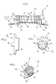
- a first embodiment of a heating element designated as a whole by 10 in FIG. 1, comprises an elongated ceramic tube 12 as the carrier body, which carries on an outer lateral surface 14 a heating coil 16 drawn onto the ceramic tube 12, which extends over the entire ceramic tube 12 from a first end 18 to extends to a second end 20 with its individual turns 22.
- the end-side three to four turns 22 preferably lie in the area of the first end 18 and the end-side three to four turns 22 in the area of the second end 20, while the turns 22 are spaced apart from one another.
- the heating coil 16 thus ends both in the area of the first end 18 and in the area of the second end 20 with the last turn 22 in each case.
- the end windings 22 which abut each other in the area of the first end 18 and in the area of the second end 20 are overlapped by a welding lug 24 of a connection element designated as a whole by 26 (FIG. 2).
- the welding lug 24 is adapted to a radius of curvature of the individual turns 22 of the heating coil 16 on the outside 28 thereof and preferably overlaps the end turns 22 essentially over their half circumference.
- the end-to-end three to four turns 22 of the heating coil 16 are welded to the welding lug 24, wherein, as can be seen from FIG. 4, a welding point 30 is preferably arranged in the center of the welding lug 24 and in the direction of a longitudinal axis 34 of the heating coil 16 and the ceramic tube 12 extends.
- the connecting element 26 then includes two projections 32, which in their holding position - shown in dashed lines in FIG. 3 - run in the radial direction to a longitudinal axis 34 of the ceramic tube 12 and the heating coil 16 on the longitudinal axis 34 and in their mounting position - drawn as a solid line in FIG. 3 - do not protrude inward beyond the outside 28 of the end turns 22 in the direction of the longitudinal axis 34, but are, for example, adapted to the curvature of the outside 28 or extend tangentially to it in a straight direction.
- the projections 32 bent in the holding position each rest on an end face 35 of the first end 18 or the second end 20 of the ceramic tube 12 and thus hold the heating coil 16 drawn onto the ceramic tube 12 in tension in the direction of the longitudinal axis 34 on the ceramic tube 12 clamped position.
- Each connecting element 26 further comprises on its side opposite the welding lug 24 a connecting lug 36 which, in the fully assembled state of the heating element 10, extends in the direction of the longitudinal axis 34 from the ends 18, 20 of the ceramic tube 12.
- This terminal lug 36 is preferably provided with a power supply wire 38.
- the power supply wire 38 then leads to the electrical connections for the heating element 1.
- the power supply wire 38 is preferably arranged on the connection lug 36 on a side opposite the heating coil 16 and welded to it.
- the connecting element 26 is made from scale-free material, in particular from a chromium-nickel compound.
- the heating element 10 according to the first exemplary embodiment is now installed in such a way that after the heating coil 16 has been wound, it is cut to the desired length.
- the end windings 22 are then welded to the respective welding lugs 24 of the connection elements 26, the extensions 32 still being aligned in the assembly position, as shown in FIG. 3.
- the current supply wires 38 are then welded to the respective connecting lugs 36 of the connecting elements 26.
- the extensions 32 are bent over from one of the connecting elements 26 into the holding position.
- the ceramic tube 12 is now inserted from the side into the heating coil, on which the connecting element 26 is welded, the extensions 32 of which are still in the assembly position. Consequently The ceramic tube 12 can be pushed through until, for example, the end face 35 of the second end 20 bears against the extensions 32 of the one connecting element 26 which are in the holding position.
- the current supply wire 38 of the connecting element 26 can now be pulled, the extensions 32 of which are still in the installed position.
- the heating coil 16 can be held in place via the current supply wire 38 of the connecting element 26, the extensions of which are already in the holding position. This allows the heating coil 16 to be pulled so far that the extensions 32 in the mounting position come to lie in the direction of the longitudinal axis 34 in front of the end face 35, so that these extensions 32 can be bent into the holding position.
- the heating coil 16 can pull the two connection elements 26 so far that their extensions 32, which are in the holding position, rest on the end faces 35 in the region of the first end 18 and the second end 20 on the ceramic tube 12 and consequently the heating coil 16 is fixed on this.
- the fully assembled heating element 10 can be installed in this form in a corresponding device, for example a toaster.
- FIGS. 5 to 7 the same parts, insofar as they are provided with the same reference numerals, are only provided with an additional line. Regarding their description can therefore be referred to the first embodiment.
- the carrier body is not designed as a ceramic tube 12, but rather as a quartz tube 40, in which the heating coil 16' is arranged on the inside.
- the respective end turns 22 'of the heating coil 16' are in the fully assembled state of the heating element 10 'also welded with welding lugs 24' of the connecting elements 26 ', in this embodiment the welding lugs 24' are arranged inside the heating coil 16 'and thereby in their Curvature, as can be seen for example from Fig. 6, the curvature of an inside 42 of the heating coil 16 'are adapted.
- connection elements 26 'extensions 32' are drawn in their mounting position, as drawn in Fig. 6, bent such that they are as possible within the heating coil 16 ', but at least not beyond an outside 28' of the heating coil 16 ' .
- the extensions 32 ' in contrast to the first exemplary embodiment, are not bent radially inward to the longitudinal axis 34', but point with respect to the longitudinal axis 34 'in the radial direction outwards, protruding so far in the radial direction that they protrude can be supported on an end face 44 of the quartz tube 40.
- the power supply wires 38 'in the second embodiment are welded to the connecting lugs 36' also on the side opposite the windings 22 'of the heating coil 16', that is to say that the power supply wires 38 'in the second embodiment on the side of the longitudinal axis 34' of the Connection lugs 36 'are present.
- the procedure is now such that the heating coil 16' is first wound, with a simple cut off of the last winding in each case in the region of the two ends of the heating coil 16 '.
- the respective end windings 22 ' are welded to the welding lug 24' of the respective connecting element 26 ', so that at both ends of the heating coil 16' a connecting element 26 'with each of the heating coil 16' projecting terminal lug 36 'is welded.
- the next step is a welding of the power supply wires 38 'to the terminal lugs 36' and then a bending of the extensions 32 'in the holding position at one of the holding elements 26', while the other closing element 26 'still has extensions 32' bent into the mounting position.
- connection element 26 'welded power supply wire 38' is now inserted into the quartz tube 40 and pushed through this, this power supply wire 38 'serves as a tension element to the connection element 26' with the extensions 32 'bent in the mounting position through the quartz tube 40 so pull it far until the connecting element 26 'with its extensions 32' in the holding position rests on the end face 44, for example of the second end 48, on the quartz tube 40 and the extensions 32 'of the other connecting element 26' in the direction of the longitudinal axis 34 which are still in the mounting position 'Are pulled out of the quartz tube 40 so far that they stand in front of the first end 46 and can be bent into the holding position.
- the heating coil 16' is fixed in the quartz tube 40 by the fact that the extensions 32 'due to the internal stress of the heating coil 16' in the direction of the longitudinal axis 34 'against the end faces 44 of the quartz tube 40 on first end 46 and at the second end 48 are created.
Landscapes
- Resistance Heating (AREA)
- Sorption Type Refrigeration Machines (AREA)
- Electric Stoves And Ranges (AREA)
- General Induction Heating (AREA)
Applications Claiming Priority (2)
| Application Number | Priority Date | Filing Date | Title |
|---|---|---|---|
| DE3903961A DE3903961A1 (de) | 1989-02-10 | 1989-02-10 | Heizelement |
| DE3903961 | 1989-02-10 |
Publications (3)
| Publication Number | Publication Date |
|---|---|
| EP0381976A2 true EP0381976A2 (fr) | 1990-08-16 |
| EP0381976A3 EP0381976A3 (fr) | 1991-11-21 |
| EP0381976B1 EP0381976B1 (fr) | 1993-06-02 |
Family
ID=6373787
Family Applications (1)
| Application Number | Title | Priority Date | Filing Date |
|---|---|---|---|
| EP90101163A Expired - Lifetime EP0381976B1 (fr) | 1989-02-10 | 1990-01-20 | Elément chauffant |
Country Status (5)
| Country | Link |
|---|---|
| EP (1) | EP0381976B1 (fr) |
| AT (1) | ATE90172T1 (fr) |
| DE (3) | DE3903961A1 (fr) |
| DK (1) | DK0381976T3 (fr) |
| ES (1) | ES2042081T3 (fr) |
Cited By (5)
| Publication number | Priority date | Publication date | Assignee | Title |
|---|---|---|---|---|
| EP0627869A1 (fr) * | 1993-06-03 | 1994-12-07 | Seb S.A. | Dispositif de chauffage et de régulation d'une table vitrocéramique |
| FR2706111A1 (fr) * | 1993-06-03 | 1994-12-09 | Seb Sa | Dispositif chauffant pour table vitrocéramique. |
| EP0635992A3 (fr) * | 1989-01-27 | 1995-09-20 | Seb Sa | Element chauffant. |
| DE10161535A1 (de) * | 2001-12-10 | 2003-06-26 | Brigitte Wolf | Heizelement und Verfahren zur Herstellung eines Heizelements |
| US11530843B2 (en) | 2018-04-09 | 2022-12-20 | Zhejiang Prulde Electric Appliance Co., Ltd. | Heating core for hot air gun use and hot air gun |
Families Citing this family (3)
| Publication number | Priority date | Publication date | Assignee | Title |
|---|---|---|---|---|
| DE3925664A1 (de) * | 1989-08-03 | 1991-02-07 | Friedrich Wuerth Fa | Heizelement |
| DE4123266A1 (de) * | 1991-07-13 | 1993-01-21 | Braun Ag | Brotroester-isolierrohrheizung |
| FR2840760B1 (fr) * | 2002-06-05 | 2004-10-22 | Seb Sa | Element chauffant simplifie pour grille-pain |
Family Cites Families (6)
| Publication number | Priority date | Publication date | Assignee | Title |
|---|---|---|---|---|
| GB759946A (en) * | 1954-03-09 | 1956-10-24 | Emi Ltd | Improvements in or relating to electric resistance heating elements |
| US3253243A (en) * | 1961-08-07 | 1966-05-24 | Insto Gas Corp | Heater tube assembly |
| US3217279A (en) * | 1962-02-19 | 1965-11-09 | Wiegand Co Edwin L | Electric resistance heater |
| US3384852A (en) * | 1966-02-16 | 1968-05-21 | Btu Eng Corp | High temperature electrical furnace |
| DE7634006U1 (de) * | 1976-10-28 | 1978-04-20 | Bosch-Siemens Hausgeraete Gmbh, 7000 Stuttgart | Flachheizkoerper fuer einen elektrischen brotroester oder einen toaster |
| FR2642573B1 (fr) * | 1989-01-27 | 1993-09-17 | Seb Sa | Connecteur electrique pour element chauffant |
-
1989
- 1989-02-10 DE DE3903961A patent/DE3903961A1/de not_active Withdrawn
-
1990
- 1990-01-20 DE DE9090101163T patent/DE59001578D1/de not_active Expired - Fee Related
- 1990-01-20 DK DK90101163.5T patent/DK0381976T3/da active
- 1990-01-20 AT AT90101163T patent/ATE90172T1/de not_active IP Right Cessation
- 1990-01-20 EP EP90101163A patent/EP0381976B1/fr not_active Expired - Lifetime
- 1990-01-20 DE DE9007326U patent/DE9007326U1/de not_active Expired - Lifetime
- 1990-01-20 ES ES199090101163T patent/ES2042081T3/es not_active Expired - Lifetime
Cited By (5)
| Publication number | Priority date | Publication date | Assignee | Title |
|---|---|---|---|---|
| EP0635992A3 (fr) * | 1989-01-27 | 1995-09-20 | Seb Sa | Element chauffant. |
| EP0627869A1 (fr) * | 1993-06-03 | 1994-12-07 | Seb S.A. | Dispositif de chauffage et de régulation d'une table vitrocéramique |
| FR2706111A1 (fr) * | 1993-06-03 | 1994-12-09 | Seb Sa | Dispositif chauffant pour table vitrocéramique. |
| DE10161535A1 (de) * | 2001-12-10 | 2003-06-26 | Brigitte Wolf | Heizelement und Verfahren zur Herstellung eines Heizelements |
| US11530843B2 (en) | 2018-04-09 | 2022-12-20 | Zhejiang Prulde Electric Appliance Co., Ltd. | Heating core for hot air gun use and hot air gun |
Also Published As
| Publication number | Publication date |
|---|---|
| EP0381976A3 (fr) | 1991-11-21 |
| ATE90172T1 (de) | 1993-06-15 |
| DK0381976T3 (da) | 1993-10-04 |
| ES2042081T3 (es) | 1993-12-01 |
| DE3903961A1 (de) | 1990-08-16 |
| DE9007326U1 (de) | 1991-06-27 |
| DE59001578D1 (de) | 1993-07-08 |
| EP0381976B1 (fr) | 1993-06-02 |
Similar Documents
| Publication | Publication Date | Title |
|---|---|---|
| EP2181494B1 (fr) | Stator d'une machine électrique | |
| EP0491979A1 (fr) | Cathéter de stimulateur cardiaque avec deux pôles | |
| DE2617156B2 (de) | Klemmenplatte für Wicklungen | |
| DE102008060896A1 (de) | Spulentragevorrichtung und Herstellungsverfahren | |
| EP0381976B1 (fr) | Elément chauffant | |
| DE3404975A1 (de) | Stator fuer einen elektromotor sowie verfahren zum montieren eines stators | |
| DE60317749T2 (de) | Selbsthaltende Funkentstörungsdrossel für elektrischen Motor | |
| DE3787514T2 (de) | Kommutator. | |
| EP2831899B1 (fr) | Ensemble bobine | |
| EP0872005A1 (fr) | Lamelle pour machines electrodynamiques | |
| EP3129993A1 (fr) | Bobine de self antiparasite | |
| DE3310289A1 (de) | Elektrische spule sowie verfahren zum anschliessen von spulenenden | |
| DE102012106224A1 (de) | Endkappenanordnung für einen Elektromotor | |
| DE8911461U1 (de) | Anker für einen Elektromotor | |
| DE2936616C2 (de) | Verbinder für zwei Koaxialkabelenden | |
| DE19527653A1 (de) | Elektrodenwendel für Entladungslampen und Verfahren zur Herstellung einer derartigen Elektrodenwendel | |
| DE2829353A1 (de) | Rohrfoermige gluehlampe | |
| DE102019213538A1 (de) | Elektromotor | |
| DE3003240C2 (fr) | ||
| DE3127341C2 (de) | Transformatorspule | |
| EP1480290B1 (fr) | Dispositif de contact avec un fil de connexion | |
| DE19849683A1 (de) | Elektrische Drahtwicklung, insbesondere Heizdrahtwicklung | |
| EP1844479B1 (fr) | Corps de bobine | |
| CH534966A (de) | Kontaktstück zum lötfreien Anschliessen eines isolierten, elektrischen Leiters und Verwendung desselben | |
| DE102007029372A1 (de) | Wendel und Verfahren zur Herstellung einer Wendel |
Legal Events
| Date | Code | Title | Description |
|---|---|---|---|
| PUAI | Public reference made under article 153(3) epc to a published international application that has entered the european phase |
Free format text: ORIGINAL CODE: 0009012 |
|
| AK | Designated contracting states |
Kind code of ref document: A2 Designated state(s): AT BE DE DK ES FR GB IT |
|
| 17P | Request for examination filed |
Effective date: 19901201 |
|
| PUAL | Search report despatched |
Free format text: ORIGINAL CODE: 0009013 |
|
| AK | Designated contracting states |
Kind code of ref document: A3 Designated state(s): AT BE DE DK ES FR GB IT |
|
| 17Q | First examination report despatched |
Effective date: 19911105 |
|
| RAP3 | Party data changed (applicant data changed or rights of an application transferred) |
Owner name: FIRMA FRIEDRICH WUERTH |
|
| GRAA | (expected) grant |
Free format text: ORIGINAL CODE: 0009210 |
|
| AK | Designated contracting states |
Kind code of ref document: B1 Designated state(s): AT BE DE DK ES FR GB IT |
|
| REF | Corresponds to: |
Ref document number: 90172 Country of ref document: AT Date of ref document: 19930615 Kind code of ref document: T |
|
| ITF | It: translation for a ep patent filed | ||
| REF | Corresponds to: |
Ref document number: 59001578 Country of ref document: DE Date of ref document: 19930708 |
|
| ET | Fr: translation filed | ||
| REG | Reference to a national code |
Ref country code: DK Ref legal event code: T3 |
|
| GBT | Gb: translation of ep patent filed (gb section 77(6)(a)/1977) |
Effective date: 19930906 |
|
| REG | Reference to a national code |
Ref country code: ES Ref legal event code: FG2A Ref document number: 2042081 Country of ref document: ES Kind code of ref document: T3 |
|
| PGFP | Annual fee paid to national office [announced via postgrant information from national office to epo] |
Ref country code: BE Payment date: 19931217 Year of fee payment: 5 |
|
| PGFP | Annual fee paid to national office [announced via postgrant information from national office to epo] |
Ref country code: AT Payment date: 19940121 Year of fee payment: 5 |
|
| PGFP | Annual fee paid to national office [announced via postgrant information from national office to epo] |
Ref country code: DK Payment date: 19940331 Year of fee payment: 5 |
|
| PLBE | No opposition filed within time limit |
Free format text: ORIGINAL CODE: 0009261 |
|
| STAA | Information on the status of an ep patent application or granted ep patent |
Free format text: STATUS: NO OPPOSITION FILED WITHIN TIME LIMIT |
|
| 26N | No opposition filed | ||
| PG25 | Lapsed in a contracting state [announced via postgrant information from national office to epo] |
Ref country code: AT Effective date: 19950120 Ref country code: DK Effective date: 19950120 |
|
| REG | Reference to a national code |
Ref country code: DK Ref legal event code: EBP |
|
| PG25 | Lapsed in a contracting state [announced via postgrant information from national office to epo] |
Ref country code: BE Effective date: 19950131 |
|
| BERE | Be: lapsed |
Owner name: FIRMA FRIEDRICH WURTH Effective date: 19950131 |
|
| PGFP | Annual fee paid to national office [announced via postgrant information from national office to epo] |
Ref country code: GB Payment date: 19970113 Year of fee payment: 8 |
|
| PGFP | Annual fee paid to national office [announced via postgrant information from national office to epo] |
Ref country code: ES Payment date: 19970128 Year of fee payment: 8 |
|
| PG25 | Lapsed in a contracting state [announced via postgrant information from national office to epo] |
Ref country code: GB Free format text: LAPSE BECAUSE OF NON-PAYMENT OF DUE FEES Effective date: 19980120 |
|
| PG25 | Lapsed in a contracting state [announced via postgrant information from national office to epo] |
Ref country code: ES Free format text: LAPSE BECAUSE OF EXPIRATION OF PROTECTION Effective date: 19980121 |
|
| GBPC | Gb: european patent ceased through non-payment of renewal fee |
Effective date: 19980120 |
|
| REG | Reference to a national code |
Ref country code: ES Ref legal event code: FD2A Effective date: 20000601 |
|
| REG | Reference to a national code |
Ref country code: FR Ref legal event code: TP |
|
| PG25 | Lapsed in a contracting state [announced via postgrant information from national office to epo] |
Ref country code: IT Free format text: LAPSE BECAUSE OF NON-PAYMENT OF DUE FEES Effective date: 20050120 |
|
| PGFP | Annual fee paid to national office [announced via postgrant information from national office to epo] |
Ref country code: DE Payment date: 20080222 Year of fee payment: 19 |
|
| PGFP | Annual fee paid to national office [announced via postgrant information from national office to epo] |
Ref country code: FR Payment date: 20080102 Year of fee payment: 19 |
|
| PG25 | Lapsed in a contracting state [announced via postgrant information from national office to epo] |
Ref country code: DE Free format text: LAPSE BECAUSE OF NON-PAYMENT OF DUE FEES Effective date: 20090801 |
|
| REG | Reference to a national code |
Ref country code: FR Ref legal event code: ST Effective date: 20091030 |
|
| PG25 | Lapsed in a contracting state [announced via postgrant information from national office to epo] |
Ref country code: FR Free format text: LAPSE BECAUSE OF NON-PAYMENT OF DUE FEES Effective date: 20090202 |