EP0381999A2 - Kreisschere - Google Patents
Kreisschere Download PDFInfo
- Publication number
- EP0381999A2 EP0381999A2 EP19900101395 EP90101395A EP0381999A2 EP 0381999 A2 EP0381999 A2 EP 0381999A2 EP 19900101395 EP19900101395 EP 19900101395 EP 90101395 A EP90101395 A EP 90101395A EP 0381999 A2 EP0381999 A2 EP 0381999A2
- Authority
- EP
- European Patent Office
- Prior art keywords
- sheet metal
- crosspiece
- machine according
- circular
- supported
- Prior art date
- Legal status (The legal status is an assumption and is not a legal conclusion. Google has not performed a legal analysis and makes no representation as to the accuracy of the status listed.)
- Granted
Links
- 239000002184 metal Substances 0.000 title claims abstract description 41
- 238000005520 cutting process Methods 0.000 title claims abstract description 28
- 238000000605 extraction Methods 0.000 claims description 8
- 230000035515 penetration Effects 0.000 claims description 5
- 125000006850 spacer group Chemical group 0.000 claims description 5
- 239000012530 fluid Substances 0.000 description 2
- 238000003754 machining Methods 0.000 description 2
- 238000004519 manufacturing process Methods 0.000 description 2
- 239000002699 waste material Substances 0.000 description 2
- 241000252254 Catostomidae Species 0.000 description 1
- 238000007599 discharging Methods 0.000 description 1
- 239000000284 extract Substances 0.000 description 1
- 230000005484 gravity Effects 0.000 description 1
- 230000000670 limiting effect Effects 0.000 description 1
- 239000000463 material Substances 0.000 description 1
- 238000005192 partition Methods 0.000 description 1
- 238000003825 pressing Methods 0.000 description 1
- 230000000630 rising effect Effects 0.000 description 1
Images
Classifications
-
- B—PERFORMING OPERATIONS; TRANSPORTING
- B23—MACHINE TOOLS; METAL-WORKING NOT OTHERWISE PROVIDED FOR
- B23D—PLANING; SLOTTING; SHEARING; BROACHING; SAWING; FILING; SCRAPING; LIKE OPERATIONS FOR WORKING METAL BY REMOVING MATERIAL, NOT OTHERWISE PROVIDED FOR
- B23D33/00—Accessories for shearing machines or shearing devices
- B23D33/02—Arrangements for holding, guiding, and/or feeding work during the operation
- B23D33/04—Arrangements for holding, guiding, and/or feeding work during the operation for making circular cuts
Definitions
- the present invention relates to a machine for automatically cutting sheet metal disks.
- press dies allow to operate directly on the sheet metal band. However, only disks with a relatively small diameter and thickness can be cut, since very high operating pressures would otherwise be required, with an unacceptable increase in the costs of the press and of the dies themselves.
- disk cutting machines allow to cut disks even with a large diameter and thickness.
- Such machines require the sheet metal band to be cut beforehand into square plates from which the individual disks are to be obtained.
- Such machines in fact are generally provided with a pair of counter-rotating blades which are adapted to cut the sheet metal, which is rotated about an appropriate center so as to provide the circular cut.
- the movement is transmitted directly to the sheet metal plates and the blades are free; in other machines the blades are motorized and rotate the sheet metal.
- the need to operate on square panels of sheet metal is evident, since it is not possible to rotate the band.
- the preliminary cutting of the square panels increases the operating time and cost of the product. This machining furthermore entails greater waste, since the frame of sheet metal which is left over from the square plate after extraction of the disk cannot be used adequately.
- the aim of the present invention is to solve the above described problem by providing a machine which allows to cut even large-size disks from a band of sheet metal with reduced operating times and limited cutting pressures.
- a further object of the present invention is to provide a machine for cutting sheet metal disks which is simple in concept, safely reliable in operation and suitable for providing a fully automatic production line.
- the present machine for cutting sheet metal disks which is characterized in that it comprises a vertically movable bed which supports a circular template on which the sheet metal band to be machined is supported, a pair of circular blades which are rotatably supported at the opposite ends of a crosspiece which overlies said movable bed and are adapted to co-operate with said template to cut said sheet metal, and means adapted to rotate said crosspiece according to an axis which is vertically aligned with the axis of said circular template.
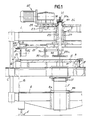
- the machine for cutting sheet metal disks has a fixed frame constituted by an upper table 1 and by a base 2 which are rigidly coupled, at the vertices, by four columns 3.
- a movable bed 5 is slidably guided on the columns 3 by means of sleeves 4.
- the frame is furthermore provided with adjustable feet 6.
- the movable bed 5 is rigidly associated with the stem of a double-action pneumatic cylinder 7.
- the cylinder 7 is fixed vertically, by means of a pair of half-rings 8a, 8b, to the base 2 of the fixed frame.
- the pneumatic cylinder 7 is preferably of the kind with multiple chambers, as illustrated in figure 2. Said chambers, defined by partitions inside the cylindrical jacket, are provided with a related piston 71 which is slidable therein and is rigidly associated with the stem of the cylinder; each piston 71 defines in particular a delivery chamber 7a and a return chamber 7b respectively connected to a delivery port M and a return port R. In this manner it is possible to use, during the thrust step, all the delivery chambers 7a or, according to the requirements, only a part thereof, subdividing the delivery with adapted valve means arranged on the delivery ports M, whereas during the retraction step a single return chamber 7b is conveniently used and the other chambers are kept in communication with the atmosphere by means of the related ports R.
- the movable bed 5 supports, by means of a plurality of spacers 9, a cutting template constituted by a male element in the shape of a circular plate 10 which is intended to support the sheet metal band 11 to be machined.
- the circular male element 10 is centered on a pivot 12 which rises from the bed 5.
- the sheet metal band 11 is guided along its longitudinal edges by related guides 13 at the entry to and exit from the circular male element 10. Said guides 13 furthermore lock the band 11 by means of securing elements not illustrated in the drawing.
- the male element 10 is peripherally surrounded by an extraction ring 14.
- Said extraction ring 14 is supported by columns 15 which slidably traverse the bed 5 and rest downwardly on the base 2.
- a threaded ring 16, screwed in an adjustable position on the cylinder 7, is adapted to limit the retraction stroke of the stem of said cylinder so as to align the male element 10 and the extractor 14 in idle position.
- the extraction ring 14 is furthermore provided with screw elements 17 which protrude vertically downward and are adapted to limit the lowering of said extractor during the rise of the bed 5.
- the circular male element 10 is adapted to co-operate in the cutting of the sheet metal 11, acting as fixed counter-blade, with a pair of circular blades 18 rotatably supported at the opposite ends of a crosspiece 19 which overlies said male element.
- Said crosspiece 19 is diametrically fixed to the lower end of a hollow shaft 20 which is rotatably mounted, by means of roller bearings 21, on the upper table 1 coaxially to the cylinder 7.
- the hollow shaft 20 is adapted to be rotated by a gearmotor element 22; the gearmotor actuates a pinion 23 which meshes with a toothed crown 24 mounted on the hollow shaft 20.
- the gearmotor 22 is supported by a plate 25 which is fixed to the table 1; said plate 25 is conveniently adapted to accommodate a second gearmotor in case of very heavy machining.
- the blades 18 are supported, with an axis of rotation which is radial to the hollow shaft 20, by a respective unit 26 which is fixed to the crosspiece 19 in a position which can be adjusted by means of a screw element 27.
- a pair of wheels 28 is mounted on the blade-holder unit 26 and engages the lower surface of the table 1. Said wheels 28 have the purpose of discharging the cutting thrust without subjecting to flexure the crosspiece 19, which merely transmits the rotation force of the gearmotor 22.
- the hollow shaft 20 is longitudinally traversed by the stem 29 of a single-action hydraulic cylinder 30 which is rigidly associated with the plate 25.
- the cylinder 30 is axially provided with an adjustment screw 31 adapted to abut, at the end of its stroke, against the stem 29; the cylinder is furthermore provided with a transverse pin 32 which engages a longitudinal groove of the stem so as to prevent the rotation thereof about its own axis.
- the cylinder 30 is provided, on the outlet hole 30a, with a valve, not illustrated in the drawing, which is adapted to lock the sliding of the stem 29 during the cutting step.
- the stem 29 is provided with a threaded tang 29a on which a plate 33 is screwed; said plate is adapted to stop the penetration of the blades 18 at the required height.
- the plate 33 furthermore co-operates to lock the band 11 during the cutting step by pressing said band against the surface of the male element 10.
- grip elements 35 such as for example electromagnets, suckers and the like, are fixed to the stem 29 by means of a transverse arm 34. Said grip elements 35 are intended to keep the disk cut from the sheet metal band 11 in contact with the plate 33, as described in greater detail hereafter.
- the operation of the machine for cutting sheet metal disks is easily understandable from the above description.
- the movable bed 5 is raised, by means of the actuation of the cylinder 7, so as to move the sheet metal 11, arranged on the male element 10, to press against the circular blades 18.
- the plate 33 acts as abutment and secures the sheet metal band 11 onto the male element 10.
- the blade-holder units 26 can be moved on the crosspiece 19 so as to provide the required play between the blades 18 and the male element 10.
- the penetration of the blades 18 can be such as to allow complete cutting.
- the disk is cut with a half turn of the crosspiece 19 which supports said blades.
- the crosspiece 19 is actuated by the gearmotor 22 which rotates the hollow shaft 20.
- the valve arranged at the output of the cylinder blocks the hydraulic fluid, so that the stem 20 is prevented from rising again and opposes the thrust imparted by the cylinder 7 to the male element 10.
- the penetration of the blades 18 is conveniently equal to half of the thickness.
- the hydraulic fluid is caused to exit from the cylinder 30 so that the stem 29 which bears the plate 33 can rise again until it abuts against the adjustment screw 31; the male element 10 then rises so as to complete the penetration of the blades 18 into the sheet metal 11 to execute a second half turn of the crosspiece 19.
- the disk is thus cut with a complete turn of the crosspiece 19.
- the bed 5 is again lowered and the ring 14 extracts the band from the male element 10.
- the extraction ring 14 in fact rests by gravity on said bed by means of the screw elements 17 which limit the lowering of the extractor.
- the extraction ring 14 abuts against the columns 15 and therefore removes the waste.
- the cut disk When the bed 5 descends together with the male element 10, the cut disk is kept in contact with the plate 33 by the grip elements 35. A space is thus created between the lower surface of the cut disk and the upper surface of the male element, and means adapted for the removal of said disk, such as a blade or the like, can be inserted into said space. When said removal means are in place, the grip elements 35 allow the disk to drop, and the disk is then removed.
- the described machine therefore allows to obtain the disks directly from the sheet metal band by rotating the cutting blade in a circular manner and by keeping said sheet metal motionless. In this manner the required pressure is small and the cutting time is sufficiently short.
- the machine allows to easily vary the size of the cut disks by radially moving the blades 18 and accordingly changing the male element 10.
- the replacement of the male element 10 with another one of a different diameter is facilitated by the spacers 9 interposed between the bed 5 and said male element 10.
- the centering pin 12 allows the different circular male elements to be correctly placed.
- the operating cycle is performed automatically by means of a single actuation.
- a device for removing the cut disk allows to provide a completely automatic production line by using an unwinding reel and a band straightener-feeder.
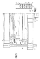
- Figure 3 illustrates a different embodiment of the machine, wherein the cutting template is provided by an annular female element 36.
- Said annular female element 36 is supported on the movable bed 5 by means of a pair of lateral spacers 37.
- the blades 18 are intended to co-operate, in order to cut the sheet metal, with the inner edge of the annular female element 36.
- the blades 18 conveniently have an axis of rotation which is slightly inclined downward toward the axis of the machine, as illustrated in the drawings by the line A.
- the cut disk drops in the region underlying the female element 36, from which it can be removed by means of suitable removal means.
- the materials employed, as well as the shapes and dimensions, may be any according to the requirements.
Landscapes
- Engineering & Computer Science (AREA)
- Mechanical Engineering (AREA)
- Perforating, Stamping-Out Or Severing By Means Other Than Cutting (AREA)
- Scissors And Nippers (AREA)
- Polishing Bodies And Polishing Tools (AREA)
- Mechanical Treatment Of Semiconductor (AREA)
- Processing Of Stones Or Stones Resemblance Materials (AREA)
- Turning (AREA)
- Shearing Machines (AREA)
Applications Claiming Priority (2)
| Application Number | Priority Date | Filing Date | Title |
|---|---|---|---|
| IT8903335A IT1233959B (it) | 1989-02-06 | 1989-02-06 | Macchina per tagliare dischi in lamiera |
| IT333589 | 1989-02-06 |
Publications (3)
| Publication Number | Publication Date |
|---|---|
| EP0381999A2 true EP0381999A2 (de) | 1990-08-16 |
| EP0381999A3 EP0381999A3 (de) | 1992-01-02 |
| EP0381999B1 EP0381999B1 (de) | 1995-09-20 |
Family
ID=11105208
Family Applications (1)
| Application Number | Title | Priority Date | Filing Date |
|---|---|---|---|
| EP90101395A Expired - Lifetime EP0381999B1 (de) | 1989-02-06 | 1990-01-24 | Kreisschere |
Country Status (5)
| Country | Link |
|---|---|
| EP (1) | EP0381999B1 (de) |
| AT (1) | ATE128054T1 (de) |
| DE (1) | DE69022438T2 (de) |
| ES (1) | ES2077592T3 (de) |
| IT (1) | IT1233959B (de) |
Cited By (1)
| Publication number | Priority date | Publication date | Assignee | Title |
|---|---|---|---|---|
| US8303379B2 (en) | 2009-02-27 | 2012-11-06 | Titanium Metals Corporation | Systems for profiling sheet products |
Family Cites Families (5)
| Publication number | Priority date | Publication date | Assignee | Title |
|---|---|---|---|---|
| US1353526A (en) * | 1920-02-17 | 1920-09-21 | Frengle Fred | Rotary sheet-metal cutter |
| DE3045089A1 (de) * | 1980-11-29 | 1982-07-01 | Gebr. Irle KG, Maschinenfabrik, 5900 Siegen | Kreisschere |
| CH663749A5 (de) * | 1982-07-05 | 1988-01-15 | Createchnic Patent Ag | Kreisschneidevorrichtung zur herstellung von kreisschnitten in blechtafeln. |
| US4581824A (en) * | 1984-05-11 | 1986-04-15 | Psi Telecommunications | Portable adjustable washer cutter and improved washer |
| DE3605761A1 (de) * | 1985-09-14 | 1987-03-26 | Kunz Dieter | Bandkreisschere |
-
1989
- 1989-02-06 IT IT8903335A patent/IT1233959B/it active
-
1990
- 1990-01-24 AT AT90101395T patent/ATE128054T1/de not_active IP Right Cessation
- 1990-01-24 ES ES90101395T patent/ES2077592T3/es not_active Expired - Lifetime
- 1990-01-24 EP EP90101395A patent/EP0381999B1/de not_active Expired - Lifetime
- 1990-01-24 DE DE69022438T patent/DE69022438T2/de not_active Expired - Lifetime
Cited By (1)
| Publication number | Priority date | Publication date | Assignee | Title |
|---|---|---|---|---|
| US8303379B2 (en) | 2009-02-27 | 2012-11-06 | Titanium Metals Corporation | Systems for profiling sheet products |
Also Published As
| Publication number | Publication date |
|---|---|
| DE69022438D1 (de) | 1995-10-26 |
| EP0381999B1 (de) | 1995-09-20 |
| ATE128054T1 (de) | 1995-10-15 |
| DE69022438T2 (de) | 1996-05-09 |
| IT1233959B (it) | 1992-04-22 |
| EP0381999A3 (de) | 1992-01-02 |
| ES2077592T3 (es) | 1995-12-01 |
| IT8903335A0 (it) | 1989-02-06 |
Similar Documents
| Publication | Publication Date | Title |
|---|---|---|
| US6074330A (en) | Device for converting punch changing in punching machines from manual to quick and automatic | |
| US4837895A (en) | Machine for the automatic production of kebabs of meat and/or vegetables threaded onto skewers | |
| US3160046A (en) | Multiple die punches with stripper means | |
| EP0381999B1 (de) | Kreisschere | |
| CN116117045B (zh) | 液压法兰模锻成型方法及其模锻成型设备 | |
| US3985056A (en) | Multiple tool holding punching unit | |
| US2680457A (en) | Cylindrical wooden billet sawing apparatus | |
| CA2402095C (en) | Capstan for handling slitting tools | |
| CN211195050U (zh) | 一种润喉片压片装置 | |
| CN115924597B (zh) | 一种塑料复合袋生产线的收卷装置 | |
| US2625896A (en) | Rotary progressive die for presses | |
| JPS61117100A (ja) | ツ−ル準備方法及び装置 | |
| CN219054648U (zh) | 一种圆形纸成型装置 | |
| CN213617900U (zh) | 一种安全的橡胶多模具冲压装置 | |
| US2728946A (en) | Hydraulic apparatus for molding liners in jar closures | |
| US1717039A (en) | Radiator-assembling machine | |
| CN222403733U (zh) | 一种钢管分切机 | |
| JP2669638B2 (ja) | 板金加工機用刻印の加工装置 | |
| CN220994565U (zh) | 一种小型药柱用切割装置 | |
| CN224060559U (zh) | 一种多工位液压机 | |
| CN221979966U (zh) | 甜樱桃去核与切片一体化装置 | |
| CN223493432U (zh) | 一种用于文具加工的开孔设备 | |
| CN223719689U (zh) | 一种包装内衬模切模具 | |
| CN221133722U (zh) | 一种五金精密冲压件自动出料装置 | |
| CN222568975U (zh) | 一种板材冲压装置 |
Legal Events
| Date | Code | Title | Description |
|---|---|---|---|
| PUAI | Public reference made under article 153(3) epc to a published international application that has entered the european phase |
Free format text: ORIGINAL CODE: 0009012 |
|
| AK | Designated contracting states |
Kind code of ref document: A2 Designated state(s): AT BE CH DE ES FR GB GR IT LI LU NL SE |
|
| PUAL | Search report despatched |
Free format text: ORIGINAL CODE: 0009013 |
|
| AK | Designated contracting states |
Kind code of ref document: A3 Designated state(s): AT BE CH DE ES FR GB GR IT LI LU NL SE |
|
| 17P | Request for examination filed |
Effective date: 19920617 |
|
| RAP3 | Party data changed (applicant data changed or rights of an application transferred) |
Owner name: FABBRI, ANGELO |
|
| 17Q | First examination report despatched |
Effective date: 19940225 |
|
| RAP1 | Party data changed (applicant data changed or rights of an application transferred) |
Owner name: ELMA - MACCHINE PER LAMIERA DI FABBRI ANGELO E C. |
|
| GRAA | (expected) grant |
Free format text: ORIGINAL CODE: 0009210 |
|
| AK | Designated contracting states |
Kind code of ref document: B1 Designated state(s): AT BE CH DE ES FR GB GR IT LI LU NL SE |
|
| PG25 | Lapsed in a contracting state [announced via postgrant information from national office to epo] |
Ref country code: GR Free format text: LAPSE BECAUSE OF FAILURE TO SUBMIT A TRANSLATION OF THE DESCRIPTION OR TO PAY THE FEE WITHIN THE PRESCRIBED TIME-LIMIT Effective date: 19950920 Ref country code: NL Free format text: LAPSE BECAUSE OF FAILURE TO SUBMIT A TRANSLATION OF THE DESCRIPTION OR TO PAY THE FEE WITHIN THE PRESCRIBED TIME-LIMIT Effective date: 19950920 Ref country code: LI Effective date: 19950920 Ref country code: CH Effective date: 19950920 Ref country code: AT Effective date: 19950920 Ref country code: BE Effective date: 19950920 |
|
| REF | Corresponds to: |
Ref document number: 128054 Country of ref document: AT Date of ref document: 19951015 Kind code of ref document: T |
|
| REF | Corresponds to: |
Ref document number: 69022438 Country of ref document: DE Date of ref document: 19951026 |
|
| REG | Reference to a national code |
Ref country code: ES Ref legal event code: FG2A Ref document number: 2077592 Country of ref document: ES Kind code of ref document: T3 |
|
| ITF | It: translation for a ep patent filed | ||
| PG25 | Lapsed in a contracting state [announced via postgrant information from national office to epo] |
Ref country code: SE Effective date: 19951220 |
|
| PG25 | Lapsed in a contracting state [announced via postgrant information from national office to epo] |
Ref country code: LU Free format text: LAPSE BECAUSE OF NON-PAYMENT OF DUE FEES Effective date: 19960131 |
|
| ET | Fr: translation filed | ||
| NLV1 | Nl: lapsed or annulled due to failure to fulfill the requirements of art. 29p and 29m of the patents act | ||
| REG | Reference to a national code |
Ref country code: CH Ref legal event code: PL |
|
| PLBE | No opposition filed within time limit |
Free format text: ORIGINAL CODE: 0009261 |
|
| STAA | Information on the status of an ep patent application or granted ep patent |
Free format text: STATUS: NO OPPOSITION FILED WITHIN TIME LIMIT |
|
| 26N | No opposition filed | ||
| PGFP | Annual fee paid to national office [announced via postgrant information from national office to epo] |
Ref country code: GB Payment date: 20010124 Year of fee payment: 12 |
|
| REG | Reference to a national code |
Ref country code: GB Ref legal event code: IF02 |
|
| PG25 | Lapsed in a contracting state [announced via postgrant information from national office to epo] |
Ref country code: GB Free format text: LAPSE BECAUSE OF NON-PAYMENT OF DUE FEES Effective date: 20020124 |
|
| GBPC | Gb: european patent ceased through non-payment of renewal fee |
Effective date: 20020124 |
|
| PGFP | Annual fee paid to national office [announced via postgrant information from national office to epo] |
Ref country code: ES Payment date: 20090119 Year of fee payment: 20 |
|
| PGFP | Annual fee paid to national office [announced via postgrant information from national office to epo] |
Ref country code: DE Payment date: 20090128 Year of fee payment: 20 |
|
| PGFP | Annual fee paid to national office [announced via postgrant information from national office to epo] |
Ref country code: IT Payment date: 20090129 Year of fee payment: 20 |
|
| PGFP | Annual fee paid to national office [announced via postgrant information from national office to epo] |
Ref country code: FR Payment date: 20090130 Year of fee payment: 20 |
|
| REG | Reference to a national code |
Ref country code: ES Ref legal event code: FD2A Effective date: 20100125 |
|
| PG25 | Lapsed in a contracting state [announced via postgrant information from national office to epo] |
Ref country code: ES Free format text: LAPSE BECAUSE OF EXPIRATION OF PROTECTION Effective date: 20100125 |
|
| PG25 | Lapsed in a contracting state [announced via postgrant information from national office to epo] |
Ref country code: DE Free format text: LAPSE BECAUSE OF EXPIRATION OF PROTECTION Effective date: 20100124 |