EP0382098A2 - Dispositif de transfert de chaleur du type à multitube - Google Patents
Dispositif de transfert de chaleur du type à multitube Download PDFInfo
- Publication number
- EP0382098A2 EP0382098A2 EP90102020A EP90102020A EP0382098A2 EP 0382098 A2 EP0382098 A2 EP 0382098A2 EP 90102020 A EP90102020 A EP 90102020A EP 90102020 A EP90102020 A EP 90102020A EP 0382098 A2 EP0382098 A2 EP 0382098A2
- Authority
- EP
- European Patent Office
- Prior art keywords
- heat transfer
- holes
- shell
- baffle plates
- flow
- Prior art date
- Legal status (The legal status is an assumption and is not a legal conclusion. Google has not performed a legal analysis and makes no representation as to the accuracy of the status listed.)
- Granted
Links
Images







Classifications
-
- F—MECHANICAL ENGINEERING; LIGHTING; HEATING; WEAPONS; BLASTING
- F28—HEAT EXCHANGE IN GENERAL
- F28F—DETAILS OF HEAT-EXCHANGE AND HEAT-TRANSFER APPARATUS, OF GENERAL APPLICATION
- F28F9/00—Casings; Header boxes; Auxiliary supports for elements; Auxiliary members within casings
- F28F9/22—Arrangements for directing heat-exchange media into successive compartments, e.g. arrangements of guide plates
-
- B—PERFORMING OPERATIONS; TRANSPORTING
- B01—PHYSICAL OR CHEMICAL PROCESSES OR APPARATUS IN GENERAL
- B01J—CHEMICAL OR PHYSICAL PROCESSES, e.g. CATALYSIS OR COLLOID CHEMISTRY; THEIR RELEVANT APPARATUS
- B01J8/00—Chemical or physical processes in general, conducted in the presence of fluids and solid particles; Apparatus for such processes
- B01J8/02—Chemical or physical processes in general, conducted in the presence of fluids and solid particles; Apparatus for such processes with stationary particles, e.g. in fixed beds
- B01J8/06—Chemical or physical processes in general, conducted in the presence of fluids and solid particles; Apparatus for such processes with stationary particles, e.g. in fixed beds in tube reactors; the solid particles being arranged in tubes
- B01J8/067—Heating or cooling the reactor
-
- B—PERFORMING OPERATIONS; TRANSPORTING
- B01—PHYSICAL OR CHEMICAL PROCESSES OR APPARATUS IN GENERAL
- B01J—CHEMICAL OR PHYSICAL PROCESSES, e.g. CATALYSIS OR COLLOID CHEMISTRY; THEIR RELEVANT APPARATUS
- B01J2208/00—Processes carried out in the presence of solid particles; Reactors therefor
- B01J2208/00008—Controlling the process
- B01J2208/00017—Controlling the temperature
- B01J2208/00026—Controlling or regulating the heat exchange system
- B01J2208/00035—Controlling or regulating the heat exchange system involving measured parameters
- B01J2208/00088—Flow rate measurement
-
- B—PERFORMING OPERATIONS; TRANSPORTING
- B01—PHYSICAL OR CHEMICAL PROCESSES OR APPARATUS IN GENERAL
- B01J—CHEMICAL OR PHYSICAL PROCESSES, e.g. CATALYSIS OR COLLOID CHEMISTRY; THEIR RELEVANT APPARATUS
- B01J2208/00—Processes carried out in the presence of solid particles; Reactors therefor
- B01J2208/00008—Controlling the process
- B01J2208/00017—Controlling the temperature
- B01J2208/00106—Controlling the temperature by indirect heat exchange
- B01J2208/00168—Controlling the temperature by indirect heat exchange with heat exchange elements outside the bed of solid particles
- B01J2208/00212—Plates; Jackets; Cylinders
- B01J2208/00221—Plates; Jackets; Cylinders comprising baffles for guiding the flow of the heat exchange medium
-
- B—PERFORMING OPERATIONS; TRANSPORTING
- B01—PHYSICAL OR CHEMICAL PROCESSES OR APPARATUS IN GENERAL
- B01J—CHEMICAL OR PHYSICAL PROCESSES, e.g. CATALYSIS OR COLLOID CHEMISTRY; THEIR RELEVANT APPARATUS
- B01J2208/00—Processes carried out in the presence of solid particles; Reactors therefor
- B01J2208/00008—Controlling the process
- B01J2208/00017—Controlling the temperature
- B01J2208/00106—Controlling the temperature by indirect heat exchange
- B01J2208/00168—Controlling the temperature by indirect heat exchange with heat exchange elements outside the bed of solid particles
- B01J2208/00212—Plates; Jackets; Cylinders
- B01J2208/0023—Plates; Jackets; Cylinders with some catalyst tubes being empty, e.g. dummy tubes or flow-adjusting rods
-
- Y—GENERAL TAGGING OF NEW TECHNOLOGICAL DEVELOPMENTS; GENERAL TAGGING OF CROSS-SECTIONAL TECHNOLOGIES SPANNING OVER SEVERAL SECTIONS OF THE IPC; TECHNICAL SUBJECTS COVERED BY FORMER USPC CROSS-REFERENCE ART COLLECTIONS [XRACs] AND DIGESTS
- Y10—TECHNICAL SUBJECTS COVERED BY FORMER USPC
- Y10S—TECHNICAL SUBJECTS COVERED BY FORMER USPC CROSS-REFERENCE ART COLLECTIONS [XRACs] AND DIGESTS
- Y10S165/00—Heat exchange
- Y10S165/355—Heat exchange having separate flow passage for two distinct fluids
- Y10S165/40—Shell enclosed conduit assembly
- Y10S165/401—Shell enclosed conduit assembly including tube support or shell-side flow director
- Y10S165/416—Extending transverse of shell, e.g. fin, baffle
Definitions
- the present invention relates to a multi-tube type heat transfer apparatus in which a heat-exchange medium flows on the side of a shell of the apparatus to perform cooling or heating of heat transfer tubes, which apparatus is available, for instance, in a multi-tube type acrylic acid reactor or in a multi-tube type heat-exchanger.
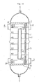
- a plurality of reaction tubes (heat transfer tubes) 1 packed with catalyst and disposed in parallel to one another are fixed by upper and lower header plates 2.
- Heat medium serving as shell side fluid is introduced into a reactor shell 11 through an inlet nozzle 3 at the lower portion of the reactor shell 11, and after reaction heat has been recovered, the heat medium is discharged through an outlet nozzle 4 at the upper portion of the reactor shell 11.
- a plurality of baffle plates 5 are disposed within the reactor shell 11. The arrangement is such that raw material gas formed by mixing heated fluid propylene with air may flow into the reaction tubes 1 from the above through a nozzle 6, and after acrylic acid has been produced in the tubes 1 it is discharged through a nozzle 7.
- baffle plates or rods as shown in Figs. 15, 16 and 17 were disposed.
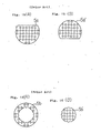
- Fig. 15 shows a most generally used baffle plate of partly broken circular shape.
- Partly broken circular plates 5a and 5a′ as shown in Figs 15(A) and 15(B), respectively, are disposed alternately in the direction of flow of the shell side fluid.
- Fig. 16 shows another example of the baffle plates, and in this example an annular (doughnut-shaped) plates 5b and circular plates 5b′ are alternately disposed along the flow direction of the shell side fluid, that is, circular-/annular-shaped baffle plates are used.
- this type of baffle plates although pressure loss is reduced as compared to the above-described baffle plates of partly broken circular shape in Fig. 15, as the above-mentioned problem (2) is not yet resolved, distribution is produced in the shell side heat transfer coefficient, and so, this construction was unfavorable, for instance, for a reactor packed with catalyst having high temperature-dependent characteristic.
- the present invention has been worked out in order to resolve the above-mentioned problems inherent to a multi-tube type heat transfer apparatus in the prior art, and it is one object of the present invention to provide a multi-tube type heat transfer apparatus that is especially effective as a large-capacity reactor apparatus or heat-exchanger apparatus which is required to have low pressure loss or uniform heat transfer performance.
- a multi-tube type heat transfer apparatus comprising a shell surrounding a plurality of heat transfer tubes, a plurality of baffle plates disposed at intervals within the shell, each of the baffle plates being provided with a plurality of holes having a larger diameter than the outer diameter of the heat transfer tube, the heat transfer tubes extending through the respective holes in the baffle plates, and a flow passageway of fluid on the side of the shell consisting of annular spaces formed between the outer circumferences of the heat transfer tubes and the inner circumferences of the holes in the baffle plates.
- the first-featured multi-tube type heat transfer apparatus wherein the inner diameters of the plurality of holes in the respective baffle plates are distributed, and thereby the cross-section areas of the flow passageways of the fluid on the side of the shell between the outer circumferences of the heat transfer tubes and the inner circumferences of the holes in the baffle plates are distributed.
- thermoelectric transfer apparatus wherein heat transfer tubes provided with fins extend through the respective ones of the plurality of holes in the baffle plates.
- the last-featured multi-tube type heat transfer apparatus wherein the fins of the heat transfer tubes are held in contact with the inner circumferential wall of the holes in the baffle plates to support the heat transfer tubes.
- the above-featured multi-tube type heat transfer apparatus which apparatus further comprises a cylindrical body having its opposite ends closed, and disposed at the center of the shell in parallel to the heat transfer tubes.
- the cross-section areas of the same flow passageways can be chosen at an appropriate magnitude, thereby pressure loss is reduced, and heat transfer performance can be enhanced.
- the flow rate in the radial directions can be set at an appropriate value by appropriately selecting the distribution of the hole diameters. Accordingly, the flow rate ratio of the flow in the radial direction of the heat transfer apparatus to the flow in the axial direction perpendicular to the baffle plates can be arbitrarily set, and heat transfer performance can be enhanced within an allowable limit of the pressure loss.
- the shell side fluid is made to flow in the radial directions in the heat transfer tube group in the introducing section or in the lead-out section, thereby pressure loss produced at the central portion is compensated, and flow rate distribution of the flow in the axial direction can be made uniform.
- the cross-section areas of the same annular passageways can be made to have an appropriate magnitude, thereby pressure loss of the shell side fluid is reduced and heat transfer performance is enhanced, and furthermore, owing to the fins provided on the heat transfer tubes, higher and uniform heat transfer performance can be obtained.
- the heat transfer apparatus further comprises a cylindrical body having its opposite end closed, and disposed at the center of the shell in parallel to the heat transfer tubes, the following advantages are obtained:
- baffle plates of #1 - #7 are provided at intervals in the direction of flow of the shell side fluid from the below to the above within a reactor shell 11 as shown in Fig. 2, and the outer circumferences of the respective baffle plates are fixedly secured to the whole inner circumference of the outer wall of the reactor shell 11.
- annular dispersing tubes 8 having a plurality of slit holes 8′ and surrounding the reactor shell 11.
- the heat transfer tubes 1 extend through the respective holes, and annular space portions formed between the inner circumferences of these holes and the outer circumferences of the heat transfer tubes 1 are used as flow passageways 10 of the shell side fluid. It is to be noted that arrows in this figure indicate directions of flow of the shell side fluid.
- This preferred embodiment has been designed for that purpose, and as will be described in the following, the above-described first preferred embodiment has been modified in such manner that the cross-section areas of the annular flow passageways in the respective baffle plates are distributed to produce radial flows.
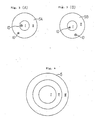
- the hole diameters in a region I at the central portion of the baffle plate 5A are chosen large so that cross-section areas of annular flow passageways 10 around the heat transfer tubes disposed in the region I at the central portion delimited by a circumference may become large, but the hole diameters in a region II at the peripheral portion of the baffle plate 5A are chosen small so that cross-section areas of annular flow passageways 10 around the heat transfer tubes disposed in the region II at the ring-shaped peripheral portion may become small.
- the hole diameters in the region I at the central portion are chosen small so that cross-section areas of annular flow passageways 10 around the heat transfer tubes disposed in the region I at the central portion may become small, but the hole diameters in the region II at the peripheral portion are chosen large so that cross-section areas of annular flow passageways 10 around the heat transfer tubes disposed in the region II at the peripheral portion may become large.
- the baffle plate 5 in the introducing section indicated by #1 in Fig. 2 and the baffle plate 5 in the lead-out section indicated by #7 are formed in the following structure. That is, as shown in Fig. 4, the baffle plates 5 are divided by concentric circles into a central portion of a shell (region I), a peripheral portion (region III) and an intermediate portion (region II) therebetween, the cross-section areas of the annular flow passageways around the respective heat transfer tubes in the central portion (region I) are made large, and the cross-section areas of the annular flow passageways are successively reduced in the intermediate portion (region II) and in the peripheral portion (region III).
- a flow rate in the axial direction of the shell in the central portion (region I) may not decrease due to pressure loss generated by the shell side fluid flowing across the heat transfer tube group in the radial direction
- flow passageway cross-section areas in the central portion (region I) are enlarged, and the flow passageway cross-section areas are successively reduced towards the outside of the reactor shell, thereby pressure loss caused by radial flow can be compensated, and distribution of flow rates in the axial direction of the reactor shell can be made uniform.
- the flow passageway cross-section areas in the baffle plates other than the #1 baffle plate in the introducing portion and the #7 baffle plate in the lead-out portion could be appropriately varied along the radial direction.
- This example of application employs a reactor apparatus as shown in Fig. 2.
- Process fluid is introduced through an inlet nozzle 6 into a reactor apparatus, then it performs predetermined reaction within 11000 catalyst-packed reactor tubes 1 each having an outer diameter of 26 mm and a tube length of 12000 mm, and reaction heat generated at that time is effectively recovered by heat medium forming shell side fluid which is flowing outside of the tubes. And the process fluid after reaction is discharged through an outlet nozzle 7.
- heat medium consisting of nitrate group molten salt flowing at a flow rate of 10000 m3/h flows from an inlet nozzle 3 through an annular dispersing tube having slit holes and is introduced from an outer circumferential portion of a reactor shell 11 having an inner diameter of 3700 mm into the reactor shell.
- a baffle plate consisting of a central portion (region I), an intermediate portion (region II) and a peripheral portion (region III) according to the above-described third preferred embodiment, is employed.
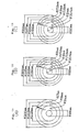
- the dimensions of the above-described respective portions are as shown in Fig. 5(A), the dimensions of the diameters of holes in the respective portions of the baffle plate are 31 mm, 28 mm and 27 mm as indicated at A, B and C, respectively, in the same figure, the diameters of holes are set at successively reduced values from the central portion via the intermediate portion up to the peripheral portion, and accordingly the cross-section areas of the annular flow passageways are also successively reduced.
- the heat medium introduced into the reactor shell is, at first, rectified into axial flow that is nearly uniform in the radial direction by the same baffle plate #1.
- This baffle plate #2 is a baffle plate constructed according to the aforementioned second preferred embodiment, that is, in the region I and the region III in the same figure, holes having small diameters for making flow passageway cross-section areas small are provided, whereas in the region II and the region IV, holes having large diameters for making flow passageway cross-section areas large are provided.
- the dimensions of the respective regions I - IV and the hole diameters A - D in these regions are respectively as indicated in Fig. 5(B).
- This baffle plate #3 is also a baffle plate according to the above-described second preferred embodiment, and as shown in the same figure, in the region I and the region III, holes having large diameters for making flow passageway cross-section areas large are provided, whereas in the region II and the region IV, holes having small diameters for making flow passageway cross-section areas small are provided.
- the dimensions of the respective regions and the hole diameters A - D are as indicated in the same figure.
- the heat medium having passed through the baffle plate #6 has its flow in the axial direction of the reactor shell made uniform along the radial direction by passing through the baffle plate #7 at the uppermost level having a similar structure to the above-described baffle plate #1, and thereafter it passes through an annular dispersing tube having similar slit holes to that on the side of the inlet nozzle 3, and is led out through an outlet nozzle 4 to the outside of the reactor apparatus.
- This preferred embodiment is an embodiment applied to a reactor of the type shown in Fig. 14, in which improvements have been made in the portions described in the following.
- Figs. 8 and 9 component parts equivalent to those in the reactor shown in Fig. 14 are given like reference numerals, and further explanation thereof will be omitted.
- a reactor shell 11 is provided with seven baffle plates 5 of #1 - #7 at intervals in the direction of the shell side fluid from the below to the above, and the outer circumferences of the respective baffle plates are fixedly secured to the whole inner circumferential surfaces of the outer wall of the reactor shell 11.
- annular dispersing pipes 8 each having a plurality of slit holes 8′ and surrounding the reactor shell 11.
- baffle plates 5 in the respective baffle plates 5 are formed a plurality of holes having sufficiently larger diameters than the diameters of the heat transfer tubes (reactor tubes) 1, and the annular space portions formed between the inner circumferences of these holes and the outer circumferences of the heat transfer tubes 1 are used as flow passageways 10 of the shell side fluid.
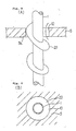
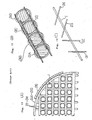
- two fins 20 surrounding the heat transfer tube 1 obliquely to the axial direction of the heat transfer tube 1, that is, in a spiral manner are mounted to the outer circumference of the same heat transfer tube 1, the outer diameters of these fins 20 are chosen equal to the inner diameter of the hole in the baffle plate 5, and one of the fins 20 is adapted to support the heat transfer tube 1 as held in contact with the inner wall surface 5a of the hole.
- reference numeral 9 designates rectifier plates, and an arrow in Fig. 8(A) indicates the direction of flow of the shell side fluid.
- process fluid is introduced through an inlet nozzle 6 into the reactor and performs predetermined reaction within the heat transfer tubes 1 packed with catalyst, then reaction heat generated at that time is recovered by heat medium which is flowing along the outside of the heat transfer tubes 1 with an extremely high heat transfer coefficient owing to a fin effect, and the process fluid after reaction is discharged through an outlet nozzle 7.
- heat medium consisting of nitrate group molten salt enters from an inlet nozzle 3, then passes through an annular dispersing tube 8 having slit holes, and is introduced from the outer circumferential portion of the reactor shell into the same reactor shell, and it flows from the below to the above through the annular flow passageways 10 formed by the holes in the baffle plates 5 serving also as tube supporting plates and the heat transfer tubes 1 having the fins 20 serving also as a supporting device.
- the cross-section areas of the annular flow passageways 10 can be set at an appropriate dimension, and thereby pressure loss of the shell side fluid can be reduced.
- the shell side fluid can flow within the shell nearly in parallel to the heat transfer tubes, hence pressure loss generated by radial flow is not present, and also by the effects of the fins 20 it is possible to maintain high heat transfer performance that is uniform along the radial direction and along the axial direction.
- the heat transfer tube 1 is provided with fins 20 which surround the heat transfer tube in a spiral manner in the above-described fourth preferred embodiment, the fins should not be limited to such type, but any other type of fins can be employed so long as they allow the shell side fluid to flow through the annular flow passageway 10.
- process fluid is introduced into a reactor shell 11 through an inlet nozzle 6 at the top and performs predetermined reaction within a group of catalyst-packed heat transfer tubes (reactor tubes 1) consisting of about 11000 tubes having an outer diameter of 26 mm and a tube length of 12000 mm and disposed in parallel to one another, and reaction heat generated at that time is effectively recovered by heat medium consisting of the shell side fluid flowing outside of the tubes. And the process fluid after reaction is discharged through an outlet nozzle 7 at the bottom.
- reactor tubes 1 catalyst-packed heat transfer tubes
- the shell side fluid (heat medium) consisting of nitrate group molten salt flowing at a rate of 10000 m3/h flows from an inlet nozzle 3 provided at the lower portion of the reactor shell 11 through an annular dispersing tube 8 having slit holes 8′, and is introduced into the reactor shell 11 having an inner diameter of 3700 mm from its outer circumferential portion.
- dummy tubes 9 In the central portion of the reactor shell 11 are disposed a plurality of dummy tubes 9 having the same outer diameter as the heat transfer tubes 1 and arrayed in parallel to the heat transfer tubes 1. These dummy tubes 9 are not fixed to the upper nor lower header plate 2, their upper and lower ends are located a certain distance apart from the header plates 2, their upper ends are located between the baffle plates 5 of #6 and #7, their lower ends are located between the baffle plates 5 of #1 and #2, and also they are supported by the baffle plates 5 of #2 to #6. At the both lower and upper ends of the dummy tubes 9 are respectively provided blind plates 12 and 12′.
- baffle plate #1 As the lowermost level baffle plate #1 (See Fig. 11), a baffle plate consisting of a central portion (region I), an intermediate portion (region II) and a peripheral portion (region III) is employed, and at the center of the central portion (region I) is formed a hole of 300 mm in diameter.
- the dimensions of the respective portions are as indicated in Fig. 11(A), the dimensions of the diameters of the holes in the respective regions of the baffle plate through which the heat transfer tubes 1 extend are 31 mm, 28 mm and 27 mm, respectively, as shown at A, B and C in the same figure, the diameters of the holes are chosen successively smaller from the central portion, through the intermediate portion up to the peripheral portion, and accordingly, the cross-section areas of the annular flow passageways formed between the holes of the baffle plates and the heat transfer tubes 1 are also reduced successively.
- a plurality of dummy tubes 9 as described above at the same pitch as the other heat transfer tubes 1.
- the shell side fluid which has risen through this hole is dispersed in the horizontal directions by the blind plate 12 of the dummy tubes 9 and mixed with shell side fluid which has passed through the central portion (region I) of the baffle plate #1, and then it rises further.
- the amount of the fluid entering into the central portion becomes large, and moreover, in the central portion since there exists a hole of 300 mm in diameter and heat transfer tubes are not present, a temperature difference in the radial direction of the reactor shell or a width of temperature rise in the inlet region can be suppressed.
- the shell side fluid flows from the below to the above within the reactor shell, and moves towards the baffle plate #2 as shown in Fig. 11(B).
- the baffle plate #2 in the region I and the region III shown in this figure, holes having small diameters for reducing cross-section areas of flow passageways are formed, while in the region II and the region IV holes having large diameters for enlarging cross-section areas of flow passageways are formed.
- a partial region I′ of 300 mm in diameter at the center of the central portion (region I) are formed a plurality of small holes through which the above-described respective dummy tubes 9 extend.
- the shell side fluid flows through the interstices of the dummy tubes 9 in nearly parallel flow, and the flow rate in the axial direction is nearly equal to that in the region where the heat transfer tubes 1 packed with catalyst exist.
- stagnation of the shell side fluid is reduced, and a heat transfer coefficient around the heat transfer tubes surrounding the region where the heat transfer tubes were removed, also becomes large.
- the dummy tubes 9 extend through the holes of ⁇ 26.4 mm in the baffle plate, though only a little, the shell side fluid can pass through the interstices between the holes in the baffle plate and the dummy tubes, and so, stagnation of the shell side fluid under the baffle plate 5 of #2 can be prevented.
- the shell side fluid having passed through the baffle plate 5 of #2 subsequently moves towards the baffle plate 5 of #3 shown in Fig. 11(C).
- this baffle plate #3 holes having large diameters for enlarging the cross-section areas of flow passageways are formed in the region I and in the region III, but in the region II and in the region IV, holes having small diameters for reducing the cross-section areas of flow passageways are formed.
- the dimensions of the respective regions I - IV and the diameters A - D of the holes in the respective regions are as indicated in Fig. 11(C).
- the shell side fluid having passed through the baffle plate #6 will then pass through the uppermost level baffle plate #7 having a similar structure to the above-described baffle plate #1.
- the top ends of the dummy tube 9 are disposed apart from the upper header plate 2′ and positioned under the baffle plate #7, and in the central portion of the baffle plate #7 is also formed a hole of ⁇ 300 mm.
- the shell side fluid passes through an annular dispersing tube 8 having slit holes 8′ which is similar to that on the side of the inlet nozzle 3, and is led out from an outlet nozzle 4 to the outside of the reactor apparatus.
- dummy tubes are provided at the central portion, they are not fixed to the upper and lower header plates, but they are disposed an arbitrary distance apart from the header plates, it has become possible to suppress temperature difference of the shell side fluid in the radial direction.
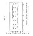
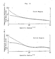
- Fig. 12 are shown temperature distribution in the radial direction (dotted lines) in the inlet region and outlet region of a multi-tube type catalytic reactor apparatus which is one example of application of the above-described second preferred embodiment shown in Fig. 5 and similar temperature distribution (solid lines) according to this preferred embodiment.
- Fig. 12 according to this preferred embodiment, as compared to the apparatus shown in Fig. 6, in the inlet region a temperature difference was improved from about 1.7°C to about 0.8°C, and in the outlet region it was improved from about 1.8°C to about 0.8°C.
- FIG. 13 A sixth preferred embodiment of the present invention is illustrated in Fig. 13.
- a cylinder 9′ having its lower and upper ends closed by blind plates 12 and 12′, respectively, is disposed.
- the cylinder 9′ is supported by the baffle plates 5 of #2 to #6.
- the used baffle plates are almost similar to those shown in Fig. 11. However, in the region I′ of the baffle plates of #2 to #6, a large number of small-diameter holes are not formed but a single hole having a large diameter is formed.
- the opposite ends of the cylindrical body could be fixed by the header plates, or modification could be made such that one end is fixed to a header plate and the other portions are supported by the baffle plates, and the other end may be positioned apart from a header plate.
- support of the cylindrical body could be done by a tube supporting plate fixed to the reactor shell without using the baffle plates.
- annular flow passageways of shell side fluid are provided between holes in baffle plates and heat transfer tubes extending through the holes, pressure loss of the shell side fluid is reduced, and good heat transfer performance can be obtained.
- a flow rate in the radial direction that is appropriate with respect to a flow rate in the axial direction is given to the flow of the shell side fluid within a heat transfer apparatus, thereby heat transfer performance can be enhanced within an allowable limit of pressure loss, and further, flow rate distribution in the axial flow can be made uniform.
- the heat transfer tubes can be supported by cooperation of the fins and the circumferential wall surfaces of the holes in the baffle paltes, and therefore, the heat transfer tubes can be supported without necessitating any special supporting device.
- a cylindrical body having its opposite ends closed in the central portion of a multi-tube type heat transfer apparatus, in which annular flow passageways of shell side fluid are provided between holes in baffle plates and heat transfer tubes extending therethrough, stagnation of the shell side fluid that is liable to arise in the central portion of the apparatus can be prevented, and temperature difference in the radial direction of the shell side fluid can be suppressed.
- the end of the cylindrical body is disposed an arbitrary distance apart from a header plate, a flow rate of the shell side fluid flowing from the inlet of the shell towards the center is increased, and thereby temperature difference of the shell side fluid in the radial direction can be suppressed further effectively.
Landscapes
- Engineering & Computer Science (AREA)
- Chemical & Material Sciences (AREA)
- Physics & Mathematics (AREA)
- Thermal Sciences (AREA)
- Mechanical Engineering (AREA)
- General Engineering & Computer Science (AREA)
- Organic Chemistry (AREA)
- Chemical Kinetics & Catalysis (AREA)
- Heat-Exchange Devices With Radiators And Conduit Assemblies (AREA)
- Devices And Processes Conducted In The Presence Of Fluids And Solid Particles (AREA)
Applications Claiming Priority (6)
| Application Number | Priority Date | Filing Date | Title |
|---|---|---|---|
| JP29951/89 | 1989-02-10 | ||
| JP2995189A JPH02213697A (ja) | 1989-02-10 | 1989-02-10 | フィン付き多管式伝熱装置 |
| JP29950/89 | 1989-02-10 | ||
| JP1029950A JPH0827154B2 (ja) | 1989-02-10 | 1989-02-10 | 多管式伝熱装置 |
| JP29497189A JPH03156289A (ja) | 1989-11-15 | 1989-11-15 | 多管式伝熱装置 |
| JP294971/89 | 1989-11-15 |
Publications (4)
| Publication Number | Publication Date |
|---|---|
| EP0382098A2 true EP0382098A2 (fr) | 1990-08-16 |
| EP0382098A3 EP0382098A3 (en) | 1990-11-07 |
| EP0382098B1 EP0382098B1 (fr) | 1993-09-22 |
| EP0382098B2 EP0382098B2 (fr) | 1997-01-02 |
Family
ID=27286780
Family Applications (1)
| Application Number | Title | Priority Date | Filing Date |
|---|---|---|---|
| EP90102020A Expired - Lifetime EP0382098B2 (fr) | 1989-02-10 | 1990-02-01 | Dispositif de transfert de chaleur du type à multitube |
Country Status (4)
| Country | Link |
|---|---|
| US (1) | US4991648A (fr) |
| EP (1) | EP0382098B2 (fr) |
| CA (1) | CA2009624C (fr) |
| DE (1) | DE69003404T3 (fr) |
Cited By (8)
| Publication number | Priority date | Publication date | Assignee | Title |
|---|---|---|---|---|
| EP0644394A1 (fr) * | 1993-09-21 | 1995-03-22 | Proizvodstvennoe Obiedinenie "Chernovitsky Mashinostroitelny Zavod" | Echangeur de chaleur |
| WO2004052524A1 (fr) * | 2002-12-12 | 2004-06-24 | Man Dwe Gmbh | Reacteur tubulaire a enveloppe pour des reactions catalytiques en phase gazeuse |
| EP1600209A1 (fr) * | 2004-05-29 | 2005-11-30 | Haldor Topsoe A/S | Procédé et réacteur avec échange de chaleur |
| EP1425539A4 (fr) * | 2001-09-15 | 2006-05-24 | Precision Combustion Inc | Chicane pour reacteurs a canaux a ecoulement unique |
| DE102007013362A1 (de) | 2007-03-16 | 2008-09-18 | Bayer Cropscience Ag | Penetrationsförderer für herbizide Wirkstoffe |
| EP1813346A4 (fr) * | 2004-09-27 | 2008-10-22 | Sumitomo Chemical Co | Appareil de réaction multitubulaire pour réaction en phase gazeuse par contact |
| DE102010048405A1 (de) | 2010-10-15 | 2011-05-19 | Basf Se | Verfahren zum Langzeitbetrieb einer heterogen katalysierten partiellen Gasphasenoxidation von Proben zu Acrolein |
| DE102010014643A1 (de) | 2010-04-12 | 2011-10-13 | Man Diesel & Turbo Se | Rohrbündelreaktor |
Families Citing this family (14)
| Publication number | Priority date | Publication date | Assignee | Title |
|---|---|---|---|---|
| US5203405A (en) * | 1992-02-03 | 1993-04-20 | Phillips Petroleum Company | Two pass shell and tube heat exchanger with return annular distributor |
| US5477846A (en) * | 1994-08-17 | 1995-12-26 | Cameron; Gordon M. | Furnace-heat exchanger preheating system |
| US6089312A (en) * | 1998-06-05 | 2000-07-18 | Engineers And Fabricators Co. | Vertical falling film shell and tube heat exchanger |
| JP3961254B2 (ja) * | 2001-09-28 | 2007-08-22 | 株式会社日本触媒 | 多管式熱交換器および該熱交換器を用いる(メタ)アクリル酸の製造方法 |
| DE10333463C5 (de) * | 2003-07-22 | 2014-04-24 | Alstom Technology Ltd. | Rohrbündelwärmetauscher |
| CN1299095C (zh) * | 2004-10-20 | 2007-02-07 | 辽宁石油化工大学 | 蛛网状折流栅换热器 |
| DE102005001952A1 (de) * | 2005-01-14 | 2006-07-27 | Man Dwe Gmbh | Rohrbündelreaktor zur Durchführung exothermer oder endothermer Gasphasenreaktionen |
| DE102007034690B4 (de) * | 2007-07-12 | 2009-06-10 | Erwin Ott | Verdampfer und Füllplatte hierfür |
| WO2013049219A1 (fr) | 2011-09-26 | 2013-04-04 | Ingersoll Rand Company | Évaporateur de réfrigérant |
| KR101422347B1 (ko) * | 2012-10-23 | 2014-07-22 | (주)귀뚜라미 | 더미 관을 갖는 응축 열교환기 |
| DE102012222560A1 (de) * | 2012-12-07 | 2014-06-12 | Bayerische Motoren Werke Aktiengesellschaft | Reaktor zur Freisetzung von Wasserstoff |
| US10907822B2 (en) * | 2015-02-12 | 2021-02-02 | Anhui Conch Kawasaki Engineering Company Limited | Waste heat boiler |
| CN112108097B (zh) * | 2020-09-10 | 2022-05-24 | 军事科学院系统工程研究院军需工程技术研究所 | 一种新型管式增粘设备 |
| JP7738496B2 (ja) * | 2022-02-04 | 2025-09-12 | 三菱重工業株式会社 | 熱交換器 |
Family Cites Families (10)
| Publication number | Priority date | Publication date | Assignee | Title |
|---|---|---|---|---|
| US827479A (en) * | 1905-12-26 | 1906-07-31 | Harry W Hand | Condenser. |
| FR514024A (fr) * | 1919-10-18 | 1921-03-01 | Wladimir Witkowicz | Appareil échangeur de chaleur |
| US2662911A (en) * | 1948-10-01 | 1953-12-15 | Metallgesellschaft Ag | Temperature control in the catalytic hydrogenation of carbon monoxide |
| CH493811A (de) * | 1967-09-06 | 1970-07-15 | Basf Ag | Wärmetauschvorrichtung |
| DE2657666A1 (de) * | 1976-12-20 | 1977-12-22 | Richard Vad | Waermetauschereinsatz |
| AU529228B2 (en) * | 1977-07-13 | 1983-06-02 | Nippon Shokubai Kagaku Kogyo Co. Ltd. | Catalytic vapour phase oxidation |
| GB2081868B (en) * | 1980-08-07 | 1984-04-26 | Applegate G | Improvements in or relating to heat exchangers and/or silencers |
| US4749031A (en) * | 1982-07-29 | 1988-06-07 | Nisshin Chemical Industry Co., Ltd. | Heat exchanging device having baffles and fluorocarbon tubes |
| SU1198370A1 (ru) * | 1984-01-13 | 1985-12-15 | Проектно-Конструкторский Технологический Экспериментальный Институт Машиностроения | Поперечна направл юща перегородка кожухотрубного теплообменника |
| US4709756A (en) * | 1984-11-13 | 1987-12-01 | Westinghouse Electric Corp. | Steam generator tube support |
-
1990
- 1990-02-01 DE DE69003404T patent/DE69003404T3/de not_active Expired - Fee Related
- 1990-02-01 EP EP90102020A patent/EP0382098B2/fr not_active Expired - Lifetime
- 1990-02-07 US US07/476,548 patent/US4991648A/en not_active Expired - Lifetime
- 1990-02-08 CA CA002009624A patent/CA2009624C/fr not_active Expired - Fee Related
Cited By (12)
| Publication number | Priority date | Publication date | Assignee | Title |
|---|---|---|---|---|
| EP0644394A1 (fr) * | 1993-09-21 | 1995-03-22 | Proizvodstvennoe Obiedinenie "Chernovitsky Mashinostroitelny Zavod" | Echangeur de chaleur |
| EP1425539A4 (fr) * | 2001-09-15 | 2006-05-24 | Precision Combustion Inc | Chicane pour reacteurs a canaux a ecoulement unique |
| WO2004052524A1 (fr) * | 2002-12-12 | 2004-06-24 | Man Dwe Gmbh | Reacteur tubulaire a enveloppe pour des reactions catalytiques en phase gazeuse |
| EP1600209A1 (fr) * | 2004-05-29 | 2005-11-30 | Haldor Topsoe A/S | Procédé et réacteur avec échange de chaleur |
| US7780926B2 (en) | 2004-05-29 | 2010-08-24 | Haldor Topsøe A/S | Heat exchange process and reactor |
| EP1813346A4 (fr) * | 2004-09-27 | 2008-10-22 | Sumitomo Chemical Co | Appareil de réaction multitubulaire pour réaction en phase gazeuse par contact |
| US7771674B2 (en) | 2004-09-27 | 2010-08-10 | Sumitomo Chemical Company, Limited | Multitubular reaction apparatus for contact gas-phase reaction |
| DE102007013362A1 (de) | 2007-03-16 | 2008-09-18 | Bayer Cropscience Ag | Penetrationsförderer für herbizide Wirkstoffe |
| DE102010014643A1 (de) | 2010-04-12 | 2011-10-13 | Man Diesel & Turbo Se | Rohrbündelreaktor |
| DE102010048405A1 (de) | 2010-10-15 | 2011-05-19 | Basf Se | Verfahren zum Langzeitbetrieb einer heterogen katalysierten partiellen Gasphasenoxidation von Proben zu Acrolein |
| WO2012049246A2 (fr) | 2010-10-15 | 2012-04-19 | Basf Se | Procédé pour réaliser, sur une longue durée, l'oxydation en phase gazeuse partielle à catalyse hétérogène de propène en acroléine |
| US8618336B2 (en) | 2010-10-15 | 2013-12-31 | Basf Se | Process for long-term operation of a heterogeneously catalyzed partial gas phase oxidation of propene to acrolein |
Also Published As
| Publication number | Publication date |
|---|---|
| EP0382098B1 (fr) | 1993-09-22 |
| CA2009624A1 (fr) | 1990-08-10 |
| CA2009624C (fr) | 1993-08-31 |
| EP0382098B2 (fr) | 1997-01-02 |
| EP0382098A3 (en) | 1990-11-07 |
| DE69003404T3 (de) | 1997-05-15 |
| US4991648A (en) | 1991-02-12 |
| DE69003404D1 (de) | 1993-10-28 |
| DE69003404T2 (de) | 1994-01-13 |
Similar Documents
| Publication | Publication Date | Title |
|---|---|---|
| EP0382098B1 (fr) | Dispositif de transfert de chaleur du type à multitube | |
| RU2279307C2 (ru) | Псевдоизотермический каталитический реактор и блочный теплообменник для проведения экзотермических и эндотермических химических реакций | |
| US7022294B2 (en) | Compact reactor | |
| US5161605A (en) | Tubular reactor and method | |
| US7767601B2 (en) | Shell-type reactor with radial baffles | |
| US4060127A (en) | Shell-and-tube heat exchanger | |
| US7326811B2 (en) | Method for production of (meth)acrylic acid by use of a shell-and-tube heat exchanger | |
| JP2006510471A (ja) | 触媒気相反応のためのジャケット管反応装置 | |
| JP2004083430A (ja) | 多管式反応器を用いた気相接触酸化方法 | |
| RU2295383C2 (ru) | Способ каталитического окисления в паровой фазе | |
| EP2244821B1 (fr) | Réacteur chimique isotherme avec échangeur thermique de plaque | |
| WO2003031050A1 (fr) | Reacteur echangeur de chaleur | |
| KR101278115B1 (ko) | 촉매 변환 반응을 위한 반응기 | |
| JP4422940B2 (ja) | 熱交換器付き小型反応器 | |
| JPH0827154B2 (ja) | 多管式伝熱装置 | |
| CN223263798U (zh) | 列管式反应器的壳程结构 | |
| JPH03156289A (ja) | 多管式伝熱装置 | |
| CN113624039A (zh) | 一种圆弧引流板弧度变化的管壳式换热器 | |
| CN113624038A (zh) | 一种管壳式换热器 | |
| JPH02213697A (ja) | フィン付き多管式伝熱装置 | |
| US20240293787A1 (en) | Catalytic heat exchange reactor with helical flow | |
| RU2192593C1 (ru) | Спиральный теплообменник | |
| CN113686177A (zh) | 一种直线均温导流的管壳式换热器 | |
| JPS63315893A (ja) | 多管式熱交換器 | |
| CN107835713A (zh) | 催化反应器 |
Legal Events
| Date | Code | Title | Description |
|---|---|---|---|
| PUAI | Public reference made under article 153(3) epc to a published international application that has entered the european phase |
Free format text: ORIGINAL CODE: 0009012 |
|
| 17P | Request for examination filed |
Effective date: 19900226 |
|
| AK | Designated contracting states |
Kind code of ref document: A2 Designated state(s): DE GB |
|
| PUAL | Search report despatched |
Free format text: ORIGINAL CODE: 0009013 |
|
| AK | Designated contracting states |
Kind code of ref document: A3 Designated state(s): DE GB |
|
| 17Q | First examination report despatched |
Effective date: 19910806 |
|
| GRAA | (expected) grant |
Free format text: ORIGINAL CODE: 0009210 |
|
| AK | Designated contracting states |
Kind code of ref document: B1 Designated state(s): DE GB |
|
| REF | Corresponds to: |
Ref document number: 69003404 Country of ref document: DE Date of ref document: 19931028 |
|
| PLBI | Opposition filed |
Free format text: ORIGINAL CODE: 0009260 |
|
| 26 | Opposition filed |
Opponent name: DEGGENDORFER WERFT UND EISENBAU GESELLSCHAFT M.B.H Effective date: 19940317 |
|
| PLAW | Interlocutory decision in opposition |
Free format text: ORIGINAL CODE: EPIDOS IDOP |
|
| PLAW | Interlocutory decision in opposition |
Free format text: ORIGINAL CODE: EPIDOS IDOP |
|
| PUAH | Patent maintained in amended form |
Free format text: ORIGINAL CODE: 0009272 |
|
| STAA | Information on the status of an ep patent application or granted ep patent |
Free format text: STATUS: PATENT MAINTAINED AS AMENDED |
|
| 27A | Patent maintained in amended form |
Effective date: 19970102 |
|
| AK | Designated contracting states |
Kind code of ref document: B2 Designated state(s): DE GB |
|
| REG | Reference to a national code |
Ref country code: GB Ref legal event code: IF02 |
|
| PGFP | Annual fee paid to national office [announced via postgrant information from national office to epo] |
Ref country code: GB Payment date: 20030129 Year of fee payment: 14 |
|
| PGFP | Annual fee paid to national office [announced via postgrant information from national office to epo] |
Ref country code: DE Payment date: 20030213 Year of fee payment: 14 |
|
| PG25 | Lapsed in a contracting state [announced via postgrant information from national office to epo] |
Ref country code: GB Free format text: LAPSE BECAUSE OF NON-PAYMENT OF DUE FEES Effective date: 20040201 |
|
| PG25 | Lapsed in a contracting state [announced via postgrant information from national office to epo] |
Ref country code: DE Free format text: LAPSE BECAUSE OF NON-PAYMENT OF DUE FEES Effective date: 20040901 |
|
| GBPC | Gb: european patent ceased through non-payment of renewal fee |
Effective date: 20040201 |