EP0382374B1 - Koaxialleiter-Abschlussteckersystem - Google Patents
Koaxialleiter-Abschlussteckersystem Download PDFInfo
- Publication number
- EP0382374B1 EP0382374B1 EP90300771A EP90300771A EP0382374B1 EP 0382374 B1 EP0382374 B1 EP 0382374B1 EP 90300771 A EP90300771 A EP 90300771A EP 90300771 A EP90300771 A EP 90300771A EP 0382374 B1 EP0382374 B1 EP 0382374B1
- Authority
- EP
- European Patent Office
- Prior art keywords
- sleeve
- termination device
- outer conductor
- termination
- conductor
- Prior art date
- Legal status (The legal status is an assumption and is not a legal conclusion. Google has not performed a legal analysis and makes no representation as to the accuracy of the status listed.)
- Expired - Lifetime
Links
- 239000004020 conductor Substances 0.000 title claims description 65
- 230000008878 coupling Effects 0.000 claims description 16
- 238000010168 coupling process Methods 0.000 claims description 16
- 238000005859 coupling reaction Methods 0.000 claims description 16
- 239000012212 insulator Substances 0.000 claims description 8
- 238000005476 soldering Methods 0.000 description 9
- 229910000679 solder Inorganic materials 0.000 description 6
- XEEYBQQBJWHFJM-UHFFFAOYSA-N Iron Chemical compound [Fe] XEEYBQQBJWHFJM-UHFFFAOYSA-N 0.000 description 4
- 238000009413 insulation Methods 0.000 description 2
- 229910052742 iron Inorganic materials 0.000 description 2
- 230000004907 flux Effects 0.000 description 1
- 239000002184 metal Substances 0.000 description 1
- 229910052751 metal Inorganic materials 0.000 description 1
Images

Classifications
-
- H—ELECTRICITY
- H01—ELECTRIC ELEMENTS
- H01R—ELECTRICALLY-CONDUCTIVE CONNECTIONS; STRUCTURAL ASSOCIATIONS OF A PLURALITY OF MUTUALLY-INSULATED ELECTRICAL CONNECTING ELEMENTS; COUPLING DEVICES; CURRENT COLLECTORS
- H01R9/00—Structural associations of a plurality of mutually-insulated electrical connecting elements, e.g. terminal strips or terminal blocks; Terminals or binding posts mounted upon a base or in a case; Bases therefor
-
- H—ELECTRICITY
- H02—GENERATION; CONVERSION OR DISTRIBUTION OF ELECTRIC POWER
- H02G—INSTALLATION OF ELECTRIC CABLES OR LINES, OR OF COMBINED OPTICAL AND ELECTRIC CABLES OR LINES
- H02G15/00—Cable fittings
- H02G15/02—Cable terminations
- H02G15/025—Cable terminations for coaxial cables or hollow conductors
-
- H—ELECTRICITY
- H01—ELECTRIC ELEMENTS
- H01R—ELECTRICALLY-CONDUCTIVE CONNECTIONS; STRUCTURAL ASSOCIATIONS OF A PLURALITY OF MUTUALLY-INSULATED ELECTRICAL CONNECTING ELEMENTS; COUPLING DEVICES; CURRENT COLLECTORS
- H01R13/00—Details of coupling devices of the kinds covered by groups H01R12/70 or H01R24/00 - H01R33/00
- H01R13/646—Details of coupling devices of the kinds covered by groups H01R12/70 or H01R24/00 - H01R33/00 specially adapted for high-frequency, e.g. structures providing an impedance match or phase match
-
- H—ELECTRICITY
- H01—ELECTRIC ELEMENTS
- H01R—ELECTRICALLY-CONDUCTIVE CONNECTIONS; STRUCTURAL ASSOCIATIONS OF A PLURALITY OF MUTUALLY-INSULATED ELECTRICAL CONNECTING ELEMENTS; COUPLING DEVICES; CURRENT COLLECTORS
- H01R13/00—Details of coupling devices of the kinds covered by groups H01R12/70 or H01R24/00 - H01R33/00
- H01R13/46—Bases; Cases
- H01R13/502—Bases; Cases composed of different pieces
-
- H—ELECTRICITY
- H01—ELECTRIC ELEMENTS
- H01R—ELECTRICALLY-CONDUCTIVE CONNECTIONS; STRUCTURAL ASSOCIATIONS OF A PLURALITY OF MUTUALLY-INSULATED ELECTRICAL CONNECTING ELEMENTS; COUPLING DEVICES; CURRENT COLLECTORS
- H01R24/00—Two-part coupling devices, or either of their cooperating parts, characterised by their overall structure
- H01R24/38—Two-part coupling devices, or either of their cooperating parts, characterised by their overall structure having concentrically or coaxially arranged contacts
- H01R24/40—Two-part coupling devices, or either of their cooperating parts, characterised by their overall structure having concentrically or coaxially arranged contacts specially adapted for high frequency
-
- H—ELECTRICITY
- H01—ELECTRIC ELEMENTS
- H01R—ELECTRICALLY-CONDUCTIVE CONNECTIONS; STRUCTURAL ASSOCIATIONS OF A PLURALITY OF MUTUALLY-INSULATED ELECTRICAL CONNECTING ELEMENTS; COUPLING DEVICES; CURRENT COLLECTORS
- H01R24/00—Two-part coupling devices, or either of their cooperating parts, characterised by their overall structure
- H01R24/38—Two-part coupling devices, or either of their cooperating parts, characterised by their overall structure having concentrically or coaxially arranged contacts
- H01R24/40—Two-part coupling devices, or either of their cooperating parts, characterised by their overall structure having concentrically or coaxially arranged contacts specially adapted for high frequency
- H01R24/54—Intermediate parts, e.g. adapters, splitters or elbows
- H01R24/545—Elbows
-
- H—ELECTRICITY
- H01—ELECTRIC ELEMENTS
- H01R—ELECTRICALLY-CONDUCTIVE CONNECTIONS; STRUCTURAL ASSOCIATIONS OF A PLURALITY OF MUTUALLY-INSULATED ELECTRICAL CONNECTING ELEMENTS; COUPLING DEVICES; CURRENT COLLECTORS
- H01R9/00—Structural associations of a plurality of mutually-insulated electrical connecting elements, e.g. terminal strips or terminal blocks; Terminals or binding posts mounted upon a base or in a case; Bases therefor
- H01R9/03—Connectors arranged to contact a plurality of the conductors of a multiconductor cable, e.g. tapping connections
- H01R9/05—Connectors arranged to contact a plurality of the conductors of a multiconductor cable, e.g. tapping connections for coaxial cables
- H01R9/0518—Connection to outer conductor by crimping or by crimping ferrule
-
- H—ELECTRICITY
- H02—GENERATION; CONVERSION OR DISTRIBUTION OF ELECTRIC POWER
- H02G—INSTALLATION OF ELECTRIC CABLES OR LINES, OR OF COMBINED OPTICAL AND ELECTRIC CABLES OR LINES
- H02G1/00—Methods or apparatus specially adapted for installing, maintaining, repairing or dismantling electric cables or lines
- H02G1/14—Methods or apparatus specially adapted for installing, maintaining, repairing or dismantling electric cables or lines for joining or terminating cables
-
- H—ELECTRICITY
- H01—ELECTRIC ELEMENTS
- H01R—ELECTRICALLY-CONDUCTIVE CONNECTIONS; STRUCTURAL ASSOCIATIONS OF A PLURALITY OF MUTUALLY-INSULATED ELECTRICAL CONNECTING ELEMENTS; COUPLING DEVICES; CURRENT COLLECTORS
- H01R2103/00—Two poles
-
- H—ELECTRICITY
- H01—ELECTRIC ELEMENTS
- H01R—ELECTRICALLY-CONDUCTIVE CONNECTIONS; STRUCTURAL ASSOCIATIONS OF A PLURALITY OF MUTUALLY-INSULATED ELECTRICAL CONNECTING ELEMENTS; COUPLING DEVICES; CURRENT COLLECTORS
- H01R24/00—Two-part coupling devices, or either of their cooperating parts, characterised by their overall structure
- H01R24/86—Parallel contacts arranged about a common axis
-
- H—ELECTRICITY
- H01—ELECTRIC ELEMENTS
- H01R—ELECTRICALLY-CONDUCTIVE CONNECTIONS; STRUCTURAL ASSOCIATIONS OF A PLURALITY OF MUTUALLY-INSULATED ELECTRICAL CONNECTING ELEMENTS; COUPLING DEVICES; CURRENT COLLECTORS
- H01R4/00—Electrically-conductive connections between two or more conductive members in direct contact, i.e. touching one another; Means for effecting or maintaining such contact; Electrically-conductive connections having two or more spaced connecting locations for conductors and using contact members penetrating insulation
- H01R4/02—Soldered or welded connections
- H01R4/023—Soldered or welded connections between cables or wires and terminals
-
- H—ELECTRICITY
- H01—ELECTRIC ELEMENTS
- H01R—ELECTRICALLY-CONDUCTIVE CONNECTIONS; STRUCTURAL ASSOCIATIONS OF A PLURALITY OF MUTUALLY-INSULATED ELECTRICAL CONNECTING ELEMENTS; COUPLING DEVICES; CURRENT COLLECTORS
- H01R4/00—Electrically-conductive connections between two or more conductive members in direct contact, i.e. touching one another; Means for effecting or maintaining such contact; Electrically-conductive connections having two or more spaced connecting locations for conductors and using contact members penetrating insulation
- H01R4/02—Soldered or welded connections
- H01R4/027—Soldered or welded connections comprising means for positioning or holding the parts to be soldered or welded
-
- Y—GENERAL TAGGING OF NEW TECHNOLOGICAL DEVELOPMENTS; GENERAL TAGGING OF CROSS-SECTIONAL TECHNOLOGIES SPANNING OVER SEVERAL SECTIONS OF THE IPC; TECHNICAL SUBJECTS COVERED BY FORMER USPC CROSS-REFERENCE ART COLLECTIONS [XRACs] AND DIGESTS
- Y10—TECHNICAL SUBJECTS COVERED BY FORMER USPC
- Y10S—TECHNICAL SUBJECTS COVERED BY FORMER USPC CROSS-REFERENCE ART COLLECTIONS [XRACs] AND DIGESTS
- Y10S439/00—Electrical connectors
- Y10S439/901—Connector hood or shell
- Y10S439/904—Multipart shell
-
- Y—GENERAL TAGGING OF NEW TECHNOLOGICAL DEVELOPMENTS; GENERAL TAGGING OF CROSS-SECTIONAL TECHNOLOGIES SPANNING OVER SEVERAL SECTIONS OF THE IPC; TECHNICAL SUBJECTS COVERED BY FORMER USPC CROSS-REFERENCE ART COLLECTIONS [XRACs] AND DIGESTS
- Y10—TECHNICAL SUBJECTS COVERED BY FORMER USPC
- Y10S—TECHNICAL SUBJECTS COVERED BY FORMER USPC CROSS-REFERENCE ART COLLECTIONS [XRACs] AND DIGESTS
- Y10S439/00—Electrical connectors
- Y10S439/91—Observation aide, e.g. transparent material, window in housing
-
- Y—GENERAL TAGGING OF NEW TECHNOLOGICAL DEVELOPMENTS; GENERAL TAGGING OF CROSS-SECTIONAL TECHNOLOGIES SPANNING OVER SEVERAL SECTIONS OF THE IPC; TECHNICAL SUBJECTS COVERED BY FORMER USPC CROSS-REFERENCE ART COLLECTIONS [XRACs] AND DIGESTS
- Y10—TECHNICAL SUBJECTS COVERED BY FORMER USPC
- Y10S—TECHNICAL SUBJECTS COVERED BY FORMER USPC CROSS-REFERENCE ART COLLECTIONS [XRACs] AND DIGESTS
- Y10S439/00—Electrical connectors
- Y10S439/912—Electrical connectors with testing means
Definitions
- This invention relates to a coaxial termination device having an electrically conductive substantially cylindrical outer conductor with a closed rear end having termination and access apertures, at least one inner conductor extending through an insulator in the outer conductor to the terminating aperture.
- Such a coaxial termination device may have elongated inner and outer conductors and an insulator between them, that all extend along a main axis of the device between its front and rear ends.
- the rear end of the device is devoid of insulation to provide a hollow region where the inner conductor of the device can be soldered to the inner conductor of a coaxial cable that extends perpendicular to the main axis.
- the rear end of the termination device must be closed to prevent RF (radio frequency) leakage and to seal against dirt. Thereafter, the termination device can be removably connected to coaxial apparatus by plugging into it.
- U.S. Patent 4,655,534 shows a coaxial termination device that has perpendicular outer conductors, with an access aperture in one of the outer conductors that is closed by a cover.
- the cover in this document is a loose item that can become lost when not in place to close the aperture.
- a termination device which provided a convenient access hole for soldering its inner conductor to that of a coaxial cable, and which enabled the closing of the access opening in a simple manner without requiring loose or costly parts, would be of considerable value.
- a coaxial termination device comprising an electrically conductive substantially cylindrical outer conductor having a length and front and rear end portions spaced along the length, and having first and second opposite sides, the rear end portion having a closed rear end and the front end portion being open, the rear end portion of the outer conductor having termination and access apertures respectively in the first and second sides, a tube lying about the termination aperture and extending substantially perpendicular to the length of the outer conductor at least one inner conductor extending within the outer conductor between the front end portion and the apertures, an insulator lying between the inner and outer conductors, the inner conductor extending rearwardly of the insulator, characterised by a sleeve lying about the outer conductor and slidable thereon in forward and rearward directions to lie respectively in open and closed positions, the sleeve having an aperture closing portion on the same side as the access aperture and which closes the access aperture in the closed position and opens it in the open position, and the sleeve having a
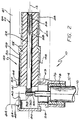
- Figure 1 illustrates a right angle coaxial termination device 10 which includes largely coaxial conductors extending along the main axis 12 of the device, and which can connect to a coaxial cable 14 extending along a perpendicular axis 16.
- the particular termination device 10 includes one outer conductor 20 and two spaced inner conductors 22,24, and the coaxial cable 14 similarly has two inner conductors.
- the inner and outer conductors of the termination device are separated by an insulator 25.
- the termination device has rear and front end portions 26,28, with the insulator ending at the rear end portion to leave a cavity 30 where the inner termination conductors 22,24 can be connected to corresponding inner conductors 32,34 ( Figure 3) of the coaxial cable 14.
- the inner termination conductors such as 22 have slots 36 that each receive an inner conductor of the cable 14. Completion of termination is accomplished by permanently joining corresponding inner conductors such as 22 and 32, as by soldering them together.
- the outer termination conductor 20 has an access aperture 40 at one side 41 and a termination aperture 78 at an opposite side 43. The tip of a soldering iron or other joining apparatus can be inserted through the access aperture to join the ends of corresponding inner conductors such as 22 and 32. After the joining operation has been completed, the access aperture 40 must be closed to prevent RF (radio frequency) leakage and to seal out dirt.
- the termination device includes a sleeve 42 mounted about the outer conductor 20 and slideable therealong.
- the sleeve has rear and front end portions 44,46.
- the sleeve is kept in an open position shown in solid lines in Figure 2 during the soldering operation. After soldering is completed, the sleeve is slid in a rearward direction to the position shown at 42A wherein the rear end portion of the sleeve lies over the access aperture 40 to close it.
- the sleeve has an outwardly-extending flange 50 at its rear end, which facilitates sliding of the sleeve along the length direction of the termination device, as with the technician's fingers or automatically by a coupling as described below.
- the termination device is used for "plugging into,” or connection, to a coupling 54 which receives or delivers signals through the coaxial conductors of the termination device.
- the inner coaxial conductors of the termination device have clip-like ends 56 which can receive and resiliently contact pins 58 (shown in chain line) of the coupling, while an outer conductor 60 (shown in chain line) of the coupling contacts the outer termination conductor 20.
- the coupling includes a housing 61 forming an outer isolator with a front end forming a shoulder 62 that can move against the flange 50 at the rear of the sleeve 42, to slide the sleeve to its closed position and prevent forward movement of the sleeve after the termination device has been mated to the coupling.
- a flange indicated at 68 could be provided at the other side of the sleeve.
- the coupling surrounds the sleeve, and the front portion 64 of the coupling housing presses firmly against the rear of the sleeve to press it against the side of the termination outer conductor 20 to avoid a gap of appreciable width between the rear of the sleeve and the outer conductor of the termination device.
- the outer conductor 20 of the termination device is largely cylindrical at the part which holds the sleeve.
- the sleeve 42 is constructed of sheet metal rolled into a cylindrical shape, but with a gap 66 ( Figure 1) that allows the sleeve to be slipped onto the termination device over shoulders 70 or 72 at the rear and front portions of the termination device. The shoulders prevent loss of the sleeve.
- One side of the sleeve which forms the flange 50 extends further rearwards than the opposite side of the sleeve which has a cutout 74 that avoids interference with a tube 76 that forms a termination aperture 78 that receives the coaxial cable 14.
- the termination device 10 is connected to the coaxial conductor 14 by first stripping away insulation around the inner conductors 32,34 of the coaxial cable, and inserting the coaxial cable into the termination aperture 78 to the position shown in the figures.
- the outer conductor of cable 14 is crimped in place.
- solder, flux, and the tip of a soldering tool are projected through the access aperture 40 to solder together the corresponding inner conductors of the coaxial cable 14 and of the termination device 10.
- a technician can then press rearwardly on the flange 50 to close the sleeve.
- the termination device with the coaxial cable connected thereto, is then ready for plugging into the coupling 54.
- the access aperture 40 and termination aperture 78 lie on opposite sides of the outer conductor 20 of the termination device, at locations spaced from the extreme rear end 80 of the device.
- the technician has access to the entire circumference of each inner conductor 32,34 of the coaxial cable (as shown in Figure 3), which facilitates making a good solder joint. This is preferable to access through the extreme rear end 80 of the termination device.
- the access aperture 40 is automatically held closed when the termination device is plugged into the housing of a coupling, when access is not required. If there is a poor solder joint, the sleeve can be retracted for new access to the joint.
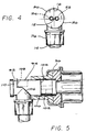
- Figure 5 illustrates another termination device 92 with a modified sleeve 94, and a coupling 96 with a modified housing.
- the coupling 96 includes a clip 100 with resilient lances or fingers 102 that can engage the front end 104 of the sleeve 94 to prevent it from moving forwardly.
- the cutout 106 in the sleeve is just large enough to limit rearward movement of the sleeve to a position at which the rear portion of the sleeve covers the access aperture 108 in the outer conductor 110 of the termination device.
- the invention provides a coaxial termination device which enables relatively good access to the ends of inner conductors to facilitate joining them as by soldering, and which facilitates closing of the access aperture, all in a low cost and easily operated device.
- the access aperture lies at a side of the termination outer conductor, which is opposite the termination aperture through which the coaxial cable is received, and closing of the access aperture is by means of a sleeve which can slide on the termination device.
- a coupling to which the front end of the termination device is mated, includes means for holding the sleeve in its closed position. While the particular termination device which is shown has two inner conductors, the invention is useful for a device with one, or more than two, inner conductors.
Landscapes
- Coupling Device And Connection With Printed Circuit (AREA)
- Processing Of Terminals (AREA)
Claims (5)
- Koaxial-Anschlußvorrichtung mit einem elektrisch leitenden, im wesentlichen zylindrischen Außenleiter (20), der langgestreckt ist und über seine Länge mit im Abstand angeordneten vorderen und hinteren Endbereichen und mit einer ersten und einer zweiten gegenüberliegenden Seite versehen ist, wobei der hintere Endbereich ein geschlossenes hinteres Ende besitzt und der vordere Endbereich offen ist, wobei der hintere Endbereich des Außenleiters eine Aufnahmeöffnung (78) und eine Zugriffsöffnung (40, 108) an der ersten bzw. der zweiten Seite besitzt, mit einem um die Aufnahmeöffnung (78) liegenden und sich im wesentlichen senkrecht zur Länge des Außenleiters (20) erstreckenden Rohr (76), mit mindestens einem sich im Außenleiter (20) zwischen dem vorderen Endbereich und den Öffnungen (40, 108, 78) erstreckenden Innenleiter (22, 32), mit einem zwischen dem Innenleiter (22, 32) und dem Außenleiter (20) liegenden Isolator (25), wobei der Innenleiter (22, 32) sich vom Isolator (25) nach hinten erstreckt, gekennzeichnet durch eine Hülse (42), die um den Außenleiter (20) liegt und auf diesem nach vorne und nach hinten verschiebbar ist, um in einer Offen- bzw. einer Geschlossenstellung zu liegen, wobei die Hülse (42) an derselben Seite wie die Zugriffsöffnung (40, 108) einen die Öffnung verschließenden Bereich besitzt, der die Zugriffsöffnung (40, 108) in der Geschlossenstellung schließt und in der Offenstellung öffnet und die Hülse (42) an derselben Seite wie die Aufnahmeöffnung (78) eine Aussparung besitzt, um eine Kollision mit dem Rohr (76) zu verhindern.
- Koaxial-Anschlußvorrichtung nach Anspruch 1, gekennzeichnet durch einen Halter (100), der sich um den Außenleiter erstreckt und der mit dem vorderen Bereich (104) der Hülse (94) dann, wenn die Hülse sich in ihrer Geschlossenstellung befindet, in Eingriff ist, um ein Verschieben der Hülse (94) nach vorne zu verhindern.
- Koaxial-Anschlußvorrichtung nach Anspruch 1 oder 2, dadurch gekennzeichnet, daß eine Kupplung (54) vorgesehen ist, die mit Innen- und Außenleitern (58, 60) versehen ist, welche so ausgebildet sind, daß sie mit den Vorderenden der Leiter der Anschlußvorrichtung (22, 24, 20) zusammenpassen, und die ein Gehäuse (61) aufweist, das den hinteren Bereich (44, 50) der Hülse (42) zum Außenleiter (20) hin drückt, um jeglichen Spalt zwischen der Hülse (42) und dem Außenleiter (20) zu minimieren.
- Koaxial-Anschlußvorrichtung nach einem der vorhergehenden Ansprüche, dadurch gekennzeichnet, daß der hintere Bereich der Hülse (42, 94) einen nach außen vorstehenden Rand (50) bildet, um dadurch das Verschieben der Hülse zu erleichtern.
- Koaxial-Anschlußvorrichtung nach einem der vorhergehenden Ansprüche, dadurch gekennzeichnet, daß der Außenleiter (20) vor bzw. hinter der Hülse (42, 94) liegende vordere und hintere Schultern aufweist und daß die Hülse im wesentlichen zylindrisch ist, jedoch einen Spalt (66) besitzt, der ein Aufweiten zum Schieben über eine der Schultern ermöglicht und die Hülse dann zum Zusammenziehen neigt, so daß sie an die Schultern stößt, um ihr zu weites Vor- und Zurückschieben zu verhindern und dadurch die Hülse zu sichern.
Applications Claiming Priority (2)
| Application Number | Priority Date | Filing Date | Title |
|---|---|---|---|
| US07/307,107 US4932898A (en) | 1989-02-07 | 1989-02-07 | Termination system for coaxial conductor |
| US307107 | 1999-05-07 |
Publications (2)
| Publication Number | Publication Date |
|---|---|
| EP0382374A1 EP0382374A1 (de) | 1990-08-16 |
| EP0382374B1 true EP0382374B1 (de) | 1994-09-07 |
Family
ID=23188271
Family Applications (1)
| Application Number | Title | Priority Date | Filing Date |
|---|---|---|---|
| EP90300771A Expired - Lifetime EP0382374B1 (de) | 1989-02-07 | 1990-01-25 | Koaxialleiter-Abschlussteckersystem |
Country Status (6)
| Country | Link |
|---|---|
| US (1) | US4932898A (de) |
| EP (1) | EP0382374B1 (de) |
| JP (1) | JPH02231913A (de) |
| KR (1) | KR900013670A (de) |
| CA (1) | CA1327999C (de) |
| DE (1) | DE69012160T2 (de) |
Cited By (1)
| Publication number | Priority date | Publication date | Assignee | Title |
|---|---|---|---|---|
| WO2016123294A1 (en) * | 2015-01-30 | 2016-08-04 | Commscope Technologies Llc | Assembly comprising coaxial cable and right-angled coaxial connector and manufacturing method thereof |
Families Citing this family (21)
| Publication number | Priority date | Publication date | Assignee | Title |
|---|---|---|---|---|
| DE69009341T2 (de) * | 1989-08-11 | 1995-01-05 | Murata Manufacturing Co | Stecker. |
| NO175334C (no) * | 1992-03-26 | 1994-09-28 | Kaare Johnsen | Kontakthus for koaksialkabel |
| US5362255A (en) * | 1993-09-14 | 1994-11-08 | Itt Corporation | Coaxial connector |
| DE4436342A1 (de) * | 1994-10-12 | 1996-04-18 | Rheydt Kabelwerk Ag | Koaxialsteckverbinder zum Konfektionieren eines koaxialen Hochfrequenzkabels |
| AU4684999A (en) * | 1998-06-30 | 2000-01-17 | John Mezzalingua Associates, Inc | Coaxial cable connector with angled connection |
| FR2818448B1 (fr) * | 2000-12-18 | 2006-02-03 | Sagem | Connecteur de puissance pour carte a circuit imprime |
| US6676445B2 (en) * | 2002-01-25 | 2004-01-13 | Tyco Electronics Corporation | Coaxial cable connector apparatus, methods and articles of manufacture for angle or in-line applications |
| US6860761B2 (en) * | 2003-01-13 | 2005-03-01 | Andrew Corporation | Right angle coaxial connector |
| US7144279B2 (en) * | 2004-12-30 | 2006-12-05 | Homac Mfg. Company | Electrical connector including viewing windows and associated methods |
| US6997759B1 (en) | 2004-12-30 | 2006-02-14 | Homac Mfg. Company | Electrical connector including moveable cable seating indicators and associated methods |
| US20060286862A1 (en) * | 2004-12-30 | 2006-12-21 | Homac Mfg. Company | Reusable insulating and sealing structure including tethered cap and associated methods |
| US7717740B2 (en) * | 2004-12-30 | 2010-05-18 | Thomas & Betts International, Inc. | Electrical connector including viewing window assembly and associated methods |
| US7094094B2 (en) * | 2004-12-30 | 2006-08-22 | Homac Mfg Company | Electrical connector including insulating boots and associated methods |
| US7118427B2 (en) * | 2004-12-30 | 2006-10-10 | Homac Mfg Company | Electrical connector including removable tether and cap assemblies and associated methods |
| DE102007031727A1 (de) * | 2006-08-31 | 2008-03-20 | Zf Friedrichshafen Ag | Verbindungselement zum Verbinden von elektrischen Leitern |
| DE202008014409U1 (de) * | 2008-10-29 | 2009-01-22 | Rosenberger Hochfrequenztechnik Gmbh & Co. Kg | HF-Winkelsteckverbinder |
| GB2469023B (en) * | 2009-03-30 | 2013-01-02 | Tyco Electronics Ltd Uk | Coaxial connector and method of assembling one |
| US7753689B1 (en) * | 2009-05-12 | 2010-07-13 | Hon Hai Precision Ind. Co., Ltd. | Plug connector with right angle cover |
| JP5630365B2 (ja) * | 2011-04-13 | 2014-11-26 | オムロン株式会社 | コネクタ用接続端子およびそれを用いたコネクタ |
| US8628352B2 (en) * | 2011-07-07 | 2014-01-14 | John Mezzalingua Associates, LLC | Coaxial cable connector assembly |
| US20250023279A1 (en) * | 2023-07-12 | 2025-01-16 | Aptiv Technologies AG | Terminal assembly with terminal inspection port and methods of assembling same |
Family Cites Families (9)
| Publication number | Priority date | Publication date | Assignee | Title |
|---|---|---|---|---|
| US3530425A (en) * | 1968-10-22 | 1970-09-22 | Jerrold Electronics Corp | Coaxial cable connector |
| DE2215757C3 (de) * | 1972-03-30 | 1975-08-28 | Siemens Ag, 1000 Berlin Und 8000 Muenchen | Stecker- bzw. Buchsenteil einer Steckvorrichtung für Koaxialkabel |
| US4025150A (en) * | 1975-12-12 | 1977-05-24 | Gte Sylvania Incorporated | Equipment housing for communication system |
| DE2643373A1 (de) * | 1976-09-27 | 1978-03-30 | Morat Joh Soehne Jms | Kabelinstallations- und -anschlusseinrichtung fuer hochfrequenzwinkelstecker und/oder -buchsen |
| US4261630A (en) * | 1979-06-18 | 1981-04-14 | Motorola, Inc. | Hybrid RF termination and connector system |
| US4655534A (en) * | 1985-03-15 | 1987-04-07 | E. F. Johnson Company | Right angle coaxial connector |
| US4678261A (en) * | 1986-04-23 | 1987-07-07 | Hirose Electric Co., Ltd. | L-type coaxial plug connector |
| US4722222A (en) * | 1986-09-25 | 1988-02-02 | Skisonics Corporation | Ski speedometer |
| US4772222A (en) * | 1987-10-15 | 1988-09-20 | Amp Incorporated | Coaxial LMC connector |
-
1989
- 1989-02-07 US US07/307,107 patent/US4932898A/en not_active Expired - Fee Related
- 1989-08-16 KR KR1019890011616A patent/KR900013670A/ko not_active Withdrawn
- 1989-09-05 CA CA000610311A patent/CA1327999C/en not_active Expired - Fee Related
- 1989-09-27 JP JP1251706A patent/JPH02231913A/ja active Pending
-
1990
- 1990-01-25 DE DE69012160T patent/DE69012160T2/de not_active Expired - Fee Related
- 1990-01-25 EP EP90300771A patent/EP0382374B1/de not_active Expired - Lifetime
Cited By (1)
| Publication number | Priority date | Publication date | Assignee | Title |
|---|---|---|---|---|
| WO2016123294A1 (en) * | 2015-01-30 | 2016-08-04 | Commscope Technologies Llc | Assembly comprising coaxial cable and right-angled coaxial connector and manufacturing method thereof |
Also Published As
| Publication number | Publication date |
|---|---|
| EP0382374A1 (de) | 1990-08-16 |
| JPH02231913A (ja) | 1990-09-13 |
| US4932898A (en) | 1990-06-12 |
| KR900013670A (ko) | 1990-09-06 |
| DE69012160D1 (de) | 1994-10-13 |
| CA1327999C (en) | 1994-03-22 |
| DE69012160T2 (de) | 1995-02-02 |
Similar Documents
| Publication | Publication Date | Title |
|---|---|---|
| EP0382374B1 (de) | Koaxialleiter-Abschlussteckersystem | |
| US4227765A (en) | Coaxial electrical connector | |
| US4339166A (en) | Connector | |
| US5775927A (en) | Self-terminating coaxial connector | |
| US5273458A (en) | Method and apparatus for crimping an electrical terminal to a coaxial cable conductor, and terminal and coaxial cable connector therefor | |
| US5725387A (en) | System for terminating the shield of a high speed cable | |
| US5718607A (en) | System for terminating the shield of a high speed cable | |
| EP0432144B1 (de) | Zusammenbau von elektrischen Verbindern | |
| KR100513690B1 (ko) | 케이블커넥터 조립체 | |
| US4690481A (en) | Coaxial coupling | |
| CA2023463A1 (en) | Coaxial cable connector | |
| HK6695A (en) | Electrical connector | |
| JP2000353559A (ja) | 同軸ケーブルを印刷回路カードに電気的に結合するための装置 | |
| CA2170639C (en) | Coaxial connector | |
| US5495075A (en) | Coaxial connector | |
| EP1451903A1 (de) | Anlötverbinder für koaxialkabel | |
| US4734051A (en) | Electrical connector butt contact | |
| US6371806B1 (en) | Cable end connector having accurately positioned connection terminal therein | |
| EP1642362B1 (de) | Koaxialkontakt | |
| CN101060219B (zh) | 小型同轴电缆接合连接器组件和它的壁装配安装工具 | |
| EP0630075B1 (de) | Steckverbinder mit Betätigungshebel und Verfahren für die Zusammensetzung und Verbindung | |
| US4897050A (en) | Method and apparatus for making coaxial couplings | |
| US5098314A (en) | Eyelet termination for coaxial cable | |
| US5090915A (en) | Self-terminating coaxial tap connector with external termination element | |
| US20030040219A1 (en) | RF cable connector assembly |
Legal Events
| Date | Code | Title | Description |
|---|---|---|---|
| PUAI | Public reference made under article 153(3) epc to a published international application that has entered the european phase |
Free format text: ORIGINAL CODE: 0009012 |
|
| AK | Designated contracting states |
Kind code of ref document: A1 Designated state(s): DE FR GB IT SE |
|
| 17P | Request for examination filed |
Effective date: 19900907 |
|
| 17Q | First examination report despatched |
Effective date: 19930625 |
|
| GRAA | (expected) grant |
Free format text: ORIGINAL CODE: 0009210 |
|
| AK | Designated contracting states |
Kind code of ref document: B1 Designated state(s): DE FR GB IT SE |
|
| PG25 | Lapsed in a contracting state [announced via postgrant information from national office to epo] |
Ref country code: IT Free format text: LAPSE BECAUSE OF FAILURE TO SUBMIT A TRANSLATION OF THE DESCRIPTION OR TO PAY THE FEE WITHIN THE PRE;WARNING: LAPSES OF ITALIAN PATENTS WITH EFFECTIVE DATE BEFORE 2007 MAY HAVE OCCURRED AT ANY TIME BEFORE 2007. THE CORRECT EFFECTIVE DATE MAY BE DIFFERENT FROM THE ONE RECORDED.SCRIBED TIME-LIMIT Effective date: 19940907 |
|
| REF | Corresponds to: |
Ref document number: 69012160 Country of ref document: DE Date of ref document: 19941013 |
|
| ET | Fr: translation filed | ||
| PG25 | Lapsed in a contracting state [announced via postgrant information from national office to epo] |
Ref country code: GB Effective date: 19950125 |
|
| PG25 | Lapsed in a contracting state [announced via postgrant information from national office to epo] |
Ref country code: SE Effective date: 19950126 |
|
| EAL | Se: european patent in force in sweden |
Ref document number: 90300771.4 |
|
| PLBE | No opposition filed within time limit |
Free format text: ORIGINAL CODE: 0009261 |
|
| STAA | Information on the status of an ep patent application or granted ep patent |
Free format text: STATUS: NO OPPOSITION FILED WITHIN TIME LIMIT |
|
| 26N | No opposition filed | ||
| GBPC | Gb: european patent ceased through non-payment of renewal fee |
Effective date: 19950125 |
|
| PG25 | Lapsed in a contracting state [announced via postgrant information from national office to epo] |
Ref country code: DE Effective date: 19951003 |
|
| EUG | Se: european patent has lapsed |
Ref document number: 90300771.4 |
|
| PGFP | Annual fee paid to national office [announced via postgrant information from national office to epo] |
Ref country code: FR Payment date: 19981231 Year of fee payment: 10 |
|
| PG25 | Lapsed in a contracting state [announced via postgrant information from national office to epo] |
Ref country code: FR Free format text: LAPSE BECAUSE OF NON-PAYMENT OF DUE FEES Effective date: 20000929 |
|
| REG | Reference to a national code |
Ref country code: FR Ref legal event code: ST |