EP0382586A1 - Dispositif pour la production du froid et/ou de la chaleur par réaction solide-gaz - Google Patents
Dispositif pour la production du froid et/ou de la chaleur par réaction solide-gaz Download PDFInfo
- Publication number
- EP0382586A1 EP0382586A1 EP90400064A EP90400064A EP0382586A1 EP 0382586 A1 EP0382586 A1 EP 0382586A1 EP 90400064 A EP90400064 A EP 90400064A EP 90400064 A EP90400064 A EP 90400064A EP 0382586 A1 EP0382586 A1 EP 0382586A1
- Authority
- EP
- European Patent Office
- Prior art keywords
- reactor
- heat
- gas
- reactors
- intended
- Prior art date
- Legal status (The legal status is an assumption and is not a legal conclusion. Google has not performed a legal analysis and makes no representation as to the accuracy of the status listed.)
- Granted
Links
- 238000006243 chemical reaction Methods 0.000 title claims abstract description 18
- 150000003839 salts Chemical class 0.000 claims abstract description 31
- 238000010521 absorption reaction Methods 0.000 claims abstract description 10
- 238000004891 communication Methods 0.000 claims abstract description 8
- QGZKDVFQNNGYKY-UHFFFAOYSA-N Ammonia Chemical compound N QGZKDVFQNNGYKY-UHFFFAOYSA-N 0.000 claims description 46
- 229910021529 ammonia Inorganic materials 0.000 claims description 23
- UXVMQQNJUSDDNG-UHFFFAOYSA-L Calcium chloride Chemical compound [Cl-].[Cl-].[Ca+2] UXVMQQNJUSDDNG-UHFFFAOYSA-L 0.000 claims description 16
- 239000001110 calcium chloride Substances 0.000 claims description 15
- 235000011148 calcium chloride Nutrition 0.000 claims description 15
- 229910001628 calcium chloride Inorganic materials 0.000 claims description 15
- 229910021586 Nickel(II) chloride Inorganic materials 0.000 claims description 9
- QMMRZOWCJAIUJA-UHFFFAOYSA-L nickel dichloride Chemical compound Cl[Ni]Cl QMMRZOWCJAIUJA-UHFFFAOYSA-L 0.000 claims description 9
- 229910001626 barium chloride Inorganic materials 0.000 claims description 6
- WDIHJSXYQDMJHN-UHFFFAOYSA-L barium chloride Chemical compound [Cl-].[Cl-].[Ba+2] WDIHJSXYQDMJHN-UHFFFAOYSA-L 0.000 claims description 6
- 229910021577 Iron(II) chloride Inorganic materials 0.000 claims description 4
- TWRXJAOTZQYOKJ-UHFFFAOYSA-L Magnesium chloride Chemical compound [Mg+2].[Cl-].[Cl-] TWRXJAOTZQYOKJ-UHFFFAOYSA-L 0.000 claims description 4
- 229910021380 Manganese Chloride Inorganic materials 0.000 claims description 4
- GLFNIEUTAYBVOC-UHFFFAOYSA-L Manganese chloride Chemical compound Cl[Mn]Cl GLFNIEUTAYBVOC-UHFFFAOYSA-L 0.000 claims description 4
- NMCUIPGRVMDVDB-UHFFFAOYSA-L iron dichloride Chemical compound Cl[Fe]Cl NMCUIPGRVMDVDB-UHFFFAOYSA-L 0.000 claims description 4
- 239000011565 manganese chloride Substances 0.000 claims description 4
- 235000002867 manganese chloride Nutrition 0.000 claims description 4
- 229910001629 magnesium chloride Inorganic materials 0.000 claims description 2
- 239000007787 solid Substances 0.000 abstract description 3
- 238000009434 installation Methods 0.000 description 30
- 238000003795 desorption Methods 0.000 description 10
- 239000012080 ambient air Substances 0.000 description 7
- 239000000126 substance Substances 0.000 description 7
- 238000010586 diagram Methods 0.000 description 6
- 239000003570 air Substances 0.000 description 5
- 238000004378 air conditioning Methods 0.000 description 4
- XLYOFNOQVPJJNP-UHFFFAOYSA-N water Substances O XLYOFNOQVPJJNP-UHFFFAOYSA-N 0.000 description 4
- FAPWRFPIFSIZLT-UHFFFAOYSA-M Sodium chloride Chemical compound [Na+].[Cl-] FAPWRFPIFSIZLT-UHFFFAOYSA-M 0.000 description 2
- 238000010276 construction Methods 0.000 description 2
- 238000001816 cooling Methods 0.000 description 2
- 238000010438 heat treatment Methods 0.000 description 2
- 239000007788 liquid Substances 0.000 description 2
- 238000004519 manufacturing process Methods 0.000 description 2
- JHJLBTNAGRQEKS-UHFFFAOYSA-M sodium bromide Chemical compound [Na+].[Br-] JHJLBTNAGRQEKS-UHFFFAOYSA-M 0.000 description 2
- 150000001875 compounds Chemical class 0.000 description 1
- 238000009833 condensation Methods 0.000 description 1
- 230000005494 condensation Effects 0.000 description 1
- 230000003111 delayed effect Effects 0.000 description 1
- 230000000694 effects Effects 0.000 description 1
- 238000004146 energy storage Methods 0.000 description 1
- 239000012530 fluid Substances 0.000 description 1
- 238000005338 heat storage Methods 0.000 description 1
- 238000005057 refrigeration Methods 0.000 description 1
- 230000002441 reversible effect Effects 0.000 description 1
- 239000011780 sodium chloride Substances 0.000 description 1
- 238000001179 sorption measurement Methods 0.000 description 1
- 229910001631 strontium chloride Inorganic materials 0.000 description 1
- AHBGXTDRMVNFER-UHFFFAOYSA-L strontium dichloride Chemical compound [Cl-].[Cl-].[Sr+2] AHBGXTDRMVNFER-UHFFFAOYSA-L 0.000 description 1
- 239000011592 zinc chloride Substances 0.000 description 1
- 235000005074 zinc chloride Nutrition 0.000 description 1
- JIAARYAFYJHUJI-UHFFFAOYSA-L zinc dichloride Chemical compound [Cl-].[Cl-].[Zn+2] JIAARYAFYJHUJI-UHFFFAOYSA-L 0.000 description 1
- NWONKYPBYAMBJT-UHFFFAOYSA-L zinc sulfate Chemical compound [Zn+2].[O-]S([O-])(=O)=O NWONKYPBYAMBJT-UHFFFAOYSA-L 0.000 description 1
- 229910000368 zinc sulfate Inorganic materials 0.000 description 1
- 239000011686 zinc sulphate Substances 0.000 description 1
- 235000009529 zinc sulphate Nutrition 0.000 description 1
Images



Classifications
-
- F—MECHANICAL ENGINEERING; LIGHTING; HEATING; WEAPONS; BLASTING
- F25—REFRIGERATION OR COOLING; COMBINED HEATING AND REFRIGERATION SYSTEMS; HEAT PUMP SYSTEMS; MANUFACTURE OR STORAGE OF ICE; LIQUEFACTION SOLIDIFICATION OF GASES
- F25B—REFRIGERATION MACHINES, PLANTS OR SYSTEMS; COMBINED HEATING AND REFRIGERATION SYSTEMS; HEAT PUMP SYSTEMS
- F25B17/00—Sorption machines, plants or systems, operating intermittently, e.g. absorption or adsorption type
- F25B17/08—Sorption machines, plants or systems, operating intermittently, e.g. absorption or adsorption type the absorbent or adsorbent being a solid, e.g. salt
-
- F—MECHANICAL ENGINEERING; LIGHTING; HEATING; WEAPONS; BLASTING
- F28—HEAT EXCHANGE IN GENERAL
- F28D—HEAT-EXCHANGE APPARATUS, NOT PROVIDED FOR IN ANOTHER SUBCLASS, IN WHICH THE HEAT-EXCHANGE MEDIA DO NOT COME INTO DIRECT CONTACT
- F28D20/00—Heat storage plants or apparatus in general; Regenerative heat-exchange apparatus not covered by groups F28D17/00 or F28D19/00
- F28D20/003—Heat storage plants or apparatus in general; Regenerative heat-exchange apparatus not covered by groups F28D17/00 or F28D19/00 using thermochemical reactions
-
- Y—GENERAL TAGGING OF NEW TECHNOLOGICAL DEVELOPMENTS; GENERAL TAGGING OF CROSS-SECTIONAL TECHNOLOGIES SPANNING OVER SEVERAL SECTIONS OF THE IPC; TECHNICAL SUBJECTS COVERED BY FORMER USPC CROSS-REFERENCE ART COLLECTIONS [XRACs] AND DIGESTS
- Y02—TECHNOLOGIES OR APPLICATIONS FOR MITIGATION OR ADAPTATION AGAINST CLIMATE CHANGE
- Y02A—TECHNOLOGIES FOR ADAPTATION TO CLIMATE CHANGE
- Y02A30/00—Adapting or protecting infrastructure or their operation
- Y02A30/27—Relating to heating, ventilation or air conditioning [HVAC] technologies
-
- Y—GENERAL TAGGING OF NEW TECHNOLOGICAL DEVELOPMENTS; GENERAL TAGGING OF CROSS-SECTIONAL TECHNOLOGIES SPANNING OVER SEVERAL SECTIONS OF THE IPC; TECHNICAL SUBJECTS COVERED BY FORMER USPC CROSS-REFERENCE ART COLLECTIONS [XRACs] AND DIGESTS
- Y02—TECHNOLOGIES OR APPLICATIONS FOR MITIGATION OR ADAPTATION AGAINST CLIMATE CHANGE
- Y02B—CLIMATE CHANGE MITIGATION TECHNOLOGIES RELATED TO BUILDINGS, e.g. HOUSING, HOUSE APPLIANCES OR RELATED END-USER APPLICATIONS
- Y02B30/00—Energy efficient heating, ventilation or air conditioning [HVAC]
- Y02B30/62—Absorption based systems
-
- Y—GENERAL TAGGING OF NEW TECHNOLOGICAL DEVELOPMENTS; GENERAL TAGGING OF CROSS-SECTIONAL TECHNOLOGIES SPANNING OVER SEVERAL SECTIONS OF THE IPC; TECHNICAL SUBJECTS COVERED BY FORMER USPC CROSS-REFERENCE ART COLLECTIONS [XRACs] AND DIGESTS
- Y02—TECHNOLOGIES OR APPLICATIONS FOR MITIGATION OR ADAPTATION AGAINST CLIMATE CHANGE
- Y02E—REDUCTION OF GREENHOUSE GAS [GHG] EMISSIONS, RELATED TO ENERGY GENERATION, TRANSMISSION OR DISTRIBUTION
- Y02E60/00—Enabling technologies; Technologies with a potential or indirect contribution to GHG emissions mitigation
- Y02E60/14—Thermal energy storage
Definitions
- the present invention relates to a device for producing cold and / or heat by solid-gas reaction.
- thermochemical pump used for the operation of the system itself; electrical energy is possibly only used for the circulation of heat transfer fluids, - a reversible reaction between a solid and a gas of the type is used as "chemical engine”:
- the reaction is exothermic in direction 1, which means that in this direction it produces heat and endothermic in direction 2, that is to say that in this direction it produces cold.
- Such a system allows energy storage in chemical form and has various fields of application.
- the system is called a "chemical heat pump”.
- Such a system also allows the production, from a heat source at the temperature T′s, of heat at the temperature T′u such that: T′u> T′s
- the system is called "chemical thermo transformer”.
- the use of the heat or cold produced is simultaneous with the consumption of energy at high temperature (Ts, T′s, T ⁇ s) or delayed over time (storage effect).
- French patent application is known from No. 87 07210 a device for producing cold and / or heat which comprises two reactors containing the same solid compound, a condenser and an evaporator.
- the present invention therefore aims to provide a device for producing cold and / or heat which is of improved efficiency.
- the invention relates to a device for producing cold and / or heat by solid-gas reaction
- a device for producing cold and / or heat by solid-gas reaction comprising first and second reactors which each contain a salt capable of reacting by absorption with a gas according to an exothermic reaction.
- the first reactor being in communication in a first operating phase with an enclosure intended to retain the gas
- the second reactor being in communication, in the first operating phase with an enclosure intended to release the gas, characterized in that each reactor comprises a different salt.
- the operation of the devices according to the invention is based on the reaction between a salt and a gas.
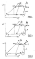
- FIG. 1 which includes equilibrium lines of the salts used.
- FIG. 2A shows a device for producing cold by solid-gas reaction according to a first embodiment of the invention.
- the device comprises first and second chemical reactors 10, 12, a condenser 14 and an evaporator 16.
- Each chemical reactor 10, 12 is formed of an enclosure, for example metallic, in which is placed a quantity of salt.
- the reactor 10 contains NiCl2, which originally comes in the form of a complex with ammonia and the reactor 12 CaCl2.
- the condenser 14 and the evaporator 16 are of conventional construction and are arranged so as to be able to exchange heat with their environment.
- the first operating phase consists in heating the first chemical reactor 10 to a temperature of 280 ° C., for example by circulating superheated steam in a heat exchanger (not shown) arranged inside this reactor.
- the salt originally rich in ammonia, releases this ammonia which passes through a conduit 18 to the condenser 14.
- the condensation of the ammonia releases heat at a temperature of 40 ° C. which is recovered by water introduced into the condenser at room temperature which in the example illustrated is 30 to 35 ° C.
- the ammonia in the liquid state then passes through a conduit 20 in the evaporator 16 where it evaporates while absorbing heat and thus creating cold at a temperature of -25 ° C.
- the ammonia vapor finally passes through a line 22 to the second reactor 12 where it is absorbed by the CaCl2 salt at a temperature below 52 ° C.
- the two reactors 10, 12 are connected by a heat transfer device 24.
- This device can comprise a heat exchanger or heat transfer system in which a heat transfer liquid circulates.
- the heat transfer device 24 may comprise a heat pipe 24, for example that described in French patent application No. 88 04165.
- a second operating phase represented in FIG. 2B, the reactor 10 is connected to the evaporator 16 by a conduit 26 and the reactor 12 is connected to the condenser 14 by a conduit 28.
- the heat transfer system 24 between the two reactors 10, 12 is put into operation.
- the salt in reactor 10, which is poor in ammonia, absorbs ammonia and passes to a temperature below 180 ° C.
- the heat of absorption of NiCl2 is transferred by the heat transfer system 24 to CaCl2 in the reactor 12 and serves as a heat source for the desorption of CaCl2 which, at the end of the first phase, is rich in ammonia.
- the salt in reactor 12 desorbs ammonia which passes first to condenser 14 and then to evaporator 16 as in the first phase.
- the choice of the salts used in reactors 10 and 12 and the use of the heat transfer device 24 between the reactors makes it possible to create cold at a temperature of -25 ° C., in the example given of continuously. It follows that at the end of the second phase the reactors 10 and 12 will be reconnected according to the circuit of FIG. 2A.
- FIG. 3 A complete circuit allowing the continuous operation of the device is shown in FIG. 3.
- the conduits 18, 22, 26 and 28 as well as the heat pipe 24 are each provided with a respective valve 30 allowing the passage from the first to the second phases and vice versa.
- the salts used are such that there is a difference between the temperature of absorption of the salt in the reactor 10 and the temperature of desorption of the salt in the reactor 12.
- the difference T therefore has a minimum value of 32 ° C., a value which ensures efficient heat transfer by the heat transfer system 24.
- the performance of a device for producing cold and / or heat by solid-gas reaction can be evaluated using the economic concept of the coefficient of performance or COP.
- the COP is defined by the relation: expression in which H e is the heat of release of the gas, ⁇ H R is the heat of desorption reaction of the gas of the salt ⁇ C p ⁇ T is the sensible heat to be supplied to the reactor and to the salt between the two temperature levels corresponding to the reaction absorption and desorption reaction.
- FIG. 4 to 7 Clapeyron diagrams for devices using two different salts and which are intended to produce either cold or heat at a given temperature.
- the installation used and its operation correspond to those of the device in FIG. 3, only the operating temperatures and the salts change.
- the installation in this example is intended to produce fresh air at 5 ° C for the air conditioning of a building.
- Reactor 10 contains FeCl2 and reactor 12 contains CaCl2.
- the installation requires a heat source at 210 ° C and releases heat into the ambient air which has a temperature of 30/35 ° C.
- the heat of absorption of FeCl2 in the reactor 10 at a temperature of 125 to 145 ° C passes through the heat transfer device 24 and is used as heat of desorption of CaCl2 in the reactor 12 at a temperature of 95 to 115 ° C.
- the installation in this example is intended to produce cold at -25 ° C for refrigeration.
- Reactor 10 contains MgCl2 and reactor 12 contains CaCl2.
- the installation requires a heat source at 210 ° C and releases heat into the ambient air or water which has a temperature of 15 to 20 ° C.
- this installation is intended to produce fresh air at 5 ° C for the air conditioning of a building.
- Reactor 10 contains FeCl2 and reactor 12 contains CaCl2.
- the installation uses a heat source at 190 ° C and releases heat into the ambient air or water that has a temperature of 15 to 20 ° C.
- This installation is also intended to produce fresh air, but at a temperature of 0 ° C.
- the installation produces heat at a temperature of 90 ° C and therefore it can be used for air conditioning and heating.
- the installation requires a heat source at 280 ° C and releases heat in water circulating in the condenser at a temperature of 15 to 20 ° C.
- Reactor 10 contains NiCl2 and reactor 12 contains MnCl2.
- FIGs 8 and 9 there is shown an installation according to another embodiment of the invention and which comprises four reactors which contain three different salts.
- the device represented in FIG. 8A is intended to produce fresh air at 5 ° C. by solid-gas reaction and comprises four reactors 32, 34, 36 and 38 of construction similar to those of FIG. 2 but does not use or condenser or evaporator.
- the reactors 32 and 36 contain BaCl2
- the reactor 34 contains NiCl le
- the salts in reactors 34 and 36 are in the form of a complex with ammonia.
- the reactor 34 is heated to a temperature of 270 ° C. Salt, originally rich in ammonia, releases this ammonia which passes through a pipe 40 to the reactor 32 where it is absorbed by the BaCl2 releasing heat at a temperature of 40 ° C which is recovered by the ambient air.
- the ammonia contained in the reactor 36 is desorbed and passes through a conduit 42 to the reactor 38 where it is absorbed by CaCl2. The desorption of ammonia creates cold in the reactor 36 at -10 ° C and the absorption of ammonia by CaCl2 releases heat at 40 ° C which is evacuated by the ambient air.
- a second operating phase represented in FIG. 8B the reactor 38 is connected to the reactor 36 by the conduit 42 and the reactor 32 is connected to the reactor 34 by the conduit 40.
- the heat transfer system 48 between the reactors 34 and 38 is put into operation.
- the salt in reactor 34 which is poor in ammonia, absorbs ammonia from reactor 32 and goes to a temperature of about 150 ° C.
- the heat of absorption of NiCl2 is transferred by the heat transfer system 48 to CaCl2 in the reactor 38 and serves as a heat source for the desorption of CaCl2 which, at the end of the first phase, is rich in ammonia.
- the salt in reactor 38 desorbs ammonia which passes through line 44 to reactor 36 where it is absorbed by BaCl2 releasing heat at 40 ° C to ambient air.
- the desorption of ammonia by BaCl2 in reactor 32 creates cold at -10 ° C.
- FIG. 9 A complete circuit allowing the continuous operation of the device is shown in Figure 9.
- the conduits 40, 42 and the heat transfer system 48 are each provided with a respective valve 50 allowing the passage from the first to the second phase and vice versa.
- FIG. 11 A second example of an installation using four reactors provided with three different salts is represented in FIG. 11.
- the installation and its operation correspond to those of the device of FIG. 9.
- the installation is intended to produce fresh air at 10 ° C for air conditioning and heat at 50 ° C.
- Reactors 32 and 36 contain BaCl2, reactor 34 contains NiCl2 and reactor 38 of MnCl2.
- the installation uses heat at 240 ° C and releases heat into the ambient air at 40 ° C.
- the heat of adsorption of NiCl2 passes through the heat transfer system and is used as heat of desorption of MnCl2 in the reactor 38.
- the heat produced at 50 ° C. is recoverable only during half of the cycle, while the cold is produced continuously.
- the T through the heat transfer system 48 is of the order of 15 ° C. which is relatively low.
- the use of such a device is advantageous if the installation includes a heat storage device.
- salts chosen from the following list: ZnSO4 CaCl2 SrCl2 ZnCl2 NaCl NaBr
- the invention makes it possible to have improved efficiency.
Landscapes
- Engineering & Computer Science (AREA)
- Physics & Mathematics (AREA)
- Mechanical Engineering (AREA)
- Thermal Sciences (AREA)
- General Engineering & Computer Science (AREA)
- Chemical & Material Sciences (AREA)
- Chemical Kinetics & Catalysis (AREA)
- General Chemical & Material Sciences (AREA)
- Sorption Type Refrigeration Machines (AREA)
- Physical Or Chemical Processes And Apparatus (AREA)
- Crystals, And After-Treatments Of Crystals (AREA)
- Transition And Organic Metals Composition Catalysts For Addition Polymerization (AREA)
Abstract
Description
- La présente invention concerne un dispositif pour produire du froid et/ou de la chaleur par réaction solide-gaz.
- Le dispositif visé par l'invention est basé sur l'utilisation du système dit "pompe thermochimique", dont les caractéristiques principales sont les suivantes :
- on utilise pour le fonctionnement du système lui-même, l'énergie thermique ; l'énergie électrique n'est éventuellement utilisée que pour la circulation des fluides caloporteurs,
- on utilise, comme "moteur chimique" une réaction renversable entre un solide et un gaz du type :
- La réaction est exothermique dans le sens 1, ce qui veut dire que dans ce sens elle produit de la chaleur et endothermique dans le sens 2, c'est-à-dire que dans ce sens elle produit du froid.
- Un tel système permet le stockage d'énergie sous forme chimique et présente des domaines d'application variés.
- De plus, un tel système permet la production, à partir d'une source de chaleur à la température Ts, de chaleur à la température Tu telle que :
Tu < Ts - Dans ce cas, le système est appelé "pompe à chaleur chimique".
- Un tel système permet également la production, à partir d'une source de chaleur à la température T′s, de chaleur à la température T′u telle que :
T′u > T′s - Dans ce cas, le système est appelé "thermo transformateur chimique".
- Grâce à ce système, il est possible de produire de l'énergie frigorifique à partir d'une source de chaleur et de produire simultanément, à partir d'une source de chaleur à la température T˝s, de la chaleur à la température T˝u (T˝u < T˝s) et de l'énergie frigorifique.
- Suivant les cas, l'utilisation de la chaleur ou du froid produit est simultanée à la consommation d'énergie à haute température (Ts, T′s, T˝s) ou différée dans le temps (effet de stockage).
- On connaît de la demande de brevet français no 87 07210 un dispositif pour produire du froid et/ou de la chaleur de manière continue qui comprend deux réacteurs contenant le même composé solide, un condenseur et un évaporateur.
- Malgré ses avantages, ce dispositif est d'une efficacité limitée.
- La présente invention a donc pour but de fournir un dispositif pour produire du froid et/ou de la chaleur qui est d'une efficacité améliorée.
- Selon un premier aspect, l'invention vise un dispositif pour produire de froid et/ou de la chaleur par réaction solide-gaz comprenant un premier et un deuxième réacteurs qui contiennent chacun un sel susceptible de réagir par absorption avec un gaz selon une réaction exothermique, le premier réacteur étant en communication dans une première phase opératoire avec une enceinte destinée à retenir le gaz, le deuxième réacteur étant en communication, dans la première phase opératoire avec une enceinte destinée à libérer le gaz, caractérisé en ce que chaque réacteur comprend un sel différent.
- Les avantages, ainsi que le fonctionnement de la présente invention apparaîtront plus clairement à la lecture de la description suivante faite d'une manière non limitative en référence aux dessins annexés sur lesquels:
- - la figure 1 est un diagramme de Clapeyron pour un dispositif selon un premier mode de réalisation de l'invention ;
- - Les figures 2A et 2B sont chacune une vue schématique d'une installation selon le premier mode de réalisation ;
- - la figure 3 est une vue schématique d'une installation complète correspondant aux figures 2A et 2B ;
- - les figures 4 à 7 sont chacune un diagramme de Clapeyron pour d'autres modes de réalisation de l'invention ;
- - les figures 8A et 8B sont chacune une vue schématique d'une installation selon l'invention comportant quatre réacteurs ;
- - la figure 9 est une vue schématique d'une installation complète correspondant aux figures 8A et 8B ;
- - la figure 10 est un diagramme de Clapeyron pour le dispositif des figures 8A, 8B et 9 ; et
- - la figure 11 est un diagramme de Clapeyron pour un autre mode de réalisation comportant quatre réacteurs.
- Le fonctionnement des dispositifs selon l'invention est fondé sur la réaction entre un sel et un gaz. Comme il s'agit d'une véritable réaction chimique on a un système monovariant à l'équilibre, c'est-à-dire qu'il existe une relation univoque entre la température et la pression de la forme log P = A - B/T, expression dans laquelle P est la pression, T la température en °K et A et B sont des constantes caractéristiques du couple sel/gaz utilisé.
- Dans la description suivante, les phases de fonctionnement seront représentées dans un diagramme de Clapeyron tel qu'indiqué sur la figure 1 qui comporte des droites d'équilibre des sels utilisés.
- Sur la figure 2A est représenté un dispositif pour produire du froid par réaction solide-gaz selon un premier mode de réalisation de l'invention. Le dispositif comprend un premier et un deuxième réacteurs chimiques 10, 12, un condensateur 14 et un évaporateur 16. Chaque réacteur chimique 10, 12 est formé d'une enceinte par exemple métallique dans laquelle est disposée une quantité de sel.
- Dans l'exemple illustré, le réacteur 10 contient du NiCl₂, qui à l'origine se présente sous la forme d'un complexe avec de l'ammoniac et le réacteur 12 du CaCl₂. Le condenseur 14 et l'évaporateur 16 sont de construction classique et sont agencés de façon à pouvoir échanger de la chaleur avec leur environnement.
- Comme représenté sur la figure 2A, la première phase opératoire consiste à chauffer le premier réacteur chimique 10 jusqu'à une température de 280°C, par exemple en faisant circuler de la vapeur d'eau surchauffée dans un échangeur de chaleur (non représenté) disposé à l'intérieur de ce réacteur. Le sel, originellement riche en ammoniac, libère cet ammoniac qui passe par un conduit 18 vers le condensateur 14. La condensation de l'ammoniac libère de la chaleur à une température de 40°C qui est récupérée par de l'eau introduite dans le condenseur à température ambiante qui dans l'exemple illustré est 30 à 35°C. L'ammoniac à l'état liquide passe ensuite par un conduit 20 dans l'évaporateur 16 où il s'évapore en absorbant de la chaleur et créant ainsi du froid à une température de -25°C. La vapeur d'ammoniac passe enfin par un conduit 22 vers le deuxième réacteur 12 où elle est absorbée par le sel CaCl₂ à une température inférieure à 52°C.
- Selon un aspect de l'invention, comme schématisé sur la figure 2B, les deux réacteurs 10, 12 sont reliés par un dispositif de transfert de chaleur 24. Ce dispositif peut comprendre un échangeur de chaleur ou système caloporteur dans lequel circule un liquide caloporteur. Cependant, le dispositif de transfert de chaleur 24 peut comprendre un caloduc 24, par exemple celui décrit dans la demande de brevet français no 88 04165.
- Dans une deuxième phase opératoire, représentée sur la figure 2B, le réacteur 10 est relié à l'évaporateur 16 par un conduit 26 et le réacteur 12 est relié au condenseur 14 par un conduit 28. En même temps, le système caloporteur 24 entre les deux réacteurs 10, 12 est mis en opération. Le sel dans le réacteur 10, qui est pauvre en ammoniac, absorbe de l'ammoniac et passe à une température inférieure à 180°C. La chaleur d'absorption du NiCl₂ est transférée par le système caloporteur 24 au CaCl₂ dans le réacteur 12 et sert de source de chaleur de désorption du CaCl₂ qui, à la fin de la première phase se trouve riche en ammoniac.
- Le sel dans le réacteur 12 désorbe de l'ammoniac qui passe d'abord au condenseur 14 et ensuite à l'évaporateur 16 comme dans la première phase. Selon l'invention, le choix des sels utilisés dans les réacteurs 10 et 12 et l'utilisation du dispositif de transfert de chaleur 24 entre les réacteurs permet de créer du froid à une température de -25°C, dans l'exemple donné de façon continue. Il s'ensuit qu'à la fin de la deuxième phase les réacteurs 10 et 12 seront reconnectés selon le circuit de la figure 2A.
- Un circuit complet permettant le fonctionnement continu du dispositif est représenté sur la figure 3. Les conduits 18, 22, 26 et 28 ainsi que le caloduc 24 sont munis chacun d'une vanne respective 30 permettant le passage de la première à la deuxième phases et vice versa.
- Selon un autre aspect de l'invention, les sels utilisés sont tels qu'il existe un écart entre la température d'absorption du sel dans le réacteur 10 et la température de désorption du sel dans le réacteur 12. Comme présenté sur la figure 1, il y a un écart T entre la température d'absorption du NiCl₂, qui se trouve entre 160°C et 180°C, et la température de désorption du CaCl₂, qui se trouve entre 108°C et 128°C. L'écart T a donc une valeur minimale de 32°C, valeur qui assure un transfert de chaleur efficace par le système caloporteur 24. De façon connue, pour qu'un échangeur de chaleur puisse transférer de la chaleur entre deux points d'une manière efficace, il faut qu'il y ait une différence de température d'au moins 5°C entre ces points.
- La performance d'un dispositif pour produire du froid et/ou de la chaleur par réaction solide-gaz peut être évaluée en utilisant la notion économique du coefficient de performance ou COP.
- Pour un dispositif destiné à produire du froid comme celui représenté sur la figure 3, le COP est défini par la relation :

- Sur les figures 4 à 7 sont représentés des diagrammes de Clapeyron pour des dispositifs utilisant deux sels différents et qui sont destinés à produire soit du froid, soit de la chaleur à une température donnée. Dans chaque cas, l'installation utilisée et son fonctionnement correspondent à ceux du dispositif de la figure 3, seules les températures d'opération et les sels changent.
- L'installation de cet exemple est destinée à produire de l'air frais à 5°C pour la climatisation d'un immeuble. Le réacteur 10 contient du FeCl₂ et le réacteur 12 contient du CaCl₂. L'installation nécessite une source de chaleur à 210°C et libère de la chaleur dans l'air ambiant qui a une température de 30/35°C. La chaleur d'absorption du FeCl₂ dans le réacteur 10 à une température de 125 à 145°C passe par le dispositif de transfert de chaleur 24 et est utilisée comme chaleur de désorption du CaCl₂ dans le réacteur 12 à une température de 95 à 115°C.
- Pour cette installation, le COP est

- L'installation de cet exemple est destinée à produire du froid à -25°C pour de la réfrigération. Le réacteur 10 contient du MgCl₂ et le réacteur 12 contient du CaCl₂. L'installation nécessite une source de chaleur à 210°C et libère de la chaleur dans l'air ambiant ou de l'eau qui a une température de 15 à 20°C.
- Pour cette installation, le COP est

- Comme pour l'exemple 2, cette installation est destinée à produire de l'air frais à 5°C pour la climatisation d'un immeuble. Le réacteur 10 contient du FeCl₂ et le réacteur 12 contient du CaCl₂. L'installation utilise une source de chaleur à 190°C et libère de la chaleur dans l'air ambiant ou de l'eau qui a une température de 15 à 20°C.
- Pour cette installation, le COP est

- Cette installation est également destinée à produire de l'air frais, mais à une température de 0°C. En plus, l'installation produit de la chaleur à une température de 90°C et donc elle peut servir pour la climatisation et le chauffage. L'installation nécessite une source de chaleur à 280°C et libère de la chaleur dans de l'eau circulant dans le condenseur à une température de 15 à 20°C. Le réacteur 10 contient du NiCl₂ et le réacteur 12 contient du MnCl₂.
- Pour cette installation, on peut calculer deux coefficients de performance :

- Il est à noter que, dans cet exemple, la chaleur à 90°C n'est produite que pendant la moitié du temps complet du cycle. En revanche, le frais à 0°C est produit de façon continue.
- Sur les figures 8 et 9, est représentée une installation selon un autre mode de réalisation de l'invention et qui comprend quatre réacteurs qui contiennent trois sels différents.
- Le dispositif représenté sur la figure 8A est destiné à produire de l'air frais à 5°C par réaction solide-gaz et comprend quatre réacteurs 32, 34, 36 et 38 de construction analogue à ceux de la figure 2 mais n'utilise ni condenseur ni évaporateur. Dans l'exemple illustré, les réacteurs 32 et 36 contiennent du BaCl₂, le réacteur 34 contient du NiCl₂ et le réacteur 38 du CaCl2. A l'origine, les sels dans les réacteurs 34 et 36 se présentent sous la forme d'un complexe avec de l'ammoniac.
- Dans une première phase opératoire, le réacteur 34 est chauffé à une température de 270°C. Le sel, originellement riche en ammoniac, libère cet ammoniac qui passe par un conduit 40 vers le réacteur 32 où il est absorbé par le BaCl₂ libérant de la chaleur à une température de 40°C qui est récupérée par l'air ambiant. Egalement dans la première phase, l'ammoniac contenu dans le réacteur 36 est désorbé et passe par un conduit 42 vers le réacteur 38 où il est absorbé par le CaCl₂. La désorption de l'ammoniac crée du froid dans le réacteur 36 à -10°C et l'absorption de l'ammoniac par le CaCl₂ libère de la chaleur à 40°C qui est évacué par l'air ambiant.
- Dans une deuxième phase opératoire représentée sur la figure 8B, le réacteur 38 est relié au réacteur 36 par le conduit 42 et le réacteur 32 est relié au réacteur 34 par le conduit 40. En même temps, le système caloporteur 48 entre les réacteurs 34 et 38 est mis en opération. Le sel dans le réacteur 34, qui est pauvre en ammoniac, absorbe de l'ammoniac en provenance du réacteur 32 et passe à une température d'environ 150°C. La chaleur d'absorption du NiCl₂ est transférée par le système caloporteur 48 au CaCl₂ dans le réacteur 38 et sert de source de chaleur de désorption du CaCl₂ qui, à la fin de la première phase, se trouve riche en ammoniac. Le sel dans le réacteur 38 désorbe de l'ammoniac qui passe par le conduit 44 au réacteur 36 où il est absorbé par le BaCl₂ libérant de la chaleur à 40°C vers l'air ambiant. La désorption de l'ammoniac par le BaCl₂ dans le réacteur 32 crée du froid à -10°C.
- Un circuit complet permettant le fonctionnement continu du dispositif est représenté sur la figure 9. Les conduits 40, 42 ainsi que le système caloporteur 48 sont munis chacun d'une vanne respective 50 permettant le passage de la première à la deuxième phases et vice versa.
- Dans l'exemple représenté sur la figure 10, exemple 6, le

- Un deuxième exemple d'une installation utilisant quatre réacteurs munis de trois sels différents est représenté sur la figure 11. L'installation et son fonctionnement correspondent à ceux du dispositif de la figure 9. Dans cet exemple, l'installation est destinée à produire de l'air frais à 10°C pour la climatisation et de la chaleur à 50°C. Les réacteurs 32 et 36 contiennent du BaCl₂, le réacteur 34 contient du NiCl₂ et le réacteur 38 du MnCl₂. L'installation utilise de la chaleur à 240°C et libère de la chaleur dans l'air ambiant à 40°C. Comme pour l'exemple précédent, la chaleur d'adsorption du NiCl₂ passe par le système caloporteur et est utilisée comme chaleur de désorption du MnCl₂ dans le réacteur 38.
- Pour cette installation, on peut calculer deux coefficients de performance :

- Il est à noter que, comme pour l'exemple 5, la chaleur produite à 50°C n'est récupérable que durant la moitié du cycle, tandis que le froid est produit en continu. Dans cet exemple, le T à travers le système caloporteur 48 est de l'ordre de 15°C qui est relativement faible. Cependant l'utilisation d'un tel dispositif est intéressante si l'installation comporte un dispositif de stockage de chaleur.
- On peut également envisager, pour la mise en oeuvre du dispositif selon l'invention, d'utiliser des sels choisis à partir de la liste suivante :
ZnSO₄
CaCl₂
SrCl₂
ZnCl₂
NaCl
NaBr - Ainsi, pour une installation donnée, l'invention permet d'avoir une efficacité améliorée.
Claims (10)
Priority Applications (1)
| Application Number | Priority Date | Filing Date | Title |
|---|---|---|---|
| AT90400064T ATE103703T1 (de) | 1989-01-11 | 1990-01-09 | Vorrichtung zum erzeugen von kaelte und/oder waerme mittels einer reaktion zwischen einem festen koerper und einem gas. |
Applications Claiming Priority (2)
| Application Number | Priority Date | Filing Date | Title |
|---|---|---|---|
| FR8900268 | 1989-01-11 | ||
| FR8900268A FR2642509B1 (fr) | 1989-01-11 | 1989-01-11 | Dispositif pour la production du froid et/ou de la chaleur par reaction solide-gaz |
Publications (2)
| Publication Number | Publication Date |
|---|---|
| EP0382586A1 true EP0382586A1 (fr) | 1990-08-16 |
| EP0382586B1 EP0382586B1 (fr) | 1994-03-30 |
Family
ID=9377622
Family Applications (1)
| Application Number | Title | Priority Date | Filing Date |
|---|---|---|---|
| EP90400064A Expired - Lifetime EP0382586B1 (fr) | 1989-01-11 | 1990-01-09 | Dispositif pour la production du froid et/ou de la chaleur par réaction solide-gaz |
Country Status (8)
| Country | Link |
|---|---|
| US (1) | US5057132A (fr) |
| EP (1) | EP0382586B1 (fr) |
| JP (1) | JP2664506B2 (fr) |
| AT (1) | ATE103703T1 (fr) |
| CA (1) | CA2007451C (fr) |
| DE (1) | DE69007652T2 (fr) |
| ES (1) | ES2054276T3 (fr) |
| FR (1) | FR2642509B1 (fr) |
Cited By (7)
| Publication number | Priority date | Publication date | Assignee | Title |
|---|---|---|---|---|
| FR2705623A1 (fr) * | 1993-05-27 | 1994-12-02 | Valeo Thermique Habitacle | Procédé et dispositif de climatisation de l'habitacle d'un véhicule automobile. |
| FR2706740A1 (en) * | 1993-06-25 | 1994-12-30 | Boye Sa Manuf Vetements Paul | Composite material for making refrigerating (cooling) garments and garments produced |
| EP0709628A1 (fr) * | 1994-10-28 | 1996-05-01 | Elf Aquitaine | Réactif pour systèmes thermochimiques et système thermochimique destiné à utiliser un tel réactif |
| WO1997040328A1 (fr) | 1996-04-25 | 1997-10-30 | Elf Aquitaine | Dispositif thermochimique pour produire du froid et/ou de la chaleur |
| EP0810410A1 (fr) | 1996-05-30 | 1997-12-03 | Elf Aquitaine | Procédé de gestion d'une réaction thermochimique ou d'une adsorption solide-gaz |
| FR2774460A1 (fr) | 1998-02-03 | 1999-08-06 | Elf Aquitaine | Procede de gestion d'une reaction thermochimique ou d'une adsorption solide-gaz |
| US8191350B2 (en) | 2006-09-05 | 2012-06-05 | Mdi-Motor Development International S.A. | Compressed-air or gas and/or additional-energy engine having an active expansion chamber |
Families Citing this family (16)
| Publication number | Priority date | Publication date | Assignee | Title |
|---|---|---|---|---|
| US5664427A (en) * | 1989-03-08 | 1997-09-09 | Rocky Research | Rapid sorption cooling or freezing appliance |
| US5598721A (en) * | 1989-03-08 | 1997-02-04 | Rocky Research | Heating and air conditioning systems incorporating solid-vapor sorption reactors capable of high reaction rates |
| US5271239A (en) * | 1990-11-13 | 1993-12-21 | Rocky Research | Cooling apparatus for electronic and computer components |
| US5628205A (en) * | 1989-03-08 | 1997-05-13 | Rocky Research | Refrigerators/freezers incorporating solid-vapor sorption reactors capable of high reaction rates |
| US5263330A (en) * | 1989-07-07 | 1993-11-23 | Rocky Research | Discrete constant pressure system for staging solid-vapor compounds |
| FR2687462A1 (fr) * | 1992-02-14 | 1993-08-20 | Elf Aquitaine | Dispositif pour la production de froid et/ou de chaleur par reaction solide-gaz. |
| SE9201768L (sv) * | 1992-06-09 | 1993-12-10 | Electrolux Ab | Kylskåp med intermittent arbetande sorptionskylapparat |
| US5408847A (en) * | 1993-05-26 | 1995-04-25 | Erickson; Donald C. | Rotary solid sorption heat pump with embedded thermosyphons |
| US6237346B1 (en) * | 1997-04-14 | 2001-05-29 | Nkk Corporation | Method for transporting cold latent heat and system therefor |
| FR2837530B1 (fr) | 2002-03-21 | 2004-07-16 | Mdi Motor Dev Internat | Groupe de cogeneration individuel et reseau de proximite |
| FR2843577B1 (fr) | 2002-08-13 | 2004-11-05 | Mdi Motor Dev Internat | Vehicule de transport urbain et suburbain propre et modulaire |
| FR2877425B1 (fr) * | 2004-11-04 | 2007-01-19 | Techn Ice Sarl | Production de froid a tres basse temperature dans un dispositif thermochimique. |
| US7918095B2 (en) * | 2007-06-12 | 2011-04-05 | Foi Group, Llc | Heat actuated cooling system |
| JP5860852B2 (ja) * | 2012-08-09 | 2016-02-16 | 株式会社豊田中央研究所 | 触媒反応装置及び車両 |
| RU2522142C1 (ru) * | 2013-05-20 | 2014-07-10 | Общество с ограниченной ответственностью "Ларчик" | Способ преобразования работы в поток теплоты в холодильной машине |
| DE112015005092B4 (de) * | 2014-11-10 | 2024-10-31 | Ngk Insulators, Ltd. | Chemische Wärmepumpe |
Citations (7)
| Publication number | Priority date | Publication date | Assignee | Title |
|---|---|---|---|---|
| US2068891A (en) * | 1932-05-12 | 1937-01-26 | Siemens Ag | Air-cooled reabsorption refrigerating apparatus of the intermittent type |
| DE2808464A1 (de) * | 1977-03-01 | 1978-09-21 | Pro Elektra Ag Baden | Verfahren und anordnung zur periodischen speicherung und freigabe von waerme |
| EP0042160A2 (fr) * | 1980-06-13 | 1981-12-23 | Georg Prof. Dr. Alefeld | Procédé et installation pour emmagasiner la chaleur et pour en élever la température |
| US4365475A (en) * | 1980-08-29 | 1982-12-28 | The United States Of America As Represented By The Secretary Of The Navy | Thermochemical energy storage and mechanical energy converter system |
| WO1988002089A1 (fr) * | 1986-09-08 | 1988-03-24 | Shelton Samuel V | Pompe thermique a deux lits |
| WO1988009466A1 (fr) * | 1987-05-22 | 1988-12-01 | Faiveley Entreprises | Dispositif et procede pour produire du froid et/ou de la chaleur par reaction solide-gaz |
| EP0343650A1 (fr) * | 1988-05-25 | 1989-11-29 | Hitachi, Ltd. | Système d'accumulation de chaleur |
Family Cites Families (5)
| Publication number | Priority date | Publication date | Assignee | Title |
|---|---|---|---|---|
| US3191392A (en) * | 1963-05-15 | 1965-06-29 | William R Donnelly | Cooling pack composition and method of cooling |
| US4138861A (en) * | 1977-03-24 | 1979-02-13 | Institute Of Gas Technology, A Nonprofit Corporation | Solid adsorption air conditioning apparatus and method |
| JPS6111574A (ja) * | 1984-06-26 | 1986-01-18 | 石川島播磨重工業株式会社 | ケミカルヒ−トポンプ |
| FR2582790B1 (fr) * | 1985-06-04 | 1987-07-24 | Elf Aquitaine | Procede et dispositif thermochimiques de stockage et destockage de chaleur |
| JPS61285284A (ja) * | 1985-06-11 | 1986-12-16 | Hitachi Chem Co Ltd | 化学蓄熱法及び装置 |
-
1989
- 1989-01-11 FR FR8900268A patent/FR2642509B1/fr not_active Expired - Fee Related
-
1990
- 1990-01-08 US US07/461,940 patent/US5057132A/en not_active Expired - Fee Related
- 1990-01-09 AT AT90400064T patent/ATE103703T1/de not_active IP Right Cessation
- 1990-01-09 ES ES90400064T patent/ES2054276T3/es not_active Expired - Lifetime
- 1990-01-09 EP EP90400064A patent/EP0382586B1/fr not_active Expired - Lifetime
- 1990-01-09 DE DE69007652T patent/DE69007652T2/de not_active Expired - Fee Related
- 1990-01-10 CA CA002007451A patent/CA2007451C/fr not_active Expired - Fee Related
- 1990-01-11 JP JP2004403A patent/JP2664506B2/ja not_active Expired - Lifetime
Patent Citations (7)
| Publication number | Priority date | Publication date | Assignee | Title |
|---|---|---|---|---|
| US2068891A (en) * | 1932-05-12 | 1937-01-26 | Siemens Ag | Air-cooled reabsorption refrigerating apparatus of the intermittent type |
| DE2808464A1 (de) * | 1977-03-01 | 1978-09-21 | Pro Elektra Ag Baden | Verfahren und anordnung zur periodischen speicherung und freigabe von waerme |
| EP0042160A2 (fr) * | 1980-06-13 | 1981-12-23 | Georg Prof. Dr. Alefeld | Procédé et installation pour emmagasiner la chaleur et pour en élever la température |
| US4365475A (en) * | 1980-08-29 | 1982-12-28 | The United States Of America As Represented By The Secretary Of The Navy | Thermochemical energy storage and mechanical energy converter system |
| WO1988002089A1 (fr) * | 1986-09-08 | 1988-03-24 | Shelton Samuel V | Pompe thermique a deux lits |
| WO1988009466A1 (fr) * | 1987-05-22 | 1988-12-01 | Faiveley Entreprises | Dispositif et procede pour produire du froid et/ou de la chaleur par reaction solide-gaz |
| EP0343650A1 (fr) * | 1988-05-25 | 1989-11-29 | Hitachi, Ltd. | Système d'accumulation de chaleur |
Cited By (9)
| Publication number | Priority date | Publication date | Assignee | Title |
|---|---|---|---|---|
| FR2705623A1 (fr) * | 1993-05-27 | 1994-12-02 | Valeo Thermique Habitacle | Procédé et dispositif de climatisation de l'habitacle d'un véhicule automobile. |
| FR2706740A1 (en) * | 1993-06-25 | 1994-12-30 | Boye Sa Manuf Vetements Paul | Composite material for making refrigerating (cooling) garments and garments produced |
| EP0709628A1 (fr) * | 1994-10-28 | 1996-05-01 | Elf Aquitaine | Réactif pour systèmes thermochimiques et système thermochimique destiné à utiliser un tel réactif |
| FR2726282A1 (fr) * | 1994-10-28 | 1996-05-03 | Elf Aquitaine | Reactif pour systemes thermochimiques et systeme thermochimique destine a utiliser un tel reactif |
| WO1997040328A1 (fr) | 1996-04-25 | 1997-10-30 | Elf Aquitaine | Dispositif thermochimique pour produire du froid et/ou de la chaleur |
| FR2748093A1 (fr) * | 1996-04-25 | 1997-10-31 | Elf Aquitaine | Dispositif thermochimique pour produire du froid et/ou de la chaleur |
| EP0810410A1 (fr) | 1996-05-30 | 1997-12-03 | Elf Aquitaine | Procédé de gestion d'une réaction thermochimique ou d'une adsorption solide-gaz |
| FR2774460A1 (fr) | 1998-02-03 | 1999-08-06 | Elf Aquitaine | Procede de gestion d'une reaction thermochimique ou d'une adsorption solide-gaz |
| US8191350B2 (en) | 2006-09-05 | 2012-06-05 | Mdi-Motor Development International S.A. | Compressed-air or gas and/or additional-energy engine having an active expansion chamber |
Also Published As
| Publication number | Publication date |
|---|---|
| ATE103703T1 (de) | 1994-04-15 |
| FR2642509A1 (fr) | 1990-08-03 |
| CA2007451C (fr) | 1996-10-29 |
| JPH02230067A (ja) | 1990-09-12 |
| EP0382586B1 (fr) | 1994-03-30 |
| US5057132A (en) | 1991-10-15 |
| JP2664506B2 (ja) | 1997-10-15 |
| DE69007652D1 (de) | 1994-05-05 |
| DE69007652T2 (de) | 1994-10-20 |
| ES2054276T3 (es) | 1994-08-01 |
| FR2642509B1 (fr) | 1995-01-27 |
| CA2007451A1 (fr) | 1990-07-11 |
Similar Documents
| Publication | Publication Date | Title |
|---|---|---|
| EP0382586B1 (fr) | Dispositif pour la production du froid et/ou de la chaleur par réaction solide-gaz | |
| EP0622593B1 (fr) | Dispositif de réfrigération et de chauffage utilisant un sorbant solide | |
| JP2596169B2 (ja) | 冷却器 | |
| CA2028327C (fr) | Dispositifs et procede pour produire du froid et/ou de la chaleur par reaction solide-gaz geres par caloducs gravitationnels | |
| WO1981000904A1 (fr) | Procede et dispositif de refrigeration | |
| CA2107215C (fr) | Dispositif pour la production de froid et/ou de chaleur par reaction solide-gaz | |
| EP0810410B1 (fr) | Procédé de gestion d'une réaction thermochimique ou d'une adsorption solide-gaz | |
| FR2694077A1 (fr) | Dispositif de production de froid indirecte pour machine frigorifique. | |
| CA2318965C (fr) | Procede de gestion d'une reaction thermochimique ou d'une adsorption solide-gaz | |
| FR2877426A1 (fr) | Production de froid a tres basse temperature dans un dispositif thermochimique. | |
| FR2726282A1 (fr) | Reactif pour systemes thermochimiques et systeme thermochimique destine a utiliser un tel reactif | |
| FR2748093A1 (fr) | Dispositif thermochimique pour produire du froid et/ou de la chaleur | |
| JP3013481B2 (ja) | 冷温熱装置 | |
| EP1809956B1 (fr) | Production de froid à très basse température dans un dispositif thermochimique | |
| CA2168944A1 (fr) | Echangeur de chaleur diphasique a temperature controlee | |
| WO1993003313A1 (fr) | Installation pour produire du froid par reaction solide/gaz, le reacteur comportant des moyens de chauffage | |
| JPS598127B2 (ja) | 電力ケ−ブルの強制冷却方法 | |
| JPS6020666B2 (ja) | 吸収式蓄熱装置 | |
| JPS6252384A (ja) | 濃度差利用蓄冷装置 |
Legal Events
| Date | Code | Title | Description |
|---|---|---|---|
| PUAI | Public reference made under article 153(3) epc to a published international application that has entered the european phase |
Free format text: ORIGINAL CODE: 0009012 |
|
| 17P | Request for examination filed |
Effective date: 19900112 |
|
| AK | Designated contracting states |
Kind code of ref document: A1 Designated state(s): AT BE CH DE ES GB IT LI LU NL SE |
|
| 17Q | First examination report despatched |
Effective date: 19910829 |
|
| GRAA | (expected) grant |
Free format text: ORIGINAL CODE: 0009210 |
|
| AK | Designated contracting states |
Kind code of ref document: B1 Designated state(s): AT BE CH DE ES GB IT LI LU NL SE |
|
| REF | Corresponds to: |
Ref document number: 103703 Country of ref document: AT Date of ref document: 19940415 Kind code of ref document: T |
|
| REF | Corresponds to: |
Ref document number: 69007652 Country of ref document: DE Date of ref document: 19940505 |
|
| ITF | It: translation for a ep patent filed | ||
| GBT | Gb: translation of ep patent filed (gb section 77(6)(a)/1977) |
Effective date: 19940621 |
|
| REG | Reference to a national code |
Ref country code: ES Ref legal event code: FG2A Ref document number: 2054276 Country of ref document: ES Kind code of ref document: T3 |
|
| EAL | Se: european patent in force in sweden |
Ref document number: 90400064.3 |
|
| PLBE | No opposition filed within time limit |
Free format text: ORIGINAL CODE: 0009261 |
|
| STAA | Information on the status of an ep patent application or granted ep patent |
Free format text: STATUS: NO OPPOSITION FILED WITHIN TIME LIMIT |
|
| 26N | No opposition filed | ||
| PGFP | Annual fee paid to national office [announced via postgrant information from national office to epo] |
Ref country code: CH Payment date: 19980105 Year of fee payment: 9 |
|
| PGFP | Annual fee paid to national office [announced via postgrant information from national office to epo] |
Ref country code: LU Payment date: 19980115 Year of fee payment: 9 Ref country code: BE Payment date: 19980115 Year of fee payment: 9 |
|
| PG25 | Lapsed in a contracting state [announced via postgrant information from national office to epo] |
Ref country code: LU Free format text: LAPSE BECAUSE OF NON-PAYMENT OF DUE FEES Effective date: 19990109 |
|
| PG25 | Lapsed in a contracting state [announced via postgrant information from national office to epo] |
Ref country code: LI Free format text: LAPSE BECAUSE OF NON-PAYMENT OF DUE FEES Effective date: 19990131 Ref country code: CH Free format text: LAPSE BECAUSE OF NON-PAYMENT OF DUE FEES Effective date: 19990131 Ref country code: BE Free format text: LAPSE BECAUSE OF NON-PAYMENT OF DUE FEES Effective date: 19990131 |
|
| BERE | Be: lapsed |
Owner name: SOC. NATIONALE ELF AQUITAINE Effective date: 19990131 |
|
| REG | Reference to a national code |
Ref country code: CH Ref legal event code: PL |
|
| PGFP | Annual fee paid to national office [announced via postgrant information from national office to epo] |
Ref country code: SE Payment date: 20010102 Year of fee payment: 12 Ref country code: AT Payment date: 20010102 Year of fee payment: 12 |
|
| PGFP | Annual fee paid to national office [announced via postgrant information from national office to epo] |
Ref country code: GB Payment date: 20010103 Year of fee payment: 12 |
|
| PGFP | Annual fee paid to national office [announced via postgrant information from national office to epo] |
Ref country code: DE Payment date: 20010105 Year of fee payment: 12 |
|
| PGFP | Annual fee paid to national office [announced via postgrant information from national office to epo] |
Ref country code: NL Payment date: 20010109 Year of fee payment: 12 |
|
| PGFP | Annual fee paid to national office [announced via postgrant information from national office to epo] |
Ref country code: ES Payment date: 20010118 Year of fee payment: 12 |
|
| NLS | Nl: assignments of ep-patents |
Owner name: CENTRE NATIONAL DE LA RECHERCHE SCIENTIFIQUE |
|
| NLT1 | Nl: modifications of names registered in virtue of documents presented to the patent office pursuant to art. 16 a, paragraph 1 |
Owner name: ELF AQUITAINE |
|
| REG | Reference to a national code |
Ref country code: GB Ref legal event code: IF02 |
|
| PG25 | Lapsed in a contracting state [announced via postgrant information from national office to epo] |
Ref country code: GB Free format text: LAPSE BECAUSE OF NON-PAYMENT OF DUE FEES Effective date: 20020109 Ref country code: AT Free format text: LAPSE BECAUSE OF NON-PAYMENT OF DUE FEES Effective date: 20020109 |
|
| PG25 | Lapsed in a contracting state [announced via postgrant information from national office to epo] |
Ref country code: SE Free format text: LAPSE BECAUSE OF NON-PAYMENT OF DUE FEES Effective date: 20020110 Ref country code: ES Free format text: LAPSE BECAUSE OF NON-PAYMENT OF DUE FEES Effective date: 20020110 |
|
| REG | Reference to a national code |
Ref country code: GB Ref legal event code: 732E |
|
| PG25 | Lapsed in a contracting state [announced via postgrant information from national office to epo] |
Ref country code: NL Free format text: LAPSE BECAUSE OF NON-PAYMENT OF DUE FEES Effective date: 20020801 Ref country code: DE Free format text: LAPSE BECAUSE OF NON-PAYMENT OF DUE FEES Effective date: 20020801 |
|
| EUG | Se: european patent has lapsed |
Ref document number: 90400064.3 |
|
| GBPC | Gb: european patent ceased through non-payment of renewal fee |
Effective date: 20020109 |
|
| NLV4 | Nl: lapsed or anulled due to non-payment of the annual fee |
Effective date: 20020801 |
|
| REG | Reference to a national code |
Ref country code: ES Ref legal event code: FD2A Effective date: 20030922 |
|
| PG25 | Lapsed in a contracting state [announced via postgrant information from national office to epo] |
Ref country code: IT Free format text: LAPSE BECAUSE OF NON-PAYMENT OF DUE FEES;WARNING: LAPSES OF ITALIAN PATENTS WITH EFFECTIVE DATE BEFORE 2007 MAY HAVE OCCURRED AT ANY TIME BEFORE 2007. THE CORRECT EFFECTIVE DATE MAY BE DIFFERENT FROM THE ONE RECORDED. Effective date: 20050109 |