EP0382701A1 - Vorrichtung um das Mitlaufen von Schlacke zu verhindern - Google Patents
Vorrichtung um das Mitlaufen von Schlacke zu verhindern Download PDFInfo
- Publication number
- EP0382701A1 EP0382701A1 EP90870016A EP90870016A EP0382701A1 EP 0382701 A1 EP0382701 A1 EP 0382701A1 EP 90870016 A EP90870016 A EP 90870016A EP 90870016 A EP90870016 A EP 90870016A EP 0382701 A1 EP0382701 A1 EP 0382701A1
- Authority
- EP
- European Patent Office
- Prior art keywords
- passage
- slot
- section
- container
- slag
- Prior art date
- Legal status (The legal status is an assumption and is not a legal conclusion. Google has not performed a legal analysis and makes no representation as to the accuracy of the status listed.)
- Withdrawn
Links
Images


Classifications
-
- F—MECHANICAL ENGINEERING; LIGHTING; HEATING; WEAPONS; BLASTING
- F27—FURNACES; KILNS; OVENS; RETORTS
- F27B—FURNACES, KILNS, OVENS OR RETORTS IN GENERAL; OPEN SINTERING OR LIKE APPARATUS
- F27B3/00—Hearth-type furnaces, e.g. of reverberatory type; Electric arc furnaces ; Tank furnaces
- F27B3/10—Details, accessories or equipment, e.g. dust-collectors, specially adapted for hearth-type furnaces
- F27B3/19—Arrangements of devices for discharging
-
- C—CHEMISTRY; METALLURGY
- C21—METALLURGY OF IRON
- C21C—PROCESSING OF PIG-IRON, e.g. REFINING, MANUFACTURE OF WROUGHT-IRON OR STEEL; TREATMENT IN MOLTEN STATE OF FERROUS ALLOYS
- C21C5/00—Manufacture of carbon-steel, e.g. plain mild steel, medium carbon steel or cast steel or stainless steel
- C21C5/28—Manufacture of steel in the converter
- C21C5/42—Constructional features of converters
- C21C5/46—Details or accessories
- C21C5/4653—Tapholes; Opening or plugging thereof
-
- F—MECHANICAL ENGINEERING; LIGHTING; HEATING; WEAPONS; BLASTING
- F27—FURNACES; KILNS; OVENS; RETORTS
- F27D—DETAILS OR ACCESSORIES OF FURNACES, KILNS, OVENS OR RETORTS, IN SO FAR AS THEY ARE OF KINDS OCCURRING IN MORE THAN ONE KIND OF FURNACE
- F27D3/00—Charging; Discharging; Manipulation of charge
- F27D3/15—Tapping equipment; Equipment for removing or retaining slag
- F27D3/1545—Equipment for removing or retaining slag
- F27D3/159—Equipment for removing or retaining slag for retaining slag during the pouring of the metal or retaining metal during the pouring of the slag
Definitions
- the present invention relates to a device for preventing slag entrainment during the discharge of a molten metal.
- the slag used for this preparation is generally harmful for the subsequent treatments envisaged and it is therefore necessary to separate it as completely as possible from the molten steel. This separation is usually done during the transfer of molten steel from the converter to the ladle.
- the discharge port for molten metal is almost always located in the side wall of the vessel, above the level of the metal and the slag covering it.
- the container is tipped over to pour the metal, for example steel into the steelworks pocket, it is therefore firstly the slag which reaches this orifice and which can flow through it into the poached.
- slag passage should theoretically cease.
- the object of the present invention is to provide a device for preventing slag entrainment during the pouring of a molten metal from a first container into another, a device which has a particular geometry capable of preventing on the one hand the formation of a vortex and on the other hand the passage of the slag.
- a device for preventing slag entrainment during the pouring of a molten metal contained in a tilting metallurgical container which comprises at least one refractory assembly arranged in the wall of said metallurgical container and comprising at least one passage passing through said wall from an entry section located inside said container, is characterized in that the entry section of said passage has the form of a slot and in that the cross section of said passage has also the shape of said slot, over at least part of the length of said passage from said inlet section.
- Said part of the length of the passage is advantageously at least equal to the thickness of the wear layer of the refractory lining of the metallurgical container. In this way, the entry section of the passage will retain the shape of the initial slot, regardless of the degree of wear of the lining during the use of the metallurgical vessel.
- the ratio between the large dimension and the small dimension of said slot is between 1.5: 1 and 20: 1, and preferably between 1.7: 1 and 6: 1.
- large dimension is meant here the length of the slit measured along its longitudinal axis, the small dimension being the width of the slit, measured perpendicular to this longitudinal axis. Where appropriate, these dimensions represent respectively the greatest length and the greatest width of the slot.
- the interior surface of a tilting metallurgical vessel is a curved surface, often cylindrical; it follows that the aforementioned discharge slot is not in a plane, but in a curved surface.
- the curvature of this surface is relatively small and usually does not have a decisive influence on the behavior of the discharge slot.
- the above-mentioned slot is located in a plane without disadvantage.
- the discharge slot can be oriented in any way with respect to a predetermined fixed mark, such as the tilting axis of the metallurgical container.
- said slot it has been found to be advantageous for said slot to be arranged in such a way that its large dimension is substantially parallel to the tilting axis of the metallurgical vessel.
- Said slot may be rectangular; in this case, its large dimension, that is to say its length, is oriented parallel to the tilting axis of said metallurgical container.
- the longitudinal axis of the slot is correspondingly curved, in particular following an arc of a circle in the aforementioned preferred variant.
- the rest of said passage has a substantially circular section equal to or less than the section of said slot, so as to ensure correct flow of the molten metal.
- the rest of said passage has a substantially circular section equal to or greater than the section of said slot and there is provided a converging outer nozzle placed at the outlet of said passage.
- This nozzle is preferably removable; it can then be easily replaced when it has undergone predetermined wear, which results in a reduction in wear and a prolongation of the life of the discharge device.
- said refractory assembly consists of pieces of noble magnesia, for example pieces formed by means of an aggregate, fully or partially electrofused, bonded to the resin, and optionally isostatically pressed.
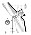
- Fig. 1 illustrates the mounting of a device of the invention in the wall of a steelworks converter.
- a device of the invention in the wall of a steelworks converter.
- a refractory assembly composed of support elements 3 held by the metal carcass 1 and parts 4 delimiting a passage 5 which crosses the wall of the converter.
- the inlet section 6 of passage 5 inside the converter, has the shape of a circular ring segment reproduced in detail view 1a. This same shape is also that of the section of an inlet section 7 of the passage 5.
- the rest of the passage 5, that is to say the outlet section 8, has a circular section, as shown in the view. detail 1b.
- the converter can tilt around an axis, not shown, which is perpendicular to the plane of the drawing.
- Fig. 1 it is shown in the tilted position, that is to say in the position required to ensure the pouring of the molten steel through the passage 5.
- the molten steel 9 reaches the section of entrance to passage 5, while the slag layer 10 has passed this entrance section and is at a higher level.
- the converter is tilted more and more to ensure the complete discharge of the molten steel, then the converter is straightened when all the steel has been discharged and only the slag remains in the converter.
- the particular shape of the entry section of passage 5, recommended by the invention, makes it possible to minimize the penetration of slag in this passage at the times when there is the risk of such penetration: - when the slag layer crosses the inlet section 6 of passage 5, both at tilting and straightening of the converter: the slag is significantly more viscous and lighter than molten steel, and the narrowness of the slit , in the direction of progression of the slag, prevents it from penetrating in a consistent manner into the slot; - During the pouring of the molten steel: the shape of the section of the inlet section 7 of the passage 5 prevents the formation of a vortex and thus prevents any undesirable slag entrainment with the molten steel.
- a device according to another embodiment of the invention.
- the general arrangement is analogous to that of the modality shown in FIG. 1.
- the essential difference lies in the fact that the outlet section 8 of the passage 5 has a constant circular section and that there is provided, at the exit of the passage 5, a converging external nozzle. 11.
- This nozzle is removable, so that it can be easily replaced. It introduces a pressure drop in the trajectory of the molten steel; it is advantageously dimensioned so as to fill the outlet section 8 of the passage 5.
- this outlet section 8 has here a cross section larger than that of the inlet section 7 and the steel flow rate may not not be enough to fill it completely.
- Fig. 3 shows some interesting variants of the shape of the inlet section 6 of the passage 5.
- the inlet section 6 can in particular be single (a) (b) (e) or multiple (c) (d), rectilinear (a ) (c) or curved (b) (d) or of a more complex shape, for example in the shape of "8" (e).
- the basic condition is that this entry section 6 has the form of a slot; in addition, this slot is preferably arranged with its large dimension parallel to the tilting axis, symbolized here in phantom, of the metallurgical container.
Landscapes
- Engineering & Computer Science (AREA)
- Mechanical Engineering (AREA)
- General Engineering & Computer Science (AREA)
- Chemical & Material Sciences (AREA)
- Manufacturing & Machinery (AREA)
- Materials Engineering (AREA)
- Metallurgy (AREA)
- Organic Chemistry (AREA)
- Carbon Steel Or Casting Steel Manufacturing (AREA)
- Furnace Housings, Linings, Walls, And Ceilings (AREA)
- Vertical, Hearth, Or Arc Furnaces (AREA)
Applications Claiming Priority (2)
| Application Number | Priority Date | Filing Date | Title |
|---|---|---|---|
| BE8900119A BE1002808A6 (fr) | 1989-02-06 | 1989-02-06 | Dispositif pour empecher l'entrainement de scorie. |
| BE8900119 | 1989-02-06 |
Publications (1)
| Publication Number | Publication Date |
|---|---|
| EP0382701A1 true EP0382701A1 (de) | 1990-08-16 |
Family
ID=3884003
Family Applications (1)
| Application Number | Title | Priority Date | Filing Date |
|---|---|---|---|
| EP90870016A Withdrawn EP0382701A1 (de) | 1989-02-06 | 1990-02-01 | Vorrichtung um das Mitlaufen von Schlacke zu verhindern |
Country Status (2)
| Country | Link |
|---|---|
| EP (1) | EP0382701A1 (de) |
| BE (1) | BE1002808A6 (de) |
Cited By (5)
| Publication number | Priority date | Publication date | Assignee | Title |
|---|---|---|---|---|
| EP0931839A1 (de) * | 1997-12-24 | 1999-07-28 | SNC Astori et Ferretti O.T.I. Etincelle | Verfahren zur Herstellung von Stahlblöcken mit einem hohen Reinheitsgrad |
| DE102008009368A1 (de) | 2008-02-14 | 2009-08-20 | Cognis Oleochemicals Gmbh | Verfahren zur Herstellung einer organischen Zusammensetzung beinhaltend einen N-Nonylether |
| DE102008009369A1 (de) | 2008-02-14 | 2009-08-20 | Cognis Oleochemicals Gmbh | Verfahren zur Herstellung einer organischen Zusammensetzung beinhaltend einen N-Nonylester |
| DE102008008251A1 (de) | 2008-02-08 | 2009-08-20 | Cognis Oleochemicals Gmbh | Vernetzte Glycerin- oder Oligoglycerinester und deren Verwendung als Additiv in Bohrspülungen |
| CN113122676A (zh) * | 2021-04-19 | 2021-07-16 | 辽宁科技大学 | 一种减轻转炉出钢过程漩涡抑制卷渣的出钢口砖及其制备方法 |
Citations (4)
| Publication number | Priority date | Publication date | Assignee | Title |
|---|---|---|---|---|
| BE412642A (de) * | ||||
| DE1201013B (de) * | 1961-03-18 | 1965-09-16 | Stoecker & Kunz Ges Mit Beschr | Ausguss am Boden einer Giesspfanne fuer fluessige Metalle |
| FR2282962A1 (fr) * | 1974-09-02 | 1976-03-26 | Mannesmann Ag | Buse plongeante de deversement pour installation de coulee continue |
| LU85443A1 (fr) * | 1984-07-02 | 1986-02-12 | Centre Rech Metallurgique | Perfectionnement aux dispositifs d'orifice de coulee de recipients metallurgiques |
-
1989
- 1989-02-06 BE BE8900119A patent/BE1002808A6/fr not_active IP Right Cessation
-
1990
- 1990-02-01 EP EP90870016A patent/EP0382701A1/de not_active Withdrawn
Patent Citations (4)
| Publication number | Priority date | Publication date | Assignee | Title |
|---|---|---|---|---|
| BE412642A (de) * | ||||
| DE1201013B (de) * | 1961-03-18 | 1965-09-16 | Stoecker & Kunz Ges Mit Beschr | Ausguss am Boden einer Giesspfanne fuer fluessige Metalle |
| FR2282962A1 (fr) * | 1974-09-02 | 1976-03-26 | Mannesmann Ag | Buse plongeante de deversement pour installation de coulee continue |
| LU85443A1 (fr) * | 1984-07-02 | 1986-02-12 | Centre Rech Metallurgique | Perfectionnement aux dispositifs d'orifice de coulee de recipients metallurgiques |
Non-Patent Citations (1)
| Title |
|---|
| STAHL UND EISEN, vol. 105, nos 14/15, 1985, pages 765-769; D. SUCKER et al.: "Strömungsuntersuchungen für schmelzmetallurgische Prozesse" * |
Cited By (6)
| Publication number | Priority date | Publication date | Assignee | Title |
|---|---|---|---|---|
| EP0931839A1 (de) * | 1997-12-24 | 1999-07-28 | SNC Astori et Ferretti O.T.I. Etincelle | Verfahren zur Herstellung von Stahlblöcken mit einem hohen Reinheitsgrad |
| DE102008008251A1 (de) | 2008-02-08 | 2009-08-20 | Cognis Oleochemicals Gmbh | Vernetzte Glycerin- oder Oligoglycerinester und deren Verwendung als Additiv in Bohrspülungen |
| US8193125B2 (en) | 2008-02-08 | 2012-06-05 | Emery Oleochemicals Gmbh | Crosslinked glycerol or oligoglycerol esters, and use thereof as an additive in drilling fluids |
| DE102008009368A1 (de) | 2008-02-14 | 2009-08-20 | Cognis Oleochemicals Gmbh | Verfahren zur Herstellung einer organischen Zusammensetzung beinhaltend einen N-Nonylether |
| DE102008009369A1 (de) | 2008-02-14 | 2009-08-20 | Cognis Oleochemicals Gmbh | Verfahren zur Herstellung einer organischen Zusammensetzung beinhaltend einen N-Nonylester |
| CN113122676A (zh) * | 2021-04-19 | 2021-07-16 | 辽宁科技大学 | 一种减轻转炉出钢过程漩涡抑制卷渣的出钢口砖及其制备方法 |
Also Published As
| Publication number | Publication date |
|---|---|
| BE1002808A6 (fr) | 1991-06-18 |
Similar Documents
| Publication | Publication Date | Title |
|---|---|---|
| EP0269180B1 (de) | Vorrichtung zum Giessen eines pastenartigen Metalles | |
| CA1178052A (fr) | Lance de soufflage de gaz oxydant, notamment d'oxygene, pour le traitement des metaux en fusion | |
| EP0094926B1 (de) | Mündung zum Einführen eines Schutzgases in ein Giessrohr | |
| EP2319640A1 (de) | Tauschgiessrohr für Metallschmelze sowie Zusammensetzung dessen mit einer Ausgussdüse | |
| FR2499229A1 (fr) | Dispositif pour boucher le trou de coulee d'un recipient metallurgique | |
| EP0847821A1 (de) | Beschickbehälter für die Aufnahme schmelzflüssigen Metalls, insbesondere Stahlschmelzen | |
| FR2472613A1 (fr) | Procede et appareil de separation de laitier et de coulee d'acier | |
| EP0875319B1 (de) | Zwischengefäss mit mindestens einem Plasmabrenner für die Wiederaufheizung von geschmolzenen Metallen | |
| EP0242347A2 (de) | Vorrichtung zum Giessen einer flüssig-festen Mischung | |
| FR2629101A1 (fr) | Brique pour l'introduction de gaz ou de produits de reaction dans un recipient de coulee metallurgique | |
| EP0213042A2 (de) | Vorrichtung zum Schutz eines flüssigen Giesstrahls gegen Oxydation und/oder Nitrierung | |
| BE1004282A6 (fr) | Dispositif de prechauffage d'une busette de coulee d'un metal en fusion et installation de coulee d'un metal equipee de ce dispositif. | |
| WO1986003147A1 (fr) | Perfectionnements aux poches de coulee pour metal en fusion | |
| FR2659874A1 (fr) | Poussoir a gicleur interne, avec projection laterale, pour pompe de pulverisation a haute pression et a cadence rapide. | |
| EP0327526A1 (de) | Vorrichtung zum Kühlen eines Metalls während des Giessens | |
| EP0528724A1 (de) | Vorrichtung zum automatischen Entschlacken des Giessstrahlschutzrohres beim Stranggiessen | |
| FR2521462A1 (fr) | Dispositif d'amenee du metal dans les lingotieres de coulee continue | |
| EP0171487B1 (de) | Vorrichtung zum Aussenabschluss eines Gefässes für schmelzflüssige Metalle | |
| BE1004078A3 (fr) | Dispositif antivortex adaptable aux trous de coulees de poches de coulee. | |
| EP0302040A2 (de) | Verbesserungen an Pfannen zum Giessen von Metall | |
| EP0495764A1 (de) | Vorwärmvorrichtung für den Ausguss einer Metallgiessanlage | |
| EP0498684B1 (de) | Ausstosseinrichtung für eine Giessschutzrohr-Trageinrichtung in eine Stranggiessvorrichtung | |
| EP0473499B1 (de) | Verfahren und Einrichtung für ein Strahlschutzrohr beim Stranggiessen | |
| FR2670145A1 (fr) | Procede de coulage d'un fluide dans un moule, dispositif et piece pour le procede et le dispositif. | |
| BE1008119A3 (fr) | Dispositif de regulation de debit a fermeture coulissante d'un recipient metallurgique. |
Legal Events
| Date | Code | Title | Description |
|---|---|---|---|
| PUAI | Public reference made under article 153(3) epc to a published international application that has entered the european phase |
Free format text: ORIGINAL CODE: 0009012 |
|
| AK | Designated contracting states |
Kind code of ref document: A1 Designated state(s): AT BE DE FR GB IT LU SE |
|
| 17P | Request for examination filed |
Effective date: 19901224 |
|
| 17Q | First examination report despatched |
Effective date: 19921202 |
|
| STAA | Information on the status of an ep patent application or granted ep patent |
Free format text: STATUS: THE APPLICATION IS DEEMED TO BE WITHDRAWN |
|
| 18D | Application deemed to be withdrawn |
Effective date: 19930414 |