EP0382760B1 - Connector for fluid carrying conduits - Google Patents
Connector for fluid carrying conduits Download PDFInfo
- Publication number
- EP0382760B1 EP0382760B1 EP88908714A EP88908714A EP0382760B1 EP 0382760 B1 EP0382760 B1 EP 0382760B1 EP 88908714 A EP88908714 A EP 88908714A EP 88908714 A EP88908714 A EP 88908714A EP 0382760 B1 EP0382760 B1 EP 0382760B1
- Authority
- EP
- European Patent Office
- Prior art keywords
- parts
- connector
- bores
- lugs
- female
- Prior art date
- Legal status (The legal status is an assumption and is not a legal conclusion. Google has not performed a legal analysis and makes no representation as to the accuracy of the status listed.)
- Expired - Lifetime
Links
- 239000012530 fluid Substances 0.000 title claims abstract description 25
- 230000000295 complement effect Effects 0.000 claims abstract description 4
- 230000007246 mechanism Effects 0.000 claims description 12
- 230000013011 mating Effects 0.000 claims description 5
- 238000000926 separation method Methods 0.000 claims 1
- 238000009434 installation Methods 0.000 abstract description 4
- 238000004519 manufacturing process Methods 0.000 description 11
- 238000007789 sealing Methods 0.000 description 5
- 238000000034 method Methods 0.000 description 4
- 238000013461 design Methods 0.000 description 3
- 238000011161 development Methods 0.000 description 3
- 230000018109 developmental process Effects 0.000 description 3
- 238000012423 maintenance Methods 0.000 description 3
- 238000007667 floating Methods 0.000 description 2
- 238000011068 loading method Methods 0.000 description 2
- XLYOFNOQVPJJNP-UHFFFAOYSA-N water Substances O XLYOFNOQVPJJNP-UHFFFAOYSA-N 0.000 description 2
- 101100194817 Caenorhabditis elegans rig-6 gene Proteins 0.000 description 1
- 238000013459 approach Methods 0.000 description 1
- 230000004888 barrier function Effects 0.000 description 1
- 238000004891 communication Methods 0.000 description 1
- 238000010276 construction Methods 0.000 description 1
- 230000007797 corrosion Effects 0.000 description 1
- 238000005260 corrosion Methods 0.000 description 1
- 230000000994 depressogenic effect Effects 0.000 description 1
- 230000000694 effects Effects 0.000 description 1
- 238000011010 flushing procedure Methods 0.000 description 1
- 238000003780 insertion Methods 0.000 description 1
- 230000037431 insertion Effects 0.000 description 1
- 238000011016 integrity testing Methods 0.000 description 1
- 239000000463 material Substances 0.000 description 1
- 238000012986 modification Methods 0.000 description 1
- 230000004048 modification Effects 0.000 description 1
- 238000012544 monitoring process Methods 0.000 description 1
- 239000003129 oil well Substances 0.000 description 1
- 239000002245 particle Substances 0.000 description 1
- 230000002265 prevention Effects 0.000 description 1
- 230000008569 process Effects 0.000 description 1
- 230000002035 prolonged effect Effects 0.000 description 1
- 239000004576 sand Substances 0.000 description 1
- 239000013535 sea water Substances 0.000 description 1
- 230000035939 shock Effects 0.000 description 1
- 238000011144 upstream manufacturing Methods 0.000 description 1
Images


Classifications
-
- F—MECHANICAL ENGINEERING; LIGHTING; HEATING; WEAPONS; BLASTING
- F16—ENGINEERING ELEMENTS AND UNITS; GENERAL MEASURES FOR PRODUCING AND MAINTAINING EFFECTIVE FUNCTIONING OF MACHINES OR INSTALLATIONS; THERMAL INSULATION IN GENERAL
- F16L—PIPES; JOINTS OR FITTINGS FOR PIPES; SUPPORTS FOR PIPES, CABLES OR PROTECTIVE TUBING; MEANS FOR THERMAL INSULATION IN GENERAL
- F16L37/00—Couplings of the quick-acting type
- F16L37/28—Couplings of the quick-acting type with fluid cut-off means
- F16L37/30—Couplings of the quick-acting type with fluid cut-off means with fluid cut-off means in each of two pipe-end fittings
- F16L37/367—Couplings of the quick-acting type with fluid cut-off means with fluid cut-off means in each of two pipe-end fittings with two gate valves or sliding valves
-
- F—MECHANICAL ENGINEERING; LIGHTING; HEATING; WEAPONS; BLASTING
- F16—ENGINEERING ELEMENTS AND UNITS; GENERAL MEASURES FOR PRODUCING AND MAINTAINING EFFECTIVE FUNCTIONING OF MACHINES OR INSTALLATIONS; THERMAL INSULATION IN GENERAL
- F16L—PIPES; JOINTS OR FITTINGS FOR PIPES; SUPPORTS FOR PIPES, CABLES OR PROTECTIVE TUBING; MEANS FOR THERMAL INSULATION IN GENERAL
- F16L37/00—Couplings of the quick-acting type
- F16L37/002—Couplings of the quick-acting type which can be controlled at a distance
-
- Y—GENERAL TAGGING OF NEW TECHNOLOGICAL DEVELOPMENTS; GENERAL TAGGING OF CROSS-SECTIONAL TECHNOLOGIES SPANNING OVER SEVERAL SECTIONS OF THE IPC; TECHNICAL SUBJECTS COVERED BY FORMER USPC CROSS-REFERENCE ART COLLECTIONS [XRACs] AND DIGESTS
- Y10—TECHNICAL SUBJECTS COVERED BY FORMER USPC
- Y10T—TECHNICAL SUBJECTS COVERED BY FORMER US CLASSIFICATION
- Y10T137/00—Fluid handling
- Y10T137/402—Distribution systems involving geographic features
Definitions
- the present invention relates to a connector for use in connecting and disconnecting fluid carrying conduits such as pipe lines and flow lines for example for use with oil and/or gas, more particularly but not exclusively in subsea locations where for example it is necessary to connect and disconnect such conduits to and from subsea production modules and pipelines.
- QCDC Quadick Connect/Disconnect
- FPV Floating Production Vessel
- US-A-4 460 156 shows a multi bore connector for subsea use in which the bores are aligned in mating surfaces of a plug-and-socket type connector.
- prevention of leakage is achieved by providing certain bores with individual check valves each of which is opened by an operating member depressed by contact between the male and female surfaces.
- This arrangement is prone to leak fluid during connection and disconnection, and is also liable to faulty operation due to debris being present in the area of the mating bores. It is a relatively complex construction with attendant problems of manufacturing cost and risk of mechanical failure.
- the present invention provides a connector for use in connecting and disconnecting fluid carrying conduits, said connector comprising two interconnectable parts, each of which is provided with a plurality of bores, and including obturating means for communicating and discommunicating the bores of one part with respective ones of the bores of the other part when the two parts are interconnected; characterised in that the obturating means is rotatably movable between one position in which the bores of the parts are communicated with each other to permit fluid flow through the bores and thus through the connector, and another position in which the bores of the parts are discommunicated from each other to stop fluid flow through the bores and thus the connector and said parts are disconnectable from each other; and is further characterised by interlock means preventing disconnection of the first and second parts except when the obturating means is in said second position; whereby the first and second parts can be disconnected only when the obturating means discommunicates said bores in said first part from the space exterior to said first part.
- all the connections and valves appertaining to the connection of the existing subsea production modules can be replaced by a single datum, multi-bore connector requiring only one connection operation which can be carried out under diverless conditions by remote control or by suitable underwater robots, remote maintenance systems (RMS), or remotely operated vehicles (ROV).
- RMS remote maintenance systems
- ROV remotely operated vehicles
- connector parts may be provided with any appropriate number of bores to suite individual requirements, in one embodiment it is proposed to provide each part with 10 bores.
- the obturating means comprises a first sleeve on one part and a second sleeve on the other part, each of said sleeves being provided with ports, the sleeves when the two parts are connected being interlinked for rotation, with respective ones of the ports of the sleeves being aligned with each other, such that, when the sleeves are turned together to a first position, the aligned ports align with respective ones of the bores of the two parts to permit fluid flow through the connector and which, when turned to a second position, are disaligned with said respective ones of the bores of the two parts to stop fluid flow through the connector and permit disconnection of the parts.
- the connector includes sealing means which ensure that seals are maintained around the bores of each part during communication and discommunication of the said bores.
- a seal is provided between each bore and the sleeve port aligned therewith during connection of the parts, which seal is of such a shape, for example pear-shaped or tear-drop shaped, so as to encompass also both the bore and the port when in their disaligned position.
- the sealing means of each part also preferably includes at least one annular seal around each of the bores. At least one annular seal is also preferably provided around each of the sleeve ports of one of the parts to provide seals between the aligned ports of the sleeves during connection of the parts.
- the connector includes a latching mechanism for interengaging the two parts and providing a predetermined force which pulls together the said parts during connection thereof.
- one part is provided with cam-shaped projections which engage by rotation during connection of the parts with lugs provided on the other part, the lugs being under tension, by way of for example tension rods, such that engagement of the projections with the lugs pulls the two parts together.
- the connector is of the "plug and socket” type having complementary male and female parts, with the female part, in the case where the connector is used with an offshore production module,being located on the module and the male part being connected to the fluid carrying conduits.
- the outer surface of the sleeve of the male part is inwardly tapered or flared and engages with an outwardly tapered or flared surface on the sleeve of the female part.
- the taper is as slight as possible in order to contain working pressure within the connector and to minimise parting forces between the parts.
- Fixing of the two sleeves with respect to each other to render them fast for turning may be achieved in any convenient manner such as by means of splines or a key in a slot.
- the bore obturating means may be turned in any suitable manner such as mechanically, hydraulically, or electrically.
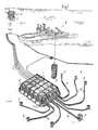
- an offshore oil installation comprises a plurality of subsea production modules 1, which are separately supported within a framework 2 on the seabed 3 and are arranged to collect, via conduits 4, separate and convey oil, gas and water from oil wells 5 to a surface oil rig 6 via conduits 7.
- each module is provided with a connector which is illustrated in Figs. 3 to 9 and generally indicated by the reference 9.
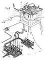
- FIG. 2 another application of the connector 9 is shown, wherein a plurality of subsea production modules 36 are connected to a semi-submersible floating platform 37 by flexible conduits 38.
- Each of the conduits 38 are connected at platform level by one of the connectors 9 to provide quick connection/disconnection of the conduits from the platform if necessary.
- the connector 9 is of the "plug and socket" type which comprises cooperating parts in the form of a female part 10 to be mounted for example to a subsea module and a complementary male part 11 over which the female part 10 fits as shown in Fig. 5, each of the female and male parts being provided with a plurality of bores 12 and 13 respectively with the bores 13 being for connection to fluid carrying conduits such as 4 (Fig.
- the sleeves 14 and 15 are coupled by means (not shown) for turning movement (also by means not shown) between a first position illustrated in the right-hand sides of Figs. 5 and 6, in which the aligned ports 16 and 17 align with the bores 12 and 13 respectively, and a second position (illustrated in the left hand sides of Figs. 5 and 6), in which the ports 16 and 17 are disaligned with the respective bores 12 and 13.
- a number of seals are provided between the bores 12 and sleeve ports 16 of the female part 10 and between the bores 13 and sleeve ports 17 of the male part 11. These seals are located around the bores in each part 10,11 and consist of a primary seal 18 of annular shape to contain internal pressure, a secondary seal 19 also of annular shape to contain external pressure and a pear-shaped envelope seal 20 to contain internal pressure during alignment/disalignment of the ports with the bores.
- Annular seals 21 are also provided between the aligned ports of the two sleeves 14, 15 when the parts 10, 11 are connected.
- Barrier seals 22 are also provided at each end of the sleeves 14, 15 to prevent spillage to the environment of any leakage from the other seals and to prevent ingress of seawater in the event of greater external pressure existing.
- both parts Prior to connection of the two parts 10, 11, both parts are in the "closed” positions, as shown by the left-hand side of Figs. 5 and 6.
- the male part 11, as shown in Fig. 8a is provided with an interlock (not shown) in the form of a locking pin (also not shown) to ensure that the sleeve 15 does not rotate, whilst disconnected, to open the bores 13. In this way, disconnection can be made without spillage of the fluid and the sleeve will be fail safe “locked” or otherwise secured in the bore "closed” position when the two parts are disconnected.
- the female part is lowered over the male part and the two parts are initially held apart by jacking pins 23 to allow filtered water to be flushed through the mating surfaces of the parts to displace any trapped particles of sand, dirt, etc. which may impair the sealing capability.
- a latching mechanism 24 to interengage the parts is operated.
- the mechanism 24 comprises a cam ring 25 provided on the female part 10 which rotates to engage under lugs 26 on the male part 11, whilst also retracting the jacking pins 23 and delatching the interlock in the male part.
- the lugs 26 are connected to tension rods 27, which extend longitudinally through the male part and, when the cam ring engages under the lugs, pull the two parts 10, 11 together.
- the connected parts are thus as shown in Fig. 8b, with the aligned ports 16, 17 out of alignment with the bores 12, 13.
- An alignment and drive key (not shown) is also provided between the two sleeves 14, 15 to ensure that they always rotate together to maintain alignment of the ports 16, 17.
- the sleeves Whilst the parts 10, 11 remain stationary, the sleeves are then rotated, as shown by Fig. 8c, so that the ports 16, 17 move into alignment with the bores 12, 13 to communicate the bores with each other, thereby enabling fluid to flow through the connector.
- the pear-shaped seals 20 ensure that seals are maintained between the bores and sleeve ports of each of the parts.
- Fig. 8d shows the "fully open” position, wherein the bores 12, 13 are intercommunicated by the aligned ports 16, 17, and in this position the annular seals 18 and 21 now contain all the pressure and the pear-shaped seals 20 are not used.
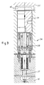
- the latching mechanism is then locked in this position by an interlock 36, shown in an enlarged view in Fig. 9, to prevent disconnection of the two parts 10 and 11 when the sleeves 14 and 15 are in the "open" (live) position.
- the interlock comprises a first spring-loaded pin 37, which is actuated by rotation of the sleeves 14, 15, which in turn actuates a second spring-loaded pin 38, which actuates a shear pin 39 to engage in a hole 40 formed in the cam ring 25. This therefore prevents the cam ring 25 from rotating back to disengage from under the lugs 26.
- Such latching mechanism is suitably strong to withstand module loadings and side current loadings.
- the connector also advantageously includes a guidance and alignment system, which comprises a guide post 28 fixed to the female part 10.
- the post 28 has a conical end 29, which fits into an entry cone in the male part 11 to provide for misalignment, when the guide post is inserted into the central guide passage 30 of the male part.
- an orientation scroll 31 at the other end of the guide post bears on an alignment key 32 which rotates the female part until the key enters its mating keyslot 33. Fine alignment is then achieved by a spigot 34 and an orientation pin 35.
- the bores 13 have axial upstream portions 13a and radial downstream portions 13b disposed at an angle of 90° with respect to the axis of the male part 11.
- All actuation functions such as turning the interlinked sleeves 14 and 15, and latching in both the "open” and “closed” modes are conveniently primarily hydraulic, and such functions preferably have secondary mechanical overrides (not shown) suitable for intervention by remotely operated vehicles (ROVs), or remote maintenance systems(RMS).
- ROVs remotely operated vehicles
- RMS remote maintenance systems
- the male connector part 11 is advantageously suitable for receiving a pressure or corrosion type cap in case of prolonged disconnection.
- the connector described is eminently suitable for subsea use and can be sourced as a proprietry item or in a form modified to suit any particular application.
- the basis of the connector design also enables it to be included in a diverless remotely installable and retrievable modular system.
- cylindrical sleeves 14 and 15 instead of the cylindrical sleeves 14 and 15 two turnable ported discs of which the ports are aligned and disaligned with axially extending bores in the male and female parts may be used.
- the male and female parts 10 and 11 are urged part by the jacking pins 23 after discommunication of the bores has been completed to facilitate disconnection of the two parts 10 and 11.
Landscapes
- Engineering & Computer Science (AREA)
- General Engineering & Computer Science (AREA)
- Mechanical Engineering (AREA)
- Quick-Acting Or Multi-Walled Pipe Joints (AREA)
- Pipeline Systems (AREA)
- Infusion, Injection, And Reservoir Apparatuses (AREA)
- Hydraulic Clutches, Magnetic Clutches, Fluid Clutches, And Fluid Joints (AREA)
- Flanged Joints, Insulating Joints, And Other Joints (AREA)
- Insulated Conductors (AREA)
- Non-Disconnectible Joints And Screw-Threaded Joints (AREA)
- Details Of Connecting Devices For Male And Female Coupling (AREA)
Applications Claiming Priority (3)
| Application Number | Priority Date | Filing Date | Title |
|---|---|---|---|
| GB878722562A GB8722562D0 (en) | 1987-09-25 | 1987-09-25 | Connector for fluid carrying conduits |
| GB8722562 | 1987-09-25 | ||
| PCT/GB1988/000782 WO1989003002A1 (en) | 1987-09-25 | 1988-09-23 | Connector for fluid carrying conduits |
Publications (2)
| Publication Number | Publication Date |
|---|---|
| EP0382760A1 EP0382760A1 (en) | 1990-08-22 |
| EP0382760B1 true EP0382760B1 (en) | 1994-06-01 |
Family
ID=10624353
Family Applications (1)
| Application Number | Title | Priority Date | Filing Date |
|---|---|---|---|
| EP88908714A Expired - Lifetime EP0382760B1 (en) | 1987-09-25 | 1988-09-23 | Connector for fluid carrying conduits |
Country Status (16)
| Country | Link |
|---|---|
| US (1) | US5114117A (da) |
| EP (1) | EP0382760B1 (da) |
| JP (1) | JPH03504263A (da) |
| CN (1) | CN1015819B (da) |
| AT (1) | ATE106518T1 (da) |
| AU (1) | AU612198B2 (da) |
| BR (1) | BR8807716A (da) |
| CA (1) | CA1319166C (da) |
| DE (1) | DE3889919T2 (da) |
| DK (1) | DK76090D0 (da) |
| FI (1) | FI93768C (da) |
| GB (1) | GB8722562D0 (da) |
| MX (1) | MX170014B (da) |
| NO (1) | NO180128C (da) |
| RU (1) | RU2046247C1 (da) |
| WO (1) | WO1989003002A1 (da) |
Families Citing this family (22)
| Publication number | Priority date | Publication date | Assignee | Title |
|---|---|---|---|---|
| GB9123928D0 (en) * | 1991-11-11 | 1992-01-02 | Alpha Thames Eng | Two-part connector for fluid carrying container |
| RU2162185C2 (ru) * | 1998-10-07 | 2001-01-20 | Конструкторское бюро "Арматура" | Устройство автоматической стыковки коммуникаций |
| GB9921373D0 (en) * | 1999-09-10 | 1999-11-10 | Alpha Thames Limited | Modular sea-bed system |
| GB9927137D0 (en) * | 1999-11-16 | 2000-01-12 | Alpha Thames Limited | Two-parter connector for fluid carrying conduits |
| US6755253B2 (en) * | 2001-12-19 | 2004-06-29 | Baker Hughes Incorporated | Pressure control system for a wet connect/disconnect hydraulic control line connector |
| NO320179B1 (no) * | 2002-12-27 | 2005-11-07 | Vetco Aibel As | Undervannssystem |
| US7318479B2 (en) * | 2003-09-23 | 2008-01-15 | Dril-Quip, Inc. | Assembly for connecting a jumper to a subsea structure |
| AU2009201961B2 (en) * | 2007-02-12 | 2011-04-14 | Valkyrie Commissioning Services, Inc | Apparatus and methods for subsea control system testing |
| GB2447645B (en) | 2007-03-16 | 2011-10-19 | Lewis Ltd | A subsea connector incorporating guide and latch means |
| CN101424172B (zh) * | 2007-11-02 | 2012-12-12 | 中国海洋石油总公司 | 防喷器的水下基盘安装导向装置 |
| FR2965559B1 (fr) * | 2010-10-05 | 2012-09-21 | Ksb Sas | Installation de transfert de fluide |
| NO335359B1 (no) * | 2010-10-27 | 2014-12-01 | Roxar Flow Measurement As | Konnektor |
| US8434558B2 (en) * | 2010-11-15 | 2013-05-07 | Baker Hughes Incorporated | System and method for containing borehole fluid |
| NO332311B1 (no) * | 2011-02-09 | 2012-08-27 | Blue Logic As | Anordning ved en ventil |
| US8950497B2 (en) * | 2012-04-23 | 2015-02-10 | Chevron U.S.A. Inc. | Assemblies, systems and methods for installing multiple subsea functional lines |
| US9605772B2 (en) | 2012-05-15 | 2017-03-28 | Schlumberger Technology Corporation | Quick disconnect system |
| US9644443B1 (en) | 2015-12-07 | 2017-05-09 | Fhe Usa Llc | Remotely-operated wellhead pressure control apparatus |
| US10858901B1 (en) | 2018-02-20 | 2020-12-08 | Shazam Rahim | Remotely operated connecting assembly and method |
| US12252949B2 (en) | 2018-03-28 | 2025-03-18 | Fhe Usa Llc | Fluid connection assembly with adapter release |
| US20190301260A1 (en) | 2018-03-28 | 2019-10-03 | Fhe Usa Llc | Remotely operated fluid connection |
| US12049798B2 (en) * | 2020-08-27 | 2024-07-30 | Kellogg Brown & Root Llc | Autonomous subsea tieback enabling platform |
| US20250188812A1 (en) * | 2022-10-21 | 2025-06-12 | Hydril USA Distribution LLC | Multiline riser big bore connector |
Citations (4)
| Publication number | Priority date | Publication date | Assignee | Title |
|---|---|---|---|---|
| US4080025A (en) * | 1976-05-03 | 1978-03-21 | Matra | Automatic connector for underwater connection |
| US4219223A (en) * | 1978-11-09 | 1980-08-26 | Vetco Inc. | Underwater multiple hydraulic line connector |
| WO1986005568A1 (en) * | 1985-03-15 | 1986-09-25 | Jan Axel Svensson | Slide valve and coupler assembly |
| US4648629A (en) * | 1985-05-01 | 1987-03-10 | Vetco Offshore, Inc. | Underwater connector |
Family Cites Families (13)
| Publication number | Priority date | Publication date | Assignee | Title |
|---|---|---|---|---|
| US2753195A (en) * | 1953-07-14 | 1956-07-03 | William D Palmer | Self-sealing coupling |
| US3326579A (en) * | 1964-05-27 | 1967-06-20 | Rockwell Mfg Co | Multiple conduit connection |
| US3551005A (en) * | 1969-04-28 | 1970-12-29 | Westinghouse Electric Corp | Underwater connector |
| US3701549A (en) * | 1970-10-09 | 1972-10-31 | Paul C Koomey | Connector |
| US3820600A (en) * | 1972-06-26 | 1974-06-28 | Stewart & Stevenson Inc Jim | Underwater wellhead connector |
| FR2317586A2 (fr) * | 1975-07-11 | 1977-02-04 | Peugeot & Renault | Raccord rapide pour tuyauterie |
| JPS6016931B2 (ja) * | 1979-10-01 | 1985-04-30 | 帝国臓器製薬株式会社 | 置換安息香酸アミドの製造方法 |
| US4364433A (en) * | 1980-10-15 | 1982-12-21 | Cameron Iron Works, Inc. | Remote connection apparatus |
| US4411454A (en) * | 1980-11-03 | 1983-10-25 | Nl Industries, Inc. | Underwater wellhead connector |
| US4460156A (en) * | 1981-05-01 | 1984-07-17 | Nl Industries, Inc. | Wellhead connector with check valve |
| GB2132728B (en) * | 1981-05-01 | 1985-02-13 | Nl Industries Inc | Wellhead connector with check valve |
| US4408929A (en) * | 1982-01-22 | 1983-10-11 | Baugh Hollis A | Latching system for control lines for pipe-laying barges |
| CA1252384A (en) * | 1985-04-04 | 1989-04-11 | Stephen H. Barkley | Wellhead connecting apparatus |
-
1987
- 1987-09-25 GB GB878722562A patent/GB8722562D0/en active Pending
-
1988
- 1988-09-23 US US07/469,560 patent/US5114117A/en not_active Expired - Lifetime
- 1988-09-23 DE DE3889919T patent/DE3889919T2/de not_active Expired - Fee Related
- 1988-09-23 EP EP88908714A patent/EP0382760B1/en not_active Expired - Lifetime
- 1988-09-23 AU AU25268/88A patent/AU612198B2/en not_active Ceased
- 1988-09-23 BR BR888807716A patent/BR8807716A/pt not_active IP Right Cessation
- 1988-09-23 JP JP63507955A patent/JPH03504263A/ja active Pending
- 1988-09-23 CA CA000578257A patent/CA1319166C/en not_active Expired - Fee Related
- 1988-09-23 AT AT88908714T patent/ATE106518T1/de not_active IP Right Cessation
- 1988-09-23 RU SU884743614A patent/RU2046247C1/ru active
- 1988-09-23 MX MX013152A patent/MX170014B/es unknown
- 1988-09-23 WO PCT/GB1988/000782 patent/WO1989003002A1/en not_active Ceased
- 1988-09-24 CN CN88107580A patent/CN1015819B/zh not_active Expired
-
1990
- 1990-03-23 DK DK076090A patent/DK76090D0/da not_active Application Discontinuation
- 1990-03-23 NO NO901364A patent/NO180128C/no unknown
- 1990-03-26 FI FI901488A patent/FI93768C/fi not_active IP Right Cessation
Patent Citations (4)
| Publication number | Priority date | Publication date | Assignee | Title |
|---|---|---|---|---|
| US4080025A (en) * | 1976-05-03 | 1978-03-21 | Matra | Automatic connector for underwater connection |
| US4219223A (en) * | 1978-11-09 | 1980-08-26 | Vetco Inc. | Underwater multiple hydraulic line connector |
| WO1986005568A1 (en) * | 1985-03-15 | 1986-09-25 | Jan Axel Svensson | Slide valve and coupler assembly |
| US4648629A (en) * | 1985-05-01 | 1987-03-10 | Vetco Offshore, Inc. | Underwater connector |
Also Published As
| Publication number | Publication date |
|---|---|
| DK76090A (da) | 1990-03-23 |
| WO1989003002A1 (en) | 1989-04-06 |
| FI93768C (fi) | 1995-05-26 |
| CA1319166C (en) | 1993-06-15 |
| NO180128B (no) | 1996-11-11 |
| RU2046247C1 (ru) | 1995-10-20 |
| FI901488A0 (fi) | 1990-03-26 |
| GB8722562D0 (en) | 1987-11-04 |
| JPH03504263A (ja) | 1991-09-19 |
| EP0382760A1 (en) | 1990-08-22 |
| BR8807716A (pt) | 1990-07-24 |
| NO180128C (no) | 1997-02-19 |
| NO901364D0 (no) | 1990-03-23 |
| MX170014B (es) | 1993-08-04 |
| DE3889919D1 (de) | 1994-07-07 |
| FI93768B (fi) | 1995-02-15 |
| CN1036447A (zh) | 1989-10-18 |
| NO901364L (no) | 1990-03-23 |
| DE3889919T2 (de) | 1995-01-05 |
| DK76090D0 (da) | 1990-03-23 |
| US5114117A (en) | 1992-05-19 |
| ATE106518T1 (de) | 1994-06-15 |
| CN1015819B (zh) | 1992-03-11 |
| AU2526888A (en) | 1989-04-18 |
| AU612198B2 (en) | 1991-07-04 |
Similar Documents
| Publication | Publication Date | Title |
|---|---|---|
| US5114117A (en) | Connector for fluid carrying conduits | |
| US4768538A (en) | Radial seal hydraulic coupler | |
| US3732923A (en) | Remote underwater flowline connection | |
| US7040406B2 (en) | Subsea riser disconnect and method | |
| GB2296301A (en) | Lateral fluid or electrical coupling | |
| EP1282757A1 (en) | Subsea riser disconnect and method | |
| CA1250226A (en) | Subsea flowline connector | |
| US5494110A (en) | Two-part connector for fluid carrying conduits | |
| US6050544A (en) | Valve coupling device forming metal-to-metal seal | |
| US20020109352A1 (en) | Junction plate assembly for undersea hydraulic couplings | |
| EP3779115B1 (en) | Tool coupler with threaded connection for top drive | |
| US7083201B2 (en) | Junction plate assembly for undersea hydraulic couplings | |
| AU8466998A (en) | Connector for fluid flow lines | |
| US20240141768A1 (en) | Dynamic manifold locking system | |
| EP4127390B1 (en) | Single line quick connector (sqc), a system comprising the single line quick connector and method of operating | |
| EP2476860B1 (en) | Filtration systems for chemical fluids | |
| CN108625798A (zh) | 一种深水隔水管应急脱接器 | |
| AU7829001A (en) | Junction plate assembly for undersea hydraulic couplings | |
| JPS5911799B2 (ja) | 継手 |
Legal Events
| Date | Code | Title | Description |
|---|---|---|---|
| PUAI | Public reference made under article 153(3) epc to a published international application that has entered the european phase |
Free format text: ORIGINAL CODE: 0009012 |
|
| 17P | Request for examination filed |
Effective date: 19900321 |
|
| AK | Designated contracting states |
Kind code of ref document: A1 Designated state(s): AT BE CH DE FR GB IT LI LU NL SE |
|
| RAP1 | Party data changed (applicant data changed or rights of an application transferred) |
Owner name: SCOTTISH DEVELOPMENT AGENCY |
|
| 17Q | First examination report despatched |
Effective date: 19920213 |
|
| RAP1 | Party data changed (applicant data changed or rights of an application transferred) |
Owner name: SCOTTISH ENTERPRISE |
|
| GRAA | (expected) grant |
Free format text: ORIGINAL CODE: 0009210 |
|
| AK | Designated contracting states |
Kind code of ref document: B1 Designated state(s): AT BE CH DE FR GB IT LI LU NL SE |
|
| PG25 | Lapsed in a contracting state [announced via postgrant information from national office to epo] |
Ref country code: LI Effective date: 19940601 Ref country code: AT Effective date: 19940601 Ref country code: CH Effective date: 19940601 |
|
| REF | Corresponds to: |
Ref document number: 106518 Country of ref document: AT Date of ref document: 19940615 Kind code of ref document: T |
|
| REF | Corresponds to: |
Ref document number: 3889919 Country of ref document: DE Date of ref document: 19940707 |
|
| ITF | It: translation for a ep patent filed | ||
| REG | Reference to a national code |
Ref country code: CH Ref legal event code: PL |
|
| PG25 | Lapsed in a contracting state [announced via postgrant information from national office to epo] |
Ref country code: LU Free format text: LAPSE BECAUSE OF NON-PAYMENT OF DUE FEES Effective date: 19940930 |
|
| ET | Fr: translation filed | ||
| EAL | Se: european patent in force in sweden |
Ref document number: 88908714.4 |
|
| PLBE | No opposition filed within time limit |
Free format text: ORIGINAL CODE: 0009261 |
|
| STAA | Information on the status of an ep patent application or granted ep patent |
Free format text: STATUS: NO OPPOSITION FILED WITHIN TIME LIMIT |
|
| 26N | No opposition filed | ||
| PGFP | Annual fee paid to national office [announced via postgrant information from national office to epo] |
Ref country code: FR Payment date: 19970808 Year of fee payment: 10 |
|
| PGFP | Annual fee paid to national office [announced via postgrant information from national office to epo] |
Ref country code: DE Payment date: 19970814 Year of fee payment: 10 Ref country code: NL Payment date: 19970814 Year of fee payment: 10 Ref country code: SE Payment date: 19970814 Year of fee payment: 10 |
|
| PGFP | Annual fee paid to national office [announced via postgrant information from national office to epo] |
Ref country code: BE Payment date: 19970911 Year of fee payment: 10 |
|
| PG25 | Lapsed in a contracting state [announced via postgrant information from national office to epo] |
Ref country code: SE Free format text: LAPSE BECAUSE OF NON-PAYMENT OF DUE FEES Effective date: 19980924 |
|
| PG25 | Lapsed in a contracting state [announced via postgrant information from national office to epo] |
Ref country code: BE Free format text: LAPSE BECAUSE OF NON-PAYMENT OF DUE FEES Effective date: 19980930 |
|
| BERE | Be: lapsed |
Owner name: SCOTTISH ENTERPRISE Effective date: 19980930 |
|
| PG25 | Lapsed in a contracting state [announced via postgrant information from national office to epo] |
Ref country code: NL Free format text: LAPSE BECAUSE OF NON-PAYMENT OF DUE FEES Effective date: 19990401 |
|
| EUG | Se: european patent has lapsed |
Ref document number: 88908714.4 |
|
| PG25 | Lapsed in a contracting state [announced via postgrant information from national office to epo] |
Ref country code: FR Free format text: LAPSE BECAUSE OF NON-PAYMENT OF DUE FEES Effective date: 19990531 |
|
| NLV4 | Nl: lapsed or anulled due to non-payment of the annual fee |
Effective date: 19990401 |
|
| PG25 | Lapsed in a contracting state [announced via postgrant information from national office to epo] |
Ref country code: DE Free format text: LAPSE BECAUSE OF NON-PAYMENT OF DUE FEES Effective date: 19990701 |
|
| REG | Reference to a national code |
Ref country code: FR Ref legal event code: ST |
|
| REG | Reference to a national code |
Ref country code: GB Ref legal event code: 732E |
|
| REG | Reference to a national code |
Ref country code: GB Ref legal event code: IF02 |
|
| PGFP | Annual fee paid to national office [announced via postgrant information from national office to epo] |
Ref country code: GB Payment date: 20050825 Year of fee payment: 18 |
|
| PG25 | Lapsed in a contracting state [announced via postgrant information from national office to epo] |
Ref country code: IT Free format text: LAPSE BECAUSE OF NON-PAYMENT OF DUE FEES;WARNING: LAPSES OF ITALIAN PATENTS WITH EFFECTIVE DATE BEFORE 2007 MAY HAVE OCCURRED AT ANY TIME BEFORE 2007. THE CORRECT EFFECTIVE DATE MAY BE DIFFERENT FROM THE ONE RECORDED. Effective date: 20050923 |
|
| GBPC | Gb: european patent ceased through non-payment of renewal fee |
Effective date: 20060923 |
|
| PG25 | Lapsed in a contracting state [announced via postgrant information from national office to epo] |
Ref country code: GB Free format text: LAPSE BECAUSE OF NON-PAYMENT OF DUE FEES Effective date: 20060923 |