EP0382888A2 - Spritzgiessystem mit einer Verschlussnadel mit einem gerippten isolierenden Teil - Google Patents
Spritzgiessystem mit einer Verschlussnadel mit einem gerippten isolierenden Teil Download PDFInfo
- Publication number
- EP0382888A2 EP0382888A2 EP89114744A EP89114744A EP0382888A2 EP 0382888 A2 EP0382888 A2 EP 0382888A2 EP 89114744 A EP89114744 A EP 89114744A EP 89114744 A EP89114744 A EP 89114744A EP 0382888 A2 EP0382888 A2 EP 0382888A2
- Authority
- EP
- European Patent Office
- Prior art keywords
- valve member
- tip end
- injection molding
- molding system
- insulative
- Prior art date
- Legal status (The legal status is an assumption and is not a legal conclusion. Google has not performed a legal analysis and makes no representation as to the accuracy of the status listed.)
- Granted
Links
- 238000001746 injection moulding Methods 0.000 title claims abstract description 13
- 229910000831 Steel Inorganic materials 0.000 claims abstract description 4
- 239000010959 steel Substances 0.000 claims abstract description 4
- 239000000155 melt Substances 0.000 claims description 6
- 229910052751 metal Inorganic materials 0.000 claims description 4
- 239000002184 metal Substances 0.000 claims description 4
- 239000004020 conductor Substances 0.000 claims 2
- RYGMFSIKBFXOCR-UHFFFAOYSA-N Copper Chemical compound [Cu] RYGMFSIKBFXOCR-UHFFFAOYSA-N 0.000 claims 1
- 229910052802 copper Inorganic materials 0.000 claims 1
- 239000010949 copper Substances 0.000 claims 1
- 238000001816 cooling Methods 0.000 abstract description 4
- DMFGNRRURHSENX-UHFFFAOYSA-N beryllium copper Chemical compound [Be].[Cu] DMFGNRRURHSENX-UHFFFAOYSA-N 0.000 abstract description 3
- 230000004888 barrier function Effects 0.000 abstract description 2
- 238000002347 injection Methods 0.000 description 4
- 239000007924 injection Substances 0.000 description 4
- 238000000465 moulding Methods 0.000 description 3
- 229910000881 Cu alloy Inorganic materials 0.000 description 1
- 229910052790 beryllium Inorganic materials 0.000 description 1
- ATBAMAFKBVZNFJ-UHFFFAOYSA-N beryllium atom Chemical compound [Be] ATBAMAFKBVZNFJ-UHFFFAOYSA-N 0.000 description 1
- 238000010276 construction Methods 0.000 description 1
- 239000000498 cooling water Substances 0.000 description 1
- 230000001419 dependent effect Effects 0.000 description 1
- 230000003116 impacting effect Effects 0.000 description 1
- 239000000463 material Substances 0.000 description 1
- 238000012986 modification Methods 0.000 description 1
- 230000004048 modification Effects 0.000 description 1
- 238000005086 pumping Methods 0.000 description 1
- 238000007789 sealing Methods 0.000 description 1
Images

Classifications
-
- B—PERFORMING OPERATIONS; TRANSPORTING
- B29—WORKING OF PLASTICS; WORKING OF SUBSTANCES IN A PLASTIC STATE IN GENERAL
- B29C—SHAPING OR JOINING OF PLASTICS; SHAPING OF MATERIAL IN A PLASTIC STATE, NOT OTHERWISE PROVIDED FOR; AFTER-TREATMENT OF THE SHAPED PRODUCTS, e.g. REPAIRING
- B29C45/00—Injection moulding, i.e. forcing the required volume of moulding material through a nozzle into a closed mould; Apparatus therefor
- B29C45/17—Component parts, details or accessories; Auxiliary operations
- B29C45/26—Moulds
- B29C45/27—Sprue channels ; Runner channels or runner nozzles
- B29C45/28—Closure devices therefor
- B29C45/2806—Closure devices therefor consisting of needle valve systems
-
- B—PERFORMING OPERATIONS; TRANSPORTING
- B29—WORKING OF PLASTICS; WORKING OF SUBSTANCES IN A PLASTIC STATE IN GENERAL
- B29C—SHAPING OR JOINING OF PLASTICS; SHAPING OF MATERIAL IN A PLASTIC STATE, NOT OTHERWISE PROVIDED FOR; AFTER-TREATMENT OF THE SHAPED PRODUCTS, e.g. REPAIRING
- B29C45/00—Injection moulding, i.e. forcing the required volume of moulding material through a nozzle into a closed mould; Apparatus therefor
- B29C45/17—Component parts, details or accessories; Auxiliary operations
- B29C45/26—Moulds
- B29C45/27—Sprue channels ; Runner channels or runner nozzles
- B29C2045/2761—Seals between nozzle and mould or gate
-
- B—PERFORMING OPERATIONS; TRANSPORTING
- B29—WORKING OF PLASTICS; WORKING OF SUBSTANCES IN A PLASTIC STATE IN GENERAL
- B29C—SHAPING OR JOINING OF PLASTICS; SHAPING OF MATERIAL IN A PLASTIC STATE, NOT OTHERWISE PROVIDED FOR; AFTER-TREATMENT OF THE SHAPED PRODUCTS, e.g. REPAIRING
- B29C45/00—Injection moulding, i.e. forcing the required volume of moulding material through a nozzle into a closed mould; Apparatus therefor
- B29C45/17—Component parts, details or accessories; Auxiliary operations
- B29C45/26—Moulds
- B29C45/27—Sprue channels ; Runner channels or runner nozzles
- B29C45/28—Closure devices therefor
- B29C45/2806—Closure devices therefor consisting of needle valve systems
- B29C2045/2858—Materials or coatings therefor
Definitions
- This invention relates generally to injection molding and more particularly to a valve gated system having a valve member having a conductive portion at the forward tip end supported by a ribbed insulative portion.
- insulative air spaces are well known in the injection molding field. For instance, insulative air spaces are normally provided between a heated nozzle and the surrounding cooled cavity plate. Furthermore, the use of an air space adjacent a conductive plug in a valve pin is disclosed in the applicant's U.S. patent number 4,521,179 which issued June 4, 1985 relating to core ring gate molding. However, in that application there is no concern or requirement for high structural strength because the valve member or pin is not subject to continual impacting when it closes.
- valve pin construction with an insulative portion which provides additional structural strength to the conductive portion.
- the invention provides a valve gated hot runner injection molding system having a heated nozzle seated in a well in a cavity plate, the nozzle having a central bore extending therethrough to receive an elongated valve member with a forward tip end and a rear end and to provide a melt passage which extends in the central bore around at least at forward portion of the valve member to convey melt to a gate extending through the cavity plate to a cavity, and valve member actuating means to reciprocate the valve member longitudinally between a retracted open position and a forward closed position in which the tip end of the valve member is seated in the gate, the improvement wherein the valve member comprises an integral insulative portion between a relatively long steel main portion extending from the rear end and a relatively short conductive portion adjacent the forward tip end, the conductive portion including a highly conductive metal, the insulative portion including at least one longitudinal rib positioned to support the conductive metal of the conductive portion.
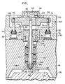
- FIG. 1 shows a nozzle 10 seated in a well 12 in a cavity plate 14.
- the nozzle 10 has a central bore 16 which is aligned with a gate 18 which extends through the cavity plate 14 to a cavity 20.
- the nozzle 10 is accurately located in this position by an insulating flange 22 which seats against a circumferential shoulder 24 and by a nozzle seal insert 26.
- the nozzle seal insert 26 which is screwed into the forward end 28 of the nozzle 10 has a cylindrical nose portion 30 which is received in a seat 32 around the gate 18 and a tapered bore 34 which is in alignment with and extends from the central bore 16 of the nozzle 10 to the gate 18.
- Electric plate heaters 36 as described in the applicant's Canadian patent application serial no.
- a manifold 42 is secured to the rear end 44 of the nozzle 10 by bolts 46.
- the manifold 42 and the nozzle 10 are held in place by a locating collar 48 which is fastened to the back plate 50 by bolts 52.
- the back plate 50 is, in turn, mounted to the cavity plate 14 by bolts which are not shown.
- the manifold 42 is heated by electric plate heaters 54 attached to opposite sides 56.
- the heated manifold 42 is thermally separated from the surrounding cooled back plate 50 by an insulative air space 58, with only minimum contact with the locating collar 48.
- the manifold 42 has a transverse opening 60 which is large enough to receive a movable actuating yoke 62 therethrough.
- the yoke 62 is fastened by screw 63 to the rear end 64 of an elongated valve member 66 which is received in the central bore 16 of the nozzle 10.
- the outer ends 68 of the yoke 62 are each connected by a screw 70 to a rod 72 extending from a hydraulically actuated piston 74 in a cylinder 76 seated in the back plate 50.
- a high pressure seal 78 extends around each piston rod 72 to prevent leakage.
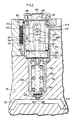
- the pair of pistons 74 are activated in unison according to a predetermined cycle to reciprocate the yoke 62 and the valve member 66 between the retracted open position shown in Figure 1 and the forward closed position shown in Figure 2 in which the forward tip end 80 of the valve member is seated in the gate 18.
- a melt passage 82 extends to convey pressurized melt from a central inlet 84 at the rear end 86 of the manifold 42 to the gate 18.
- the passage 82 splits into two branches 88 which extend around the opening 60 through the manifold 42 in which the yoke 62 reciprocates and join a space 90 in the central bore 16 around the valve member 66.
- the melt then flows through the gate 18 to fill cavity 20.
- a sealing sleeve 92 is seated around the valve member 66 in the central bore 16 at the rear end 44 of the nozzle 10 to prevent leakage of the pressurized melt from the space 90 as the valve member 66 reciprocates.
- the valve member 66 has an integral insulative portion 94 extending between a relatively long main portion 96 which extends from the rear end 64 and a relatively short conductive portion 98 adjacent the forward tip end 80.
- the valve member 66 is made from a steel rod 100 which is machined from the forward end 80 to form a number of radially extending longitudinal ribs 102 surrounded by an outer sleeve portion 104.
- the outer sleeve portion 104 extends to the forward end 80 to form a central seat 106 between the ribs 102 and the forward end 80.
- a cylindrical plug 108 of beryllium copper alloy is then integrally brazed or welded in place in the seat 106 to form the forward tip end 80 of the valve member 66.
- the insulative portion 94 has a number of insulative air spaces 110 between the outer sleeve portion 104 and the ribs 102, but the ribs 102 provide structual support for the relatively weak beryllium cope portion 108 to withstand the continually repeated impact forces when it closes. This is particularly critical for large volume applications wherein relatively large diameter valve members are required.
- the system is assembled as shown and electrical power is applied to the leads 112,114 to the plate heaters 36,54 to heat the nozzle 10 and the manifold 42 to a predetermined operating temperature.
- Pressurized melt from a molding machine (not shown) is injected into the melt passage 82 through the central inlet 84 according to a predetermined cycle. Hydraulic pressure to the cylinders 76 is also controlled according to the cycle to position the valve member 66 in the retracted open position when the injection melt pressure is applied.
- the melt flows through the space 90 around each valve member 66 and through the gate 18 to fill the cavity 20.
- Injection pressure is then held momentarily to pack and then the pistons 74 drive the yoke 62 and the valve member 66 to the forward closed position in which the tip end 80 of the valve member 66 is seated in the gate 18.
- Injection pressure is then released and after a short cooling period, the mold is opened along the parting line 116 to eject the molded product.
- the mold is closed and hydraulic pressure is reapplied to the cylinders 76 to withdraw the valve members 66 to the open position and injection pressure is reapplied to refill the cavities 20. This cycle is repeated continuously with a frequency dependent upon the size of cavity and type of material being molded. Each time the valve member 66 is driven forward to the closed position there is an impact load on the forward tip end 80.
- the configuration of the insulative portion 94 of the valve member 66 provides the ribs 102 which support the beryllium copper plug 108 to prevent it failing under this continual impact loading.
- the air spaces 110 between the ribs 102 provide a thermal barrier to heat transfer along the valve member 66 from the main portion 96 to the conductive portion 98 at the tip end 80.
- the conductive portion 98 provides for more rapid cooling of the conductive portion when it contacts the gate 18 in the cooled cavity plate 14 in the forward closed position. This combination of the insulative portion 94 and the conductive portion 98 results in a more rapid decrease in temperature of the tip end 80 which in turn reduces sticking when the mold opens. This allows the cycle time to be reduced, without an unacceptable loss in structual strength of the valve member 66.
Landscapes
- Engineering & Computer Science (AREA)
- Manufacturing & Machinery (AREA)
- Mechanical Engineering (AREA)
- Moulds For Moulding Plastics Or The Like (AREA)
- Injection Moulding Of Plastics Or The Like (AREA)
Applications Claiming Priority (2)
| Application Number | Priority Date | Filing Date | Title |
|---|---|---|---|
| CA591009 | 1989-02-14 | ||
| CA000591009A CA1292848C (en) | 1989-02-14 | 1989-02-14 | Injection molding system having a valve member with a ribbed insulative portion |
Publications (3)
| Publication Number | Publication Date |
|---|---|
| EP0382888A2 true EP0382888A2 (de) | 1990-08-22 |
| EP0382888A3 EP0382888A3 (de) | 1991-07-10 |
| EP0382888B1 EP0382888B1 (de) | 1995-04-19 |
Family
ID=4139619
Family Applications (1)
| Application Number | Title | Priority Date | Filing Date |
|---|---|---|---|
| EP89114744A Expired - Lifetime EP0382888B1 (de) | 1989-02-14 | 1989-08-09 | Spritzgiessystem mit einer Verschlussnadel mit einem gerippten isolierenden Teil |
Country Status (8)
| Country | Link |
|---|---|
| US (1) | US4923387A (de) |
| EP (1) | EP0382888B1 (de) |
| JP (1) | JP2738566B2 (de) |
| CN (1) | CN1018901B (de) |
| AT (1) | ATE121343T1 (de) |
| CA (1) | CA1292848C (de) |
| DE (2) | DE3926357A1 (de) |
| ES (1) | ES2071631T3 (de) |
Cited By (2)
| Publication number | Priority date | Publication date | Assignee | Title |
|---|---|---|---|---|
| EP0587027A1 (de) * | 1992-09-09 | 1994-03-16 | Mitsubishi Gas Chemical Company, Inc. | Antriebsvorrichtung zum Antrieb eines beweglichen Teiles in einer Formvorrichtung für Kunststoff |
| EP3025842A1 (de) * | 2014-11-28 | 2016-06-01 | RICO Elastomere Projecting GmbH | Spritzgussdüse für ein spritzgusswerkzeug |
Families Citing this family (31)
| Publication number | Priority date | Publication date | Assignee | Title |
|---|---|---|---|---|
| CA1317918C (en) * | 1988-06-24 | 1993-05-18 | Katutada Shirai | Motor vehicle headlight including device for measuring deviation and adjusting direction of orientation of headlight beam |
| US5078589A (en) * | 1990-06-15 | 1992-01-07 | Osuna Diaz J M | Multicavity injection molding apparatus having precision adjustment and shut off of injection flow to individual mold cavities |
| IT1248888B (it) * | 1991-06-28 | 1995-01-30 | Acrilux Spa | Ugello di iniezione per uno stampo |
| DE19503073A1 (de) * | 1995-02-01 | 1996-08-08 | Peter Ott | Spritzdüse |
| US5635227A (en) * | 1995-06-07 | 1997-06-03 | R & D Tool And Engineering, Inc. | Replaceable air cylinder unit and valve gate for injection molding machines |
| DE19601102C2 (de) * | 1996-01-13 | 1999-04-15 | Psg Plastic Service Gmbh | Heißkanalsystem |
| US5820900A (en) * | 1996-08-21 | 1998-10-13 | Mcgrevy; Alan N. | Heating device for an injection mold apparatus |
| US5855934A (en) * | 1997-05-27 | 1999-01-05 | Tradesco Mold Limited | Valve pin actuator |
| DE19836506A1 (de) * | 1998-08-12 | 2000-03-02 | Bayer Ag | Heißkanaldüse mit Verschlußnadel aus Keramik |
| US6419476B1 (en) | 1998-08-25 | 2002-07-16 | Joseph P. Ouellette | Thermally insulated runner manifold and injection nozzle construction for plastic molding apparatus |
| US6135757A (en) * | 1998-10-16 | 2000-10-24 | Husky Injection Systems Ltd. | Valve gated injection molding system |
| US6755641B1 (en) * | 2000-09-01 | 2004-06-29 | Mold-Masters Limited | Stack injection molding apparatus with separately actuated arrays of valve gates |
| JP4350520B2 (ja) | 2002-01-09 | 2009-10-21 | モールド−マスターズ (2007) リミテッド | 金型キャビティ内の溶融材料の温度を計測するための方法及び装置 |
| US7014455B2 (en) * | 2002-03-14 | 2006-03-21 | Mold-Masters Limited | Valve-gated injection molding system with side-mounted actuator |
| US7510392B2 (en) * | 2002-11-06 | 2009-03-31 | Mold-Masters (2007) Limited | Injection nozzle with a removable heater device having one or more heating elements |
| JP2005132075A (ja) * | 2002-11-06 | 2005-05-26 | Mold Masters Ltd | 板状ヒータを備えた射出ノズル |
| US7131833B2 (en) * | 2002-11-21 | 2006-11-07 | Mold-Masters Ltd. | Nozzle with thermally conductive device |
| CA2452894A1 (en) * | 2002-12-13 | 2004-06-13 | Mold-Masters Limited | Nozzle and method for making a nozzle with a removable and replaceable heating device |
| US20050074514A1 (en) * | 2003-10-02 | 2005-04-07 | Anderson Oliver B. | Zero cycle molding systems, methods and apparatuses for manufacturing dosage forms |
| US7210922B1 (en) * | 2004-11-18 | 2007-05-01 | Tech Mold, Inc. | Valve pin operating mechanism |
| JP2009534237A (ja) * | 2006-04-24 | 2009-09-24 | ボラスティック、カンパニー、リミテッド | 射出成形ノズル及びこのノズル用の先端部 |
| US20070264435A1 (en) * | 2006-05-10 | 2007-11-15 | Kenrick Venett | Material processing system through an injection nozzle |
| US7553150B2 (en) * | 2006-06-19 | 2009-06-30 | Mold-Masters (2007) Limited | Valve-pin actuating device for a hot runner apparatus |
| US20080206391A1 (en) * | 2007-02-27 | 2008-08-28 | Husky Injection Molding Systems Ltd. | Injection Molding Nozzle Assembly with Composite Nozzle Tip |
| IT1397284B1 (it) * | 2009-11-30 | 2013-01-04 | Inglass Spa | Iniettore per apparecchiature di stampaggio ad iniezione di materie plastiche. |
| CN102770257B (zh) * | 2010-03-25 | 2015-11-25 | 圣万提注塑工业有限公司 | 致动器安装系统 |
| CN101973108A (zh) * | 2010-08-25 | 2011-02-16 | 青岛海信模具有限公司 | 一种能够提高成型产品外观质量的模具结构 |
| JP5770930B2 (ja) * | 2011-04-26 | 2015-08-26 | ハスキー インジェクション モールディング システムズ リミテッドHusky Injection Molding Systems Limited | 低減された軸方向の傾斜に対して構成されたノズルチップアセンブリを含む金型ツールシステム |
| KR101155327B1 (ko) | 2012-02-28 | 2012-06-19 | 이재응 | 멀티실린더 싱글밸브 노즐장치 |
| CN103331869B (zh) * | 2013-06-09 | 2016-09-28 | 林作钱 | 一种用于注射器部件的精确定位的热浇口喷嘴结构 |
| DE102016106745A1 (de) | 2016-04-12 | 2017-10-12 | Günther Heisskanaltechnik Gmbh | Führungsbuchse für eine Spritzgießvorrichtung |
Family Cites Families (6)
| Publication number | Priority date | Publication date | Assignee | Title |
|---|---|---|---|---|
| CA1167222A (en) * | 1981-07-15 | 1984-05-15 | Jobst U. Gellert | Valve pin and method of manufacture |
| CA1193817A (en) * | 1983-02-24 | 1985-09-24 | Jobst U. Gellert | Injection molding core ring gate system |
| US4657496A (en) * | 1984-06-04 | 1987-04-14 | Gifu Husky Co., Ltd. | Hot-runner mold for injection molding |
| US4717324A (en) * | 1986-05-12 | 1988-01-05 | Husky Injection Molding Systems, Inc. | Coinjection of hollow articles and preforms |
| CA1252969A (en) * | 1986-10-15 | 1989-04-25 | Henry J. Rozema | Sealing and retaining bushing for injection molding |
| CA1261579A (en) * | 1987-03-19 | 1989-09-26 | Mold-Masters Limited | Replaceable rocker arm assembly for injection molding system |
-
1989
- 1989-02-14 CA CA000591009A patent/CA1292848C/en not_active Expired - Lifetime
- 1989-02-27 US US07/315,487 patent/US4923387A/en not_active Expired - Lifetime
- 1989-08-09 DE DE3926357A patent/DE3926357A1/de not_active Withdrawn
- 1989-08-09 AT AT89114744T patent/ATE121343T1/de not_active IP Right Cessation
- 1989-08-09 DE DE68922294T patent/DE68922294T2/de not_active Expired - Fee Related
- 1989-08-09 EP EP89114744A patent/EP0382888B1/de not_active Expired - Lifetime
- 1989-08-09 ES ES89114744T patent/ES2071631T3/es not_active Expired - Lifetime
- 1989-08-28 JP JP1221379A patent/JP2738566B2/ja not_active Expired - Lifetime
-
1990
- 1990-02-09 CN CN90100568.1A patent/CN1018901B/zh not_active Expired
Cited By (2)
| Publication number | Priority date | Publication date | Assignee | Title |
|---|---|---|---|---|
| EP0587027A1 (de) * | 1992-09-09 | 1994-03-16 | Mitsubishi Gas Chemical Company, Inc. | Antriebsvorrichtung zum Antrieb eines beweglichen Teiles in einer Formvorrichtung für Kunststoff |
| EP3025842A1 (de) * | 2014-11-28 | 2016-06-01 | RICO Elastomere Projecting GmbH | Spritzgussdüse für ein spritzgusswerkzeug |
Also Published As
| Publication number | Publication date |
|---|---|
| DE68922294D1 (de) | 1995-05-24 |
| ATE121343T1 (de) | 1995-05-15 |
| CN1044918A (zh) | 1990-08-29 |
| CN1018901B (zh) | 1992-11-04 |
| JP2738566B2 (ja) | 1998-04-08 |
| EP0382888A3 (de) | 1991-07-10 |
| DE68922294T2 (de) | 1995-08-24 |
| CA1292848C (en) | 1991-12-10 |
| JPH02276614A (ja) | 1990-11-13 |
| DE3926357A1 (de) | 1990-08-16 |
| ES2071631T3 (es) | 1995-07-01 |
| EP0382888B1 (de) | 1995-04-19 |
| US4923387A (en) | 1990-05-08 |
Similar Documents
| Publication | Publication Date | Title |
|---|---|---|
| US4923387A (en) | Injection molding system having a valve member with a ribbed insulative portion | |
| EP0873841B1 (de) | Spritzgiessdüse mit einteiligem Einspritzöffnungseinsatz zum Halten eines zylindrischen Ventils | |
| EP0385175B1 (de) | Spritzgusseinrichtung mit Gasdurchfluss durch die Ventilöffnung | |
| US5049062A (en) | Injection molding system having spring biased nozzles | |
| CA1292849C (en) | Pneumatic actuating mechanism for injection molding | |
| EP0614743B1 (de) | Einsatz für Spritzgiessdüse mit Ventilzentrierblättern | |
| US4521179A (en) | Injection molding core ring gate system | |
| US4530654A (en) | Injection molding peripheral opening core ring gate | |
| EP0200048B1 (de) | Als Ventil ausgebildeter Torpedo | |
| EP0405007A2 (de) | Spritzgiesssystem mit einer Buchse mit doppelter Zufuhr, montiert im Verteilerkanal | |
| EP0668141A1 (de) | Abdichtungsbüchse für Ventil im Spritzgiessen mit dünnem Kragenteil | |
| EP0849061A1 (de) | Spritzgiessvorrichtung mit Einsatz durch den Verteiler zu einer Düse | |
| EP0264724A2 (de) | Mechanismus zum Spritzgiessen mit Verschlussdüsen-Anguss mit einem elastischen Haltering | |
| US5061174A (en) | Injection molding apparatus having separate heating element in the cavity forming insert | |
| EP0374549B1 (de) | Spritzgiessvorrichtung mit durch Fluidum gekühlten Einsätzen | |
| US4786246A (en) | Injection molding multiple nozzle valve gating system | |
| US4836766A (en) | Injection molding valve gating one of two nozzles in tandem | |
| CA2255800C (en) | Injection molding cooling core having a ribbed cap | |
| EP0386309A2 (de) | Spritzgiessdüse mit selbsttragendem Betätigungsmechanismus | |
| US6162044A (en) | Multi-cavity injection molding apparatus splitting melt near nozzle front | |
| EP0106980A1 (de) | Verschlussdüse zum Spritzgiessen | |
| US4931009A (en) | Injection molding system having a thermal locating flange | |
| USRE39935E1 (en) | Multi-cavity injection molding apparatus splitting melt near nozzle front | |
| CA2136713A1 (en) | Method of injection molding onto a central shaft |
Legal Events
| Date | Code | Title | Description |
|---|---|---|---|
| PUAI | Public reference made under article 153(3) epc to a published international application that has entered the european phase |
Free format text: ORIGINAL CODE: 0009012 |
|
| AK | Designated contracting states |
Kind code of ref document: A2 Designated state(s): AT BE CH DE ES FR GB GR IT LI LU NL SE |
|
| PUAL | Search report despatched |
Free format text: ORIGINAL CODE: 0009013 |
|
| AK | Designated contracting states |
Kind code of ref document: A3 Designated state(s): AT BE CH DE ES FR GB GR IT LI LU NL SE |
|
| 17P | Request for examination filed |
Effective date: 19920108 |
|
| 17Q | First examination report despatched |
Effective date: 19930727 |
|
| GRAA | (expected) grant |
Free format text: ORIGINAL CODE: 0009210 |
|
| AK | Designated contracting states |
Kind code of ref document: B1 Designated state(s): AT BE CH DE ES FR GB GR IT LI LU NL SE |
|
| PG25 | Lapsed in a contracting state [announced via postgrant information from national office to epo] |
Ref country code: GR Free format text: LAPSE BECAUSE OF FAILURE TO SUBMIT A TRANSLATION OF THE DESCRIPTION OR TO PAY THE FEE WITHIN THE PRESCRIBED TIME-LIMIT Effective date: 19950419 |
|
| REF | Corresponds to: |
Ref document number: 121343 Country of ref document: AT Date of ref document: 19950515 Kind code of ref document: T |
|
| ITF | It: translation for a ep patent filed | ||
| REF | Corresponds to: |
Ref document number: 68922294 Country of ref document: DE Date of ref document: 19950524 |
|
| REG | Reference to a national code |
Ref country code: ES Ref legal event code: FG2A Ref document number: 2071631 Country of ref document: ES Kind code of ref document: T3 |
|
| ET | Fr: translation filed | ||
| PGFP | Annual fee paid to national office [announced via postgrant information from national office to epo] |
Ref country code: GB Payment date: 19950731 Year of fee payment: 7 |
|
| PGFP | Annual fee paid to national office [announced via postgrant information from national office to epo] |
Ref country code: FR Payment date: 19950809 Year of fee payment: 7 Ref country code: DE Payment date: 19950809 Year of fee payment: 7 |
|
| PGFP | Annual fee paid to national office [announced via postgrant information from national office to epo] |
Ref country code: AT Payment date: 19950811 Year of fee payment: 7 |
|
| PGFP | Annual fee paid to national office [announced via postgrant information from national office to epo] |
Ref country code: CH Payment date: 19950814 Year of fee payment: 7 |
|
| PGFP | Annual fee paid to national office [announced via postgrant information from national office to epo] |
Ref country code: SE Payment date: 19950816 Year of fee payment: 7 |
|
| PGFP | Annual fee paid to national office [announced via postgrant information from national office to epo] |
Ref country code: NL Payment date: 19950825 Year of fee payment: 7 |
|
| PGFP | Annual fee paid to national office [announced via postgrant information from national office to epo] |
Ref country code: ES Payment date: 19950830 Year of fee payment: 7 |
|
| PGFP | Annual fee paid to national office [announced via postgrant information from national office to epo] |
Ref country code: BE Payment date: 19950926 Year of fee payment: 7 |
|
| PGFP | Annual fee paid to national office [announced via postgrant information from national office to epo] |
Ref country code: LU Payment date: 19951001 Year of fee payment: 7 |
|
| PLBE | No opposition filed within time limit |
Free format text: ORIGINAL CODE: 0009261 |
|
| STAA | Information on the status of an ep patent application or granted ep patent |
Free format text: STATUS: NO OPPOSITION FILED WITHIN TIME LIMIT |
|
| 26N | No opposition filed | ||
| PG25 | Lapsed in a contracting state [announced via postgrant information from national office to epo] |
Ref country code: LU Free format text: LAPSE BECAUSE OF NON-PAYMENT OF DUE FEES Effective date: 19960809 Ref country code: GB Effective date: 19960809 Ref country code: AT Effective date: 19960809 |
|
| PG25 | Lapsed in a contracting state [announced via postgrant information from national office to epo] |
Ref country code: SE Effective date: 19960810 Ref country code: ES Free format text: LAPSE BECAUSE OF THE APPLICANT RENOUNCES Effective date: 19960810 |
|
| PG25 | Lapsed in a contracting state [announced via postgrant information from national office to epo] |
Ref country code: LI Effective date: 19960831 Ref country code: CH Effective date: 19960831 Ref country code: BE Effective date: 19960831 |
|
| BERE | Be: lapsed |
Owner name: GELLERT JOBST ULRICH Effective date: 19960831 |
|
| PG25 | Lapsed in a contracting state [announced via postgrant information from national office to epo] |
Ref country code: NL Effective date: 19970301 |
|
| GBPC | Gb: european patent ceased through non-payment of renewal fee |
Effective date: 19960809 |
|
| REG | Reference to a national code |
Ref country code: CH Ref legal event code: PL |
|
| PG25 | Lapsed in a contracting state [announced via postgrant information from national office to epo] |
Ref country code: FR Effective date: 19970430 |
|
| NLV4 | Nl: lapsed or anulled due to non-payment of the annual fee |
Effective date: 19970301 |
|
| PG25 | Lapsed in a contracting state [announced via postgrant information from national office to epo] |
Ref country code: DE Effective date: 19970501 |
|
| EUG | Se: european patent has lapsed |
Ref document number: 89114744.9 |
|
| REG | Reference to a national code |
Ref country code: FR Ref legal event code: ST |
|
| REG | Reference to a national code |
Ref country code: ES Ref legal event code: FD2A Effective date: 19991007 |
|
| PG25 | Lapsed in a contracting state [announced via postgrant information from national office to epo] |
Ref country code: IT Free format text: LAPSE BECAUSE OF NON-PAYMENT OF DUE FEES;WARNING: LAPSES OF ITALIAN PATENTS WITH EFFECTIVE DATE BEFORE 2007 MAY HAVE OCCURRED AT ANY TIME BEFORE 2007. THE CORRECT EFFECTIVE DATE MAY BE DIFFERENT FROM THE ONE RECORDED. Effective date: 20050809 |