EP0383385A1 - Zweipolige Zündschaltung für Lampen mit starker Entladung - Google Patents
Zweipolige Zündschaltung für Lampen mit starker Entladung Download PDFInfo
- Publication number
- EP0383385A1 EP0383385A1 EP90200294A EP90200294A EP0383385A1 EP 0383385 A1 EP0383385 A1 EP 0383385A1 EP 90200294 A EP90200294 A EP 90200294A EP 90200294 A EP90200294 A EP 90200294A EP 0383385 A1 EP0383385 A1 EP 0383385A1
- Authority
- EP
- European Patent Office
- Prior art keywords
- voltage
- igniter
- circuit
- lamp
- capacitor
- Prior art date
- Legal status (The legal status is an assumption and is not a legal conclusion. Google has not performed a legal analysis and makes no representation as to the accuracy of the status listed.)
- Ceased
Links
- 239000003990 capacitor Substances 0.000 claims abstract description 48
- 230000002457 bidirectional effect Effects 0.000 claims abstract description 20
- 230000015556 catabolic process Effects 0.000 claims description 3
- 239000007858 starting material Substances 0.000 description 22
- 238000004804 winding Methods 0.000 description 15
- 229910001507 metal halide Inorganic materials 0.000 description 8
- 150000005309 metal halides Chemical class 0.000 description 8
- 230000008901 benefit Effects 0.000 description 5
- 230000010355 oscillation Effects 0.000 description 5
- 238000010586 diagram Methods 0.000 description 4
- 230000006870 function Effects 0.000 description 4
- 239000004065 semiconductor Substances 0.000 description 4
- 230000006378 damage Effects 0.000 description 3
- 230000003534 oscillatory effect Effects 0.000 description 3
- 230000009471 action Effects 0.000 description 2
- 230000002146 bilateral effect Effects 0.000 description 2
- 230000008878 coupling Effects 0.000 description 2
- 238000010168 coupling process Methods 0.000 description 2
- 238000005859 coupling reaction Methods 0.000 description 2
- 238000007599 discharging Methods 0.000 description 2
- 230000000694 effects Effects 0.000 description 2
- 238000000034 method Methods 0.000 description 2
- 239000007787 solid Substances 0.000 description 2
- DGAQECJNVWCQMB-PUAWFVPOSA-M Ilexoside XXIX Chemical compound C[C@@H]1CC[C@@]2(CC[C@@]3(C(=CC[C@H]4[C@]3(CC[C@@H]5[C@@]4(CC[C@@H](C5(C)C)OS(=O)(=O)[O-])C)C)[C@@H]2[C@]1(C)O)C)C(=O)O[C@H]6[C@@H]([C@H]([C@@H]([C@H](O6)CO)O)O)O.[Na+] DGAQECJNVWCQMB-PUAWFVPOSA-M 0.000 description 1
- 230000009977 dual effect Effects 0.000 description 1
- 230000001939 inductive effect Effects 0.000 description 1
- 230000008520 organization Effects 0.000 description 1
- 230000001681 protective effect Effects 0.000 description 1
- 230000004044 response Effects 0.000 description 1
- 229910052708 sodium Inorganic materials 0.000 description 1
- 239000011734 sodium Substances 0.000 description 1
- 239000003381 stabilizer Substances 0.000 description 1
- 238000006467 substitution reaction Methods 0.000 description 1
- 230000009466 transformation Effects 0.000 description 1
Images
Classifications
-
- H—ELECTRICITY
- H05—ELECTRIC TECHNIQUES NOT OTHERWISE PROVIDED FOR
- H05B—ELECTRIC HEATING; ELECTRIC LIGHT SOURCES NOT OTHERWISE PROVIDED FOR; CIRCUIT ARRANGEMENTS FOR ELECTRIC LIGHT SOURCES, IN GENERAL
- H05B41/00—Circuit arrangements or apparatus for igniting or operating discharge lamps
- H05B41/02—Details
- H05B41/04—Starting switches
- H05B41/042—Starting switches using semiconductor devices
-
- Y—GENERAL TAGGING OF NEW TECHNOLOGICAL DEVELOPMENTS; GENERAL TAGGING OF CROSS-SECTIONAL TECHNOLOGIES SPANNING OVER SEVERAL SECTIONS OF THE IPC; TECHNICAL SUBJECTS COVERED BY FORMER USPC CROSS-REFERENCE ART COLLECTIONS [XRACs] AND DIGESTS
- Y10—TECHNICAL SUBJECTS COVERED BY FORMER USPC
- Y10S—TECHNICAL SUBJECTS COVERED BY FORMER USPC CROSS-REFERENCE ART COLLECTIONS [XRACs] AND DIGESTS
- Y10S315/00—Electric lamp and discharge devices: systems
- Y10S315/07—Starting and control circuits for gas discharge lamp using transistors
Definitions
- This invention relates to starting devices for high intensity discharge (HID) lamps and, more particularly, to a universal two-lead igniter useful in the ignition of metal halide and other HID lamps.
- HID high intensity discharge
- HID lamps especially metal halide lamps
- various electronic devices and circuits have been designed and are employed commercially at the present time.
- the energy transformation technique used in these conventional lamp ignition devices generally utilize the coil and/or capacitor of the lamp ballast apparatus in order to step up the available 60 Hz AC line voltage to the KV range.
- Fig. 1 of the drawing illustrates a common form of lamp igniter circuit in general use today which will be discussed in greater detail below.
- the capacitor (11) gradually charges up to the voltage breakdown level of the Sidac (13) , whereupon the capacitor discharges rapidly through the Sidac and a small part of the transformer secondary winding.
- This voltage is stepped up via the transformer to develop a large voltage, i.e. several KV, across the entire secondary winding and hence across the lamp to produce lamp ignition.
- a disadvantage of this starter-igniter device is that the high-voltage collapses fairly rapidly which makes the lamp ignition less than entirely reliable. This problem can be minimized by modifying the ballast-igniter circuit in the manner described in U.S. Patent No. 4,695,771.
- U.S. Pat. No. 4,339,695 describes a high pressure sodium (HPS) lamp ballast circuit that utilizes a conventional igniter to start a high pressure discharge lamp.
- This circuit requires a pulse auto-transformer with a tap point in order to generate a high voltage ignition pulse in the order of 2500 to 4000 volts.
- Figs. 1 and 2 of this patent show an igniter consisting of the pulse auto-transformer, a Sidac solid state switch, a capacitor and a resistor which is used to charge the capacitor.
- a clamping circuit is coupled to the igniter and consists of eight components (Fig. 1) or six components (Fig. 2). The clamping circuit is required in order to limit the VA rating of the ballast which operates the HPS lamp during starting, hot restart, and lamp out conditions.
- the pulse auto-transformer as shown in USP 4,339,695 is connected in series with a lamp across the secondary winding of the ballast.
- the large number of components makes the whole system uneconomical and by adding power losses thereto it also makes the system relatively inefficient.
- the conventional igniter produces a single voltage pulse near the peak of the open circuit waveform of the secondary winding output voltage, but not at the lower end thereof (Fig. 3 of USP 4 339 695).
- U.S. Pat. No. 3,758,818 Another starting circuit for discharge lamps is shown in U.S. Pat. No. 3,758,818.
- This starting circuit uses two closed circuits that share a common capacitor.
- the first closed circuit includes a power source and an inductive stabilizer in combination with the capacitor.
- the second closed circuit includes an inductor and a bidirectional diode thyristor in combination with the capacitor.
- a second bidirectional diode thyristor having a lower break-over voltage than the first one is provided and constitutes, along with the second closed circuit, a starting circuit for the lamp.
- the capacitor In the second closed circuit, the capacitor is charged via the second bidirectional diode thyristor to the instantaneous value of the power source and is discharged by the first bidirectional diode thyristor through the inductor which produces a high voltage pulse which is applied to the lamp to start it.
- the output voltage waveform shows a high frequency oscillation only at the top portion of the open circuit voltage waveform. Disadvantages of this circuit are the requirement for two switching devices and the large number of circuit components which makes it expensive and less efficient.
- a further discharge lamp starter device which uses a backswing voltage booster is described in U.S. Pat. No. 3,866,088.
- This starter circuit consists of the backswing voltage booster which includes a capacitor connected across the lamp for oscillation, a series circuit of a saturable non-linear inductor and a bidirectional diode thyristor, and a current limiting capacitor connected across the non-linear inductor.
- the output of the booster is in the form of an oscillating voltage which is produced by the switching action of the bidirectional diode thyristor together with the operation of the capacitor discharging through the non-linear reactor that produces the high voltage pulses that appear across the common capacitor producing oscillation of the output voltage from the power source.
- the starter device according to USP 3,866,088 requires the presence of a non-linear inductor. The cost of such a starter device is relatively high and the circuit efficiency is not optimum.
- the output to the discharge lamp can be controlled by a bias means for negatively or positively exciting the magnetic field of the core of the saturable non-linear reactor. Therefore, an added bias coil winding has to be provided for fail safe protection in order to limit the oscillating period and the magnitude of the boosted voltage.
- Another object of the invention is to provide a two-terminal igniter-starter for starting HID type discharge lamps, for example, dual-ended metal halide lamps, that is more economical and efficient than currently available starter devices.
- a further object of the invention is to provide a new and improved igniter-starter device that does not require a tapped ballast inductor or transformer or a separate pulse transformer in order to generate high voltage ignition pulses for starting HID lamps or the like.
- Another object of the invention is to provide a circuit for operating a HID type lamp including an improved igniter-starter circuit that is responsive to a relatively low voltage, low frequency (e.g. 60 Hz) supply voltage to produce a high frequency, high voltage open circuit voltage waveform that provides reliable ignition of the lamp without a step-up transformer.
- a relatively low voltage, low frequency e.g. 60 Hz
- a two-terminal igniter-starter circuit that is adapted for connection in parallel with a high intensity discharge lamp and which comprises a first circuit including a resistor and capacitor connected together to form a parallel RC network which is in turn connected in series circuit with a second network that includes one or more passive components such that the first and second networks provide a resonant effect that produces a high frequency, high voltage open circuit ignition voltage waveform when the starter-igniter circuit is energized from a low frequency (for example, 60 Hz.) approximately sinusoidal AC voltage supply source.
- a voltage-responsive bidirectional switching element is included in one of said first and second networks.
- the first network of the igniter-starter circuit comprises a first resistor and first capacitor connected in parallel and the second network comprises the voltage-response bidirectional switching element (e.g. a Sidac) connected in series with the parallel combination of a second resistor and a second capacitor.
- the two parallel RC networks together form an oscillatory circuit each time the series connected switching element breaks into conduction thereby to generate a high frequency, high voltage oscillatory voltage that is superimposed on the input sinusoidal AC supply voltage.
- the resultant high frequency AC waveform is generated over the entire period of the low frequency AC supply voltage thereby providing a high amount of electric energy that produces improved and more reliable ignition of a HID lamp connected in parallel with the igniter-starter circuit.
- the voltage-responsive bidirectional switching element is connected in the first RC parallel network and the second network includes an inductor and a second capacitor connected in series circuit with each other and with the first RC parallel network.
- a similar open circuit distorted high frequency voltage waveform will be generated for improved ignition of a discharge lamp connected in parallel with the igniter-starter device.
- a third embodiment of the invention utilizes a first parallel RC network in series with a second network comprising a series circuit that includes the voltage responsive bidirectional switching element, an inductor and a second capacitor.
- the ratio of the capacitance C1 of the first capacitor to the capacitance C2 of the second capacitor is preferably greater than in the first embodiment described above. This will increase the distorted peaky open circuit voltage of the ballast, which provides this igniter-starter circuit with a better restrike capability.
- An advantage of the invention is that the igniter-starter requires only two leads to connect it to the discharge lamp. Furthermore, it can be connected in parallel with the lamp and thus can be powered from the output of the ballast, i.e. from an AC voltage source. It does not require a tapped transformer, nor a pulse transformer, which makes it inexpensive and further simplifies the wiring connections.
- a further advantage of the invention is that the igniter-starter circuit automatically switches itself out of the overall lamp operating circuit after the lamp ignites because the lamp operating voltage is lower than the threshold voltage of the voltage-responsive bidirectional switching element. This reduces the overall power losses in the circuit, resulting in a more efficient apparatus. Electromagnetic interference is also reduced.
- the starter device described in USP 3,866,088 generates a somewhat similar distorted oscillating output voltage to that generated in the present invention, but requires a more complicated and expensive circuit to accomplish the lamp ignition function.
- the known starter absolutely requires the presence of a relatively costly non-linear inductor, whereas the present invention produces the distorted oscillating output voltage waveform by the simple combination of a resistor (R) and capacitor (C) connected in parallel, a bidirectional solid state switch and a second simple passive network connected in series circuit with the parallel RC combination.
- the pulse amplitude and frequency of operation of this invention is not as high as that of the known circuit thereby making the present circuit more convenient for the ignition of metal halide lamps.
- the first embodiment of the invention although it also uses a Sidac semiconductor switching device, uses a simpler and less expensive circuit to develop a peaky ringing voltage across the two capacitors. This is accomplished by simply switching the Sidac on and off.
- Fig. 3 of USP 4,339,695 shows a secondary voltage waveform with a single voltage peak or spike with the lamp out or prior to lamp ignition.
- the patent, 3,758,818, requires first and second bidirectional diode thyristors and an inductor and produces an output voltage waveform with oscillations that occur only near the peak of the low frequency open circuit voltage waveform.
- the invention herein uses a simple circuit that does not require dual switching devices to charge and discharge the power supply voltage into an inductor.
- two closed circuits are provided, each consisting of merely capacitors and resistors.
- the capacitors are charged and discharged from the power source at the secondary circuit of the lamp ballast by means of a single bidirectional Sidac device switching on and off. The switching of this Sidac generates a distorted high frequency oscillating voltage which occurs over the entire time period of the AC power supply, i.e.
- the lamp igniter circuit shown in Fig. 1 consists of a transformer 1 for coupling a source 2 of AC voltage (50/60 Hz) to a HID lamp 3.
- the AC voltage is coupled to the primary winding of the transformer upon closure of a line switch 4.
- a three-terminal or three-lead igniter device 5 is coupled to the secondary winding of the transformer and to the discharge lamp 3.
- the igniter 5 has terminals 6, 7 and 8.
- Terminal 6 is connected to a line 9 coupling one end of the transformer secondary winding to one electrode of the lamp 3.
- Terminal 7 connects the igniter to a line 10 that couples the other end of the transformer secondary winding to the other electrode of lamp 3, while terminal 8 of the igniter is connected to a tap on the secondary winding of the transformer.
- the transformer may be designed as a leakage transformer to provide the customary current limiting ballast function in the operating condition of the diacharge lamp.
- the tapped secondary winding provides the additional function of a step-up transformer to generate the required high voltage ignition pulse for the HID lamp 3.
- the igniter 5 also includes a capacitor 11 and a resistor 12 connected ins eries circuit between the terminals 6 and 7.
- a Sidac 13 or similar voltage-breakdown element is coupled between terminal 8 of the igniter and a junction point between capacitor 11 and resistor 12.
- the capacitor When the switch 4 is closed and power is first applied to the ballast transformer, the capacitor is charged through resistor 12 as a result of the voltage induced in the secondary winding.
- the HID lamp 3 is not yet on since it requires several thousand volts to strike the arc, whereas the voltage induced in the transformer secondary initially is only of the order of two or three hundred volts, which is produced by a conventional ballast transformer.
- the switching device (Sidac) 13 is "open” until the capacitor charges up to the voltage-threshold (breakdown) level of the Sidac, at which time the Sidac switches to the "on” state. This allows the capacitor to rapidly discharge across the relatively few winding turns between the tap point and the top end of the transformer secondary winding. This produces, via the step-up transformer action, a large voltage in the order of several kilovolts across the entire transformer secondary winding. This high voltage will appear across the lamp and cause it to ignite.
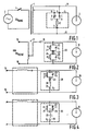
- Fig. 2 is a circuit diagram of a first embodiment of the starter-igniter apparatus in accordance with the invention.
- the customary AC supply voltage of 277 volts at 50/60 Hz is applied to input terminals 15-16.
- a constant wattage autotransformer 17 supplies an AC voltage of the order of 270 RMS volts to a double-ended metal halide discharge lamp 18 via a series connected capacitor 19.
- the autotransformer and capacitor provide the customary ballast function for limiting lamp current when the lamp is in its normal operating condition.
- a two-terminal starter-igniter device 20 is connected in parallel with the discharge lamp.
- the igniter device includes a first parallel RC network composed of a resistor 21 of resistance R1 and a capacitor 22 of capacitance C1.
- a second network consisting of a bilateral semiconductor switch 23, for example, a Sidac, in series with a second parallel RC network including a resistor 24 of resistance R2 and a capacitor 25 of capacitance C2, is connected in series circuit with the first RC network between the two terminals of the starter circuit 20.
- the series circuit 21-25 is thus in parallel with the discharge lamp 18.
- the usual peaky type open circuit voltage waveform provided by the constant wattage auto transformer ballast is further distorted by a high frequency voltage generated by the two-lead igniter 20. Ringing voltages are generated by the parallel RC combination of resistor 21 and capacitor 22 and by the further parallel RC network consisting of resistor 24 and capacitor 25. Switching of the ringing voltage is accomplished by the bilateral semiconductor switch 23.
- the total voltage generated across the terminals of the igniter 20 is the vector sum of the oscillatory voltages developed across the first parallel RC network (21, 22) , the second parallel RC network (24, 25) and the breakover voltage of the Sidac 23.
- the Sidac 23 may have a breakover voltage in the range of 235-260 volts where the igniter is used in combination with a constant wattage autotransformer for operating 175 W and 250 W metal halide double-ended discharge lamps.
- the values of the starter circuit components will differ for various types of ballasts and lamps. Nevertheless, the mode of operation of the circuit, as described above, remains essentially the same.
- the igniter 20 of Fig. 2 develops a peaky ringing voltage across the two capacitors which is switched on and off by the Sidac.
- the series-parallel combination of only five components, none of which is an inductor or pulse transformer, is connected across the lamp and secondary circuit of the ballast to generate a high pulse oscillating voltage which improves and makes more reliable the ignition of a metal halide lamp.
- the oscillating high frequency pulsatory voltages generated by the two parallel RC networks as the Sidac is switched on and off distorts the output voltage of the secondary circuit of the conventional ballast in a manner that produces an output voltage waveform for igniting the lamp that is very different from, and more effective than, that produced by prior art starter circuits.
- Fig. 3 illustrates a second embodiment of the starter-igniter apparatus in accordance with the invention. Similar circuit elements will be designated by the same reference numerals as in Fig. 2. This circuit is similar to Fig. 2 except that the igniter now is used in combination with an autotransformer lag ballast (not shown in detail for the sake of simplicity). Input terminals 15-16 are again connected to an AC supply voltage of, for example, 240 volts at 50-60 Hz. The igniter 20 omits the resistor 24 of Fig. 2 but now includes an inductor 26 connected in series with the capacitor 25. The Sidac 23, the inductor 26 and the capacitor 25 are connected in a series circuit.
- This series circuit is connected in series with the parallel RC network 21, 22 between the two terminals of the igniter 20, hence in parallel with the metal halide lamp 18.
- the components values are different than those in the igniter of Fig. 2.
- the capacitance C1 of capacitor 22 is increased in order to increase the distorted peaky open circuit voltage of the ballast thereby enabling the starter circuit to produce a better restrike capability.
- FIG. 4 A third embodiment of the invention is shown in Fig. 4 where, once again, similar circuit elements are designated by the same reference numerals as in the circuits of Figs. 2 and 3.
- the resistor 21 now is connected in parallel with the series combination of capacitor 22 and Sidac 23.
- the parallel network 21-23 is serially connected with an inductor 26 and the capacitor 25 between the two terminals of the igniter 20, which are in turn connected to the lamp electrodes so that the igniter circuit is again in parallel with the discharge lamp.
- This embodiment generated a distorted high frequency peaky open circuit voltage waveform similar to that generated by the igniter circuit of Fig. 2.
Landscapes
- Circuit Arrangements For Discharge Lamps (AREA)
Applications Claiming Priority (2)
| Application Number | Priority Date | Filing Date | Title |
|---|---|---|---|
| US311559 | 1989-02-15 | ||
| US07/311,559 US4959593A (en) | 1989-02-15 | 1989-02-15 | Two-lead igniter for HID lamps |
Publications (1)
| Publication Number | Publication Date |
|---|---|
| EP0383385A1 true EP0383385A1 (de) | 1990-08-22 |
Family
ID=23207444
Family Applications (1)
| Application Number | Title | Priority Date | Filing Date |
|---|---|---|---|
| EP90200294A Ceased EP0383385A1 (de) | 1989-02-15 | 1990-02-09 | Zweipolige Zündschaltung für Lampen mit starker Entladung |
Country Status (4)
| Country | Link |
|---|---|
| US (1) | US4959593A (de) |
| EP (1) | EP0383385A1 (de) |
| JP (1) | JPH02242593A (de) |
| CA (1) | CA2009805A1 (de) |
Cited By (3)
| Publication number | Priority date | Publication date | Assignee | Title |
|---|---|---|---|---|
| EP0595414A3 (de) * | 1992-10-29 | 1995-02-22 | Koninkl Philips Electronics Nv | Vorschaltgerät für eine Hochleistungsentladungslampe. |
| WO1999030538A1 (en) * | 1997-12-09 | 1999-06-17 | Koninklijke Philips Electronics N.V. | Ballast |
| US7982405B2 (en) | 2005-03-22 | 2011-07-19 | Lightech Electronic Industries Ltd. | Igniter circuit for an HID lamp |
Families Citing this family (13)
| Publication number | Priority date | Publication date | Assignee | Title |
|---|---|---|---|---|
| DE69103942T2 (de) * | 1990-04-02 | 1995-04-27 | Iwasaki Electric Co Ltd | Hochdruck-Metalldampfentladungslampe. |
| US6323603B1 (en) * | 1998-02-18 | 2001-11-27 | Nicollet Technologies Corporation | Resonant flyback ignitor circuit for a gas discharge lamp control circuit |
| US6157142A (en) * | 1998-10-15 | 2000-12-05 | Electro-Mag International, Inc. | Hid ballast circuit with arc stabilization |
| US6100652A (en) * | 1998-11-12 | 2000-08-08 | Osram Sylvania Inc. | Ballast with starting circuit for high-intensity discharge lamps |
| US6194843B1 (en) | 1999-01-29 | 2001-02-27 | Electro-Mag International, Inc. | HID ballast with hot restart circuit |
| US6320328B1 (en) * | 1999-04-30 | 2001-11-20 | Hubbell Incorporated | Method and apparatus for retrofitting gas discharge lamp ballast for use with gas discharge lamp having different power rating |
| US6545429B1 (en) * | 2000-06-08 | 2003-04-08 | Hubbell Incorporated | Lighting assembly having regulating transformer distally located from ballast |
| US6608451B2 (en) * | 2001-10-26 | 2003-08-19 | General Electric Company | Ballast circuit with an ignitor for starting multiple HID lamps |
| CN101282020B (zh) * | 2007-04-06 | 2010-10-13 | 豪利士电线装配(中山)有限公司 | 一种端子压著的方法及其控制装置 |
| JP2010003414A (ja) * | 2008-06-18 | 2010-01-07 | Iwasaki Electric Co Ltd | メタルハライドランプ |
| HUP1000054A3 (en) * | 2010-01-26 | 2012-08-28 | Gradix Holdings Ltd | Ac voltage converter and switching equipment |
| DE102010029146A1 (de) * | 2010-05-20 | 2011-11-24 | Osram Gesellschaft mit beschränkter Haftung | Schaltungsanordnung zum Zünden von Hochdruckentladungslampen |
| US8274239B2 (en) | 2010-06-09 | 2012-09-25 | General Electric Company | Open circuit voltage clamp for electronic HID ballast |
Citations (3)
| Publication number | Priority date | Publication date | Assignee | Title |
|---|---|---|---|---|
| GB1183543A (en) * | 1967-10-26 | 1970-03-11 | Gen Electric & English Elect | Improvements in or relating to Circuit Arrangements for Starting Electric Discharge Lamps from Alternating Current Supplies |
| US3758818A (en) * | 1969-07-25 | 1973-09-11 | New Nippon Electric Co | Starting circuit for discharge lamps |
| US3866088A (en) * | 1971-11-29 | 1975-02-11 | New Nippon Electric Co | Discharge lamp starter device using a backswing voltage booster and characterized by the absence of a preheating function |
Family Cites Families (2)
| Publication number | Priority date | Publication date | Assignee | Title |
|---|---|---|---|---|
| DE3108547A1 (de) * | 1981-03-06 | 1982-10-07 | Patent-Treuhand-Gesellschaft für elektrische Glühlampen mbH, 8000 München | "zuendschaltung fuer eine hochdruckmetalldampfentladungslampe" |
| US4876486A (en) * | 1987-12-30 | 1989-10-24 | Advance Transformer Co. | Two-lead starter circuit for a gaseous discharge lamp |
-
1989
- 1989-02-15 US US07/311,559 patent/US4959593A/en not_active Expired - Lifetime
-
1990
- 1990-02-09 EP EP90200294A patent/EP0383385A1/de not_active Ceased
- 1990-02-12 CA CA002009805A patent/CA2009805A1/en not_active Abandoned
- 1990-02-13 JP JP2029726A patent/JPH02242593A/ja active Pending
Patent Citations (3)
| Publication number | Priority date | Publication date | Assignee | Title |
|---|---|---|---|---|
| GB1183543A (en) * | 1967-10-26 | 1970-03-11 | Gen Electric & English Elect | Improvements in or relating to Circuit Arrangements for Starting Electric Discharge Lamps from Alternating Current Supplies |
| US3758818A (en) * | 1969-07-25 | 1973-09-11 | New Nippon Electric Co | Starting circuit for discharge lamps |
| US3866088A (en) * | 1971-11-29 | 1975-02-11 | New Nippon Electric Co | Discharge lamp starter device using a backswing voltage booster and characterized by the absence of a preheating function |
Cited By (3)
| Publication number | Priority date | Publication date | Assignee | Title |
|---|---|---|---|---|
| EP0595414A3 (de) * | 1992-10-29 | 1995-02-22 | Koninkl Philips Electronics Nv | Vorschaltgerät für eine Hochleistungsentladungslampe. |
| WO1999030538A1 (en) * | 1997-12-09 | 1999-06-17 | Koninklijke Philips Electronics N.V. | Ballast |
| US7982405B2 (en) | 2005-03-22 | 2011-07-19 | Lightech Electronic Industries Ltd. | Igniter circuit for an HID lamp |
Also Published As
| Publication number | Publication date |
|---|---|
| CA2009805A1 (en) | 1990-08-15 |
| JPH02242593A (ja) | 1990-09-26 |
| US4959593A (en) | 1990-09-25 |
Similar Documents
| Publication | Publication Date | Title |
|---|---|---|
| EP0222441B1 (de) | Wechselrichter zum Entzünden und Versorgen einer Entladungslampe | |
| US4958107A (en) | Switching arrangement for HID lamps | |
| US4959593A (en) | Two-lead igniter for HID lamps | |
| EP0408121B1 (de) | Schaltungsanordnung | |
| US3235769A (en) | Starting circuit for discharge lamps | |
| US4695771A (en) | Ignition circuit for high pressure arc discharge lamps | |
| US4890041A (en) | High wattage HID lamp circuit | |
| US4342948A (en) | Electric discharge lamp control converter circuits | |
| US6028401A (en) | Ignition scheme for a high pressure discharge lamp | |
| JPS61193399A (ja) | 高輝度放電ランプの始動および動作装置 | |
| KR200212643Y1 (ko) | 전자 램프 동작용 회로 장치 | |
| CA2037667C (en) | Ignitor for high pressure arc discharge lamps | |
| US6373199B1 (en) | Reducing stress on ignitor circuitry for gaseous discharge lamps | |
| US4339695A (en) | High pressure sodium lamp ballast circuit | |
| US4853598A (en) | Fluorescent lamp controlling | |
| US4103209A (en) | Add-on instant restrike device for an hid lamp | |
| US4441056A (en) | High pressure sodium lamp ballast circuit | |
| US4950961A (en) | Starting circuit for gaseous discharge lamps | |
| US5572093A (en) | Regulation of hot restrike pulse intensity and repetition | |
| KR0169164B1 (ko) | 순간점등형 형광램프 점등회로 | |
| US4066932A (en) | Saturable reactor device for operating a discharge lamp | |
| JPH0744076B2 (ja) | 放電灯点灯装置 | |
| GB2117193A (en) | Electric discharge lamp operating circuit | |
| RU2211549C2 (ru) | Устройство для зажигания газоразрядной лампы | |
| KR830000940B1 (ko) | 방전등 점등장치 |
Legal Events
| Date | Code | Title | Description |
|---|---|---|---|
| PUAI | Public reference made under article 153(3) epc to a published international application that has entered the european phase |
Free format text: ORIGINAL CODE: 0009012 |
|
| AK | Designated contracting states |
Kind code of ref document: A1 Designated state(s): AT BE CH DE FR GB LI NL |
|
| 17P | Request for examination filed |
Effective date: 19910219 |
|
| 17Q | First examination report despatched |
Effective date: 19930301 |
|
| RAP1 | Party data changed (applicant data changed or rights of an application transferred) |
Owner name: PHILIPS ELECTRONICS NORTH AMERICA CORPORATION |
|
| STAA | Information on the status of an ep patent application or granted ep patent |
Free format text: STATUS: THE APPLICATION HAS BEEN REFUSED |
|
| 18R | Application refused |
Effective date: 19960429 |