EP0383444A2 - Porte-connecteur - Google Patents
Porte-connecteur Download PDFInfo
- Publication number
- EP0383444A2 EP0383444A2 EP90300795A EP90300795A EP0383444A2 EP 0383444 A2 EP0383444 A2 EP 0383444A2 EP 90300795 A EP90300795 A EP 90300795A EP 90300795 A EP90300795 A EP 90300795A EP 0383444 A2 EP0383444 A2 EP 0383444A2
- Authority
- EP
- European Patent Office
- Prior art keywords
- connectors
- holder
- wall
- center
- front wall
- Prior art date
- Legal status (The legal status is an assumption and is not a legal conclusion. Google has not performed a legal analysis and makes no representation as to the accuracy of the status listed.)
- Granted
Links
- 238000002955 isolation Methods 0.000 description 20
- 230000013011 mating Effects 0.000 description 9
- 238000010276 construction Methods 0.000 description 4
- 238000006073 displacement reaction Methods 0.000 description 4
- 238000003780 insertion Methods 0.000 description 4
- 230000037431 insertion Effects 0.000 description 4
- 238000009413 insulation Methods 0.000 description 3
- 238000000605 extraction Methods 0.000 description 2
- 238000004519 manufacturing process Methods 0.000 description 2
- 239000000463 material Substances 0.000 description 2
- 238000000034 method Methods 0.000 description 2
- 238000005516 engineering process Methods 0.000 description 1
- 229920002457 flexible plastic Polymers 0.000 description 1
- 239000012778 molding material Substances 0.000 description 1
- 229920003023 plastic Polymers 0.000 description 1
- 230000000717 retained effect Effects 0.000 description 1
Images

Classifications
-
- H—ELECTRICITY
- H01—ELECTRIC ELEMENTS
- H01R—ELECTRICALLY-CONDUCTIVE CONNECTIONS; STRUCTURAL ASSOCIATIONS OF A PLURALITY OF MUTUALLY-INSULATED ELECTRICAL CONNECTING ELEMENTS; COUPLING DEVICES; CURRENT COLLECTORS
- H01R9/00—Structural associations of a plurality of mutually-insulated electrical connecting elements, e.g. terminal strips or terminal blocks; Terminals or binding posts mounted upon a base or in a case; Bases therefor
-
- H—ELECTRICITY
- H01—ELECTRIC ELEMENTS
- H01R—ELECTRICALLY-CONDUCTIVE CONNECTIONS; STRUCTURAL ASSOCIATIONS OF A PLURALITY OF MUTUALLY-INSULATED ELECTRICAL CONNECTING ELEMENTS; COUPLING DEVICES; CURRENT COLLECTORS
- H01R13/00—Details of coupling devices of the kinds covered by groups H01R12/70 or H01R24/00 - H01R33/00
- H01R13/46—Bases; Cases
- H01R13/516—Means for holding or embracing insulating body, e.g. casing, hoods
- H01R13/518—Means for holding or embracing insulating body, e.g. casing, hoods for holding or embracing several coupling parts, e.g. frames
Definitions
- This invention relates to an electrical connector, more specifically to an electrical connector holder to hold a pair of electrical connectors in parallel with each other.
- a box-type holder is formed by opening only at the one side plane along the rear surface from which electrical wires extend.
- Connectors having receptacle-type contacts are mated in parallel from the open side plane of the holder. Under this mated condition, the connectors are electrically connected by mating with a matable connector having male contacts.
- the above holder is bulky due to both sidewalls along its length. Therefore, such holder is not suitable to meet the overall compact connector design.
- a connector having a relatively large number of contacts requires a relatively larger holder to mate with such connector.
- Another problem associated with a larger holder is increased warping of the sidewalls along its length, which results in poor operability of the connector with respect to the holder.
- the connector holder in accordance with the present invention has a pair of connector-holding chambers.
- the chambers are constructed by an elongated front wall, a narrow center isolation wall crossing the front wall at the center portion along the length of the front wall, and end walls crossing at both ends of the center isolation wall in its width direction.
- the chambers are separated by the center isolation wall and open opposite to the front wall and the center isolation wall.
- a plurality of apertures are formed along the length of the front wall at a constant pitch through which contacts of mating connectors extend.
- First and second latch means respectively are located on the end walls and the center isolation wall for engagement with the connectors to latch them in the chambers.
- the first latch means engage ear sections on the end walls at substantially a center position along the width of the connectors to be latched in the holding chambers.
- the second engaging means are located on the isolation wall for engaging a rear surface of the connectors.
- the first latch means are made of projections extending inwardly from the free ends (remote from the bases) of the end walls and extending across the center isolation wall.
- the second latch means are made of at least one projection on the center isolation wall at the remote edge from the front wall in an intermediate region along the length of the center isolation wall.
- the projection has a sloped outer surface and an inner surface essentially at a right angle to the plane of the center isolation wall.
- connectors are latchably maintained in the connector-holding chambers divided into two sections by the center isolation wall.
- the latchably maintained condition is further enhanced by the first latch means on the end walls and the second latch means on the center isolation wall.
- the two connectors thus retained by the holder are mated with a mating connector.
- contacts of the latter connector are electrically connected to contacts of the former connectors by way of apertures disposed in the front wall of the holder at a constant pitch.
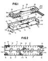
- the holder 10 is preferably made of a flexible plastic material and comprises an elongated front wall 11 facing a mating connector (not shown), an elongated center isolation wall 12 crossing integrally at the center of the front wall 11 along the length thereof, and end walls 13a, 13b, 14a, 14b crossing at both ends of the front wall 11 and the center isolation wall 12.
- the height of the end walls is chosen to be slightly shorter than the height of front portions 11a, 11b on each side of the center isolation wall 12.
- Formed at the upper ends of the end walls 13a, 13b and the lower ends of the end walls 14a, 14 are a first latch means 15 extending inwardly therefrom.
- a second latch means 16 in the form of triangles with sloped outer surfaces at the rear end portion of the center isolation wall 12 opposite to the front wall 11 at a constant pitch along the length thereof.
- Apertures 17 are formed near upper and lower edge portions of the front wall 11 in correspondence with the arrangement of female contacts (not shown) secured in the connector 20 at a constant pitch. Male contacts of a mating connector extend through the apertures 17 for making electrical connection with the female contacts.
- the connectors 20 include a housing 21 which are made of an insulative material such as plastic and has cavities 22 at the pitch of the female contacts.
- the cavities 22 are open at a rear surface and a bottom surface of the housing 21.
- the female-type contacts in which electrical wires 27 are insulation displacement connected are mounted into the cavities 22 from the open bottom surface and engaged by flexible engaging members 23 to prevent backward movement.
- the width of the housing 21 transverse to the longitudinal direction thereof is chosen to be substantially equal to the distance between the inner surface of the front wall 11 of the holder 10 and the inner surface of the second latch means 16.
- the height of the housing 21 is chosen to be substantially equal to the height of the front wall 11a, 11b.
- the connectors 20 may be mated with the holder 10 from the rear direction. However, this operation is relatively difficult as compared with mating in a vertical direction from the upper or lower direction. It is therefore normal to mate or remove in a vertical direction.
- the projections 26 are provided to prevent the connectors 20 from being mated with the holder 10 in an up-side-down direction.
- the second latch means 16 is most preferably formed on the center isolation wall 12 as in the shown embodiment. This is sufficient to prevent the connectors 20 from unintentionally slipping out backwardly. However, if the holder 10 and the connectors 20 are relatively short, such second latch means may be formed at appropriate locations of the end walls 13a, 13b, 14a, 14b.
- a center isolation wall is formed along the center of a front wall of a holder in crossing relationship therewith, the side walls of the holder facing and latchably engaging connectors positioned therein. It is, therefore, a low profile design as compared with a conventional box-type holder and economical with minimum molding material for the holder.
- latch means are provided to firmly secure the mated connectors therein by preventing unintentional movement or slipping out of the connectors in any direction.
- Such holder construction overcomes any disadvantages associated with the conventional elongated connector design having a large number of contacts, i.e., increased insertion and removal forces of the connectors into and out of the holder. Rather, such particular construction of the holder enhances flexibility to ease insertion and removal operations of the connectors.
- the center isolation wall may be relatively thin; because with the connectors mated with the holder, the center wall is strengthened.
Landscapes
- Connector Housings Or Holding Contact Members (AREA)
- Details Of Connecting Devices For Male And Female Coupling (AREA)
- Coupling Device And Connection With Printed Circuit (AREA)
Applications Claiming Priority (2)
| Application Number | Priority Date | Filing Date | Title |
|---|---|---|---|
| JP1989014977U JPH0729582Y2 (ja) | 1989-02-11 | 1989-02-11 | コネクタ保持体 |
| JP14977/89 | 1989-02-11 |
Publications (3)
| Publication Number | Publication Date |
|---|---|
| EP0383444A2 true EP0383444A2 (fr) | 1990-08-22 |
| EP0383444A3 EP0383444A3 (fr) | 1991-11-06 |
| EP0383444B1 EP0383444B1 (fr) | 1995-03-22 |
Family
ID=11876040
Family Applications (1)
| Application Number | Title | Priority Date | Filing Date |
|---|---|---|---|
| EP90300795A Expired - Lifetime EP0383444B1 (fr) | 1989-02-11 | 1990-01-25 | Porte-connecteur |
Country Status (6)
| Country | Link |
|---|---|
| US (1) | US4964817A (fr) |
| EP (1) | EP0383444B1 (fr) |
| JP (1) | JPH0729582Y2 (fr) |
| KR (1) | KR950009903B1 (fr) |
| DE (1) | DE69017929T2 (fr) |
| PT (1) | PT93083B (fr) |
Cited By (1)
| Publication number | Priority date | Publication date | Assignee | Title |
|---|---|---|---|---|
| GB2260658A (en) * | 1991-10-17 | 1993-04-21 | Whitaker Corp | Electrical connector with module holder |
Families Citing this family (6)
| Publication number | Priority date | Publication date | Assignee | Title |
|---|---|---|---|---|
| JP3262732B2 (ja) * | 1997-02-24 | 2002-03-04 | 日本圧着端子製造株式会社 | コネクタホルダー |
| US6547605B2 (en) * | 2001-07-20 | 2003-04-15 | Delphi Technologies, Inc. | Flex circuit electrical connector |
| JP7035770B2 (ja) | 2018-04-27 | 2022-03-15 | 京セラドキュメントソリューションズ株式会社 | コネクターホルダー |
| JP6897632B2 (ja) | 2018-05-24 | 2021-07-07 | 京セラドキュメントソリューションズ株式会社 | コネクターホルダー |
| KR102147266B1 (ko) * | 2020-04-28 | 2020-08-24 | (주) 여명기술단 | 외부 통신망과 연결된 옥내 인터넷 통신공유기 |
| KR102147270B1 (ko) * | 2020-04-28 | 2020-08-24 | (주) 여명기술단 | 실내 통신케이블 접속기구 |
Family Cites Families (10)
| Publication number | Priority date | Publication date | Assignee | Title |
|---|---|---|---|---|
| US2469397A (en) * | 1945-11-14 | 1949-05-10 | Melvin E Mezek | Electrical connector |
| US3140139A (en) * | 1961-11-02 | 1964-07-07 | Grayhill Moldtronics Inc | Connector assembly |
| US3148929A (en) * | 1962-08-09 | 1964-09-15 | Elco Corp | Sheet metal contact with slug |
| US4243289A (en) * | 1979-07-18 | 1981-01-06 | Methode Electronics, Inc. | Electrical male connector assembly |
| DE3012174C2 (de) * | 1980-03-28 | 1984-11-29 | Siemens AG, 1000 Berlin und 8000 München | Mehrfachsteckverbinder |
| US4327958A (en) * | 1980-05-05 | 1982-05-04 | Amp Incorporated | Connector jack |
| JPS5942785A (ja) * | 1982-08-31 | 1984-03-09 | 日本圧着端子製造株式会社 | 電気コネクタ |
| US4596436A (en) * | 1985-03-25 | 1986-06-24 | Amp Incorporated | Electrical connector housing assembly comprising housing frame containing housing modules |
| US4881904A (en) * | 1988-09-20 | 1989-11-21 | Augat Inc. | Modular electrical connector |
| JPH02223171A (ja) * | 1988-11-24 | 1990-09-05 | Yazaki Corp | 多段式コネクタ並びに電線圧接方法 |
-
1989
- 1989-02-11 JP JP1989014977U patent/JPH0729582Y2/ja not_active Expired - Lifetime
- 1989-12-13 US US07/450,353 patent/US4964817A/en not_active Expired - Lifetime
-
1990
- 1990-01-25 EP EP90300795A patent/EP0383444B1/fr not_active Expired - Lifetime
- 1990-01-25 DE DE69017929T patent/DE69017929T2/de not_active Expired - Fee Related
- 1990-02-08 PT PT93083A patent/PT93083B/pt not_active IP Right Cessation
- 1990-02-09 KR KR1019900001567A patent/KR950009903B1/ko not_active Expired - Fee Related
Cited By (3)
| Publication number | Priority date | Publication date | Assignee | Title |
|---|---|---|---|---|
| GB2260658A (en) * | 1991-10-17 | 1993-04-21 | Whitaker Corp | Electrical connector with module holder |
| FR2683682A1 (fr) * | 1991-10-17 | 1993-05-14 | Amp Inc | Assemblage de connecteur electrique. |
| GB2260658B (en) * | 1991-10-17 | 1995-08-02 | Whitaker Corp | Electrical connector with module holder |
Also Published As
| Publication number | Publication date |
|---|---|
| EP0383444A3 (fr) | 1991-11-06 |
| EP0383444B1 (fr) | 1995-03-22 |
| PT93083A (pt) | 1991-10-31 |
| DE69017929D1 (de) | 1995-04-27 |
| US4964817A (en) | 1990-10-23 |
| JPH02106688U (fr) | 1990-08-24 |
| JPH0729582Y2 (ja) | 1995-07-05 |
| PT93083B (pt) | 1998-01-30 |
| KR900013671A (ko) | 1990-09-06 |
| KR950009903B1 (ko) | 1995-09-01 |
| DE69017929T2 (de) | 1995-11-02 |
Similar Documents
| Publication | Publication Date | Title |
|---|---|---|
| US4934947A (en) | Modular jack for flat flexible cable | |
| US5876217A (en) | Electric connector assembly with improved retention characteristics | |
| EP0388216B1 (fr) | Connecteur électrique pour câble plat | |
| US4695112A (en) | Printed circuit board, edgeboard connector therefor | |
| US4867711A (en) | Connector with double lock | |
| US4428636A (en) | Multi-contact connectors for closely spaced conductors | |
| US6183287B1 (en) | Electrical connector | |
| US5004436A (en) | Electrical connector | |
| EP0080772B1 (fr) | Assemblage électrique d'une fiche et d'une douille | |
| KR100231122B1 (ko) | 개선된 배치 수단을 갖는 전기 커넥터 | |
| EP0201236A1 (fr) | Assemblage de plaque à circuit électrique | |
| US6183315B1 (en) | Board-to-board connector assembly | |
| US5281161A (en) | Electrical connector with module holder | |
| US4971580A (en) | High density electrical connector with terminal retention latch | |
| US4693532A (en) | Modular staggered multi-row electrical connector | |
| JPH0797507B2 (ja) | モジュラープラグ用ジヤツク | |
| US5061198A (en) | Electrical connector system | |
| US6093061A (en) | Electrical connector having terminal insert subassembly | |
| WO1985005501A1 (fr) | Boitier de connecteur electrique | |
| US4710135A (en) | Electrical connector having integral latch means | |
| EP0862805B1 (fr) | Connecteur electrique a peigne pour le positionnement de fils | |
| EP0740372B1 (fr) | Connecteur électrique | |
| US3992072A (en) | Electrical connector | |
| GB2232827A (en) | Electrical connector system for coaxial cable | |
| US5588877A (en) | Electrical connector with multiple blade contacts |
Legal Events
| Date | Code | Title | Description |
|---|---|---|---|
| PUAI | Public reference made under article 153(3) epc to a published international application that has entered the european phase |
Free format text: ORIGINAL CODE: 0009012 |
|
| AK | Designated contracting states |
Kind code of ref document: A2 Designated state(s): DE FR GB |
|
| 17P | Request for examination filed |
Effective date: 19901227 |
|
| PUAL | Search report despatched |
Free format text: ORIGINAL CODE: 0009013 |
|
| AK | Designated contracting states |
Kind code of ref document: A3 Designated state(s): DE FR GB |
|
| RAP1 | Party data changed (applicant data changed or rights of an application transferred) |
Owner name: THE WHITAKER CORPORATION |
|
| 17Q | First examination report despatched |
Effective date: 19940331 |
|
| GRAA | (expected) grant |
Free format text: ORIGINAL CODE: 0009210 |
|
| AK | Designated contracting states |
Kind code of ref document: B1 Designated state(s): DE FR GB |
|
| REF | Corresponds to: |
Ref document number: 69017929 Country of ref document: DE Date of ref document: 19950427 |
|
| ET | Fr: translation filed | ||
| PLBE | No opposition filed within time limit |
Free format text: ORIGINAL CODE: 0009261 |
|
| STAA | Information on the status of an ep patent application or granted ep patent |
Free format text: STATUS: NO OPPOSITION FILED WITHIN TIME LIMIT |
|
| 26N | No opposition filed | ||
| PGFP | Annual fee paid to national office [announced via postgrant information from national office to epo] |
Ref country code: GB Payment date: 20011214 Year of fee payment: 13 |
|
| REG | Reference to a national code |
Ref country code: GB Ref legal event code: IF02 |
|
| PGFP | Annual fee paid to national office [announced via postgrant information from national office to epo] |
Ref country code: FR Payment date: 20020104 Year of fee payment: 13 |
|
| PGFP | Annual fee paid to national office [announced via postgrant information from national office to epo] |
Ref country code: DE Payment date: 20020131 Year of fee payment: 13 |
|
| PG25 | Lapsed in a contracting state [announced via postgrant information from national office to epo] |
Ref country code: GB Free format text: LAPSE BECAUSE OF NON-PAYMENT OF DUE FEES Effective date: 20030125 |
|
| PG25 | Lapsed in a contracting state [announced via postgrant information from national office to epo] |
Ref country code: DE Free format text: LAPSE BECAUSE OF NON-PAYMENT OF DUE FEES Effective date: 20030801 |
|
| GBPC | Gb: european patent ceased through non-payment of renewal fee | ||
| PG25 | Lapsed in a contracting state [announced via postgrant information from national office to epo] |
Ref country code: FR Free format text: LAPSE BECAUSE OF NON-PAYMENT OF DUE FEES Effective date: 20030930 |
|
| REG | Reference to a national code |
Ref country code: FR Ref legal event code: ST |