EP0383459A2 - Automatischer Injektor für Kapillare - Google Patents
Automatischer Injektor für Kapillare Download PDFInfo
- Publication number
- EP0383459A2 EP0383459A2 EP90301064A EP90301064A EP0383459A2 EP 0383459 A2 EP0383459 A2 EP 0383459A2 EP 90301064 A EP90301064 A EP 90301064A EP 90301064 A EP90301064 A EP 90301064A EP 0383459 A2 EP0383459 A2 EP 0383459A2
- Authority
- EP
- European Patent Office
- Prior art keywords
- capillary
- vial
- sample
- cartridge
- pressure
- Prior art date
- Legal status (The legal status is an assumption and is not a legal conclusion. Google has not performed a legal analysis and makes no representation as to the accuracy of the status listed.)
- Withdrawn
Links
- 238000005070 sampling Methods 0.000 claims description 20
- 239000012528 membrane Substances 0.000 claims description 9
- 239000012858 resilient material Substances 0.000 claims 2
- 230000008878 coupling Effects 0.000 claims 1
- 238000010168 coupling process Methods 0.000 claims 1
- 238000005859 coupling reaction Methods 0.000 claims 1
- 210000001736 capillary Anatomy 0.000 abstract description 111
- 229940090045 cartridge Drugs 0.000 abstract description 60
- 238000002347 injection Methods 0.000 abstract description 27
- 239000007924 injection Substances 0.000 abstract description 27
- 238000000034 method Methods 0.000 abstract description 20
- 238000007789 sealing Methods 0.000 abstract description 18
- 230000010354 integration Effects 0.000 abstract description 14
- 238000001962 electrophoresis Methods 0.000 abstract description 10
- 239000003792 electrolyte Substances 0.000 abstract description 9
- 239000012530 fluid Substances 0.000 abstract description 9
- 230000008569 process Effects 0.000 abstract description 7
- 239000007788 liquid Substances 0.000 abstract description 5
- 238000003780 insertion Methods 0.000 abstract description 4
- 230000037431 insertion Effects 0.000 abstract description 4
- 230000001419 dependent effect Effects 0.000 abstract description 2
- 238000012544 monitoring process Methods 0.000 abstract description 2
- 229940090044 injection Drugs 0.000 description 23
- 230000008901 benefit Effects 0.000 description 9
- 239000000463 material Substances 0.000 description 9
- 229920001971 elastomer Polymers 0.000 description 6
- 210000003811 finger Anatomy 0.000 description 6
- 238000010276 construction Methods 0.000 description 5
- 239000007789 gas Substances 0.000 description 5
- 238000005251 capillar electrophoresis Methods 0.000 description 4
- 230000000694 effects Effects 0.000 description 4
- 238000005259 measurement Methods 0.000 description 4
- 208000036366 Sensation of pressure Diseases 0.000 description 3
- 230000008859 change Effects 0.000 description 3
- 239000002826 coolant Substances 0.000 description 3
- 230000000875 corresponding effect Effects 0.000 description 3
- 238000004128 high performance liquid chromatography Methods 0.000 description 3
- IJGRMHOSHXDMSA-UHFFFAOYSA-N Atomic nitrogen Chemical compound N#N IJGRMHOSHXDMSA-UHFFFAOYSA-N 0.000 description 2
- 230000006870 function Effects 0.000 description 2
- 238000002360 preparation method Methods 0.000 description 2
- 239000000565 sealant Substances 0.000 description 2
- 239000000126 substance Substances 0.000 description 2
- 238000012952 Resampling Methods 0.000 description 1
- 238000004458 analytical method Methods 0.000 description 1
- 238000004587 chromatography analysis Methods 0.000 description 1
- 229940000425 combination drug Drugs 0.000 description 1
- 238000004891 communication Methods 0.000 description 1
- 150000001875 compounds Chemical class 0.000 description 1
- 238000004590 computer program Methods 0.000 description 1
- 239000012809 cooling fluid Substances 0.000 description 1
- 238000001514 detection method Methods 0.000 description 1
- 238000010586 diagram Methods 0.000 description 1
- 238000006073 displacement reaction Methods 0.000 description 1
- 238000011067 equilibration Methods 0.000 description 1
- 238000007373 indentation Methods 0.000 description 1
- 238000001746 injection moulding Methods 0.000 description 1
- 230000000266 injurious effect Effects 0.000 description 1
- 238000012423 maintenance Methods 0.000 description 1
- 230000007246 mechanism Effects 0.000 description 1
- 238000000465 moulding Methods 0.000 description 1
- 229910052757 nitrogen Inorganic materials 0.000 description 1
- 239000002245 particle Substances 0.000 description 1
- 230000000149 penetrating effect Effects 0.000 description 1
- 230000035515 penetration Effects 0.000 description 1
- 239000004033 plastic Substances 0.000 description 1
- 238000003825 pressing Methods 0.000 description 1
- 230000002035 prolonged effect Effects 0.000 description 1
- 229920002379 silicone rubber Polymers 0.000 description 1
- 238000012546 transfer Methods 0.000 description 1
- 238000005406 washing Methods 0.000 description 1
Images



Classifications
-
- G—PHYSICS
- G01—MEASURING; TESTING
- G01N—INVESTIGATING OR ANALYSING MATERIALS BY DETERMINING THEIR CHEMICAL OR PHYSICAL PROPERTIES
- G01N27/00—Investigating or analysing materials by the use of electric, electrochemical, or magnetic means
- G01N27/26—Investigating or analysing materials by the use of electric, electrochemical, or magnetic means by investigating electrochemical variables; by using electrolysis or electrophoresis
- G01N27/416—Systems
- G01N27/447—Systems using electrophoresis
- G01N27/44704—Details; Accessories
- G01N27/44743—Introducing samples
Definitions
- This invention relates to electrophoresis. More particularly in capillary electrophoresis an injection technique is disclosed for injecting sample to a capillary, the capillary preferably being held within a cartridge.
- Capillary electrophoresis is known. Typically a capillary (in the order of 50 microns inside diameter) is filled with electrolyte. The width of the capillary is 350 microns outside diameter. The length of the capillary is from 20 to 100 cm. Consequently it has a total volume in the order of 1 to 2 microliters. Need strictlyless to say, the capillary is fragile.
- the capillary is initially filled with electrolyte. Sample must be accurately injected in small amounts for the required analysis by electrophoresis.
- a pressure integrated apparatus and process for the measured injection of sample into a capillary for electrophoresis is disclosed.
- the capillary is mounted in a serpentine path to a cartridge body having a bottom.
- the capillary, previously filled with electrolyte depends a distance below the bottom of the cartridge and has its periphery sealed to the cartridge.
- the cartridge is registered at the depending capillary to a vial of sample. The vial of sample is moved into substantial gas tight relation with the cartridge so that the depending capillary is below the surface of liquid within the sample vial.
- the vial is then communicated to a source of substantially constant fluid pressure in the order of 1 lb./inch2.
- a pressure gauge monitors the pressure of the vial and outputs a signal to integration apparatus such as a microprocessor.
- integration apparatus such as a microprocessor.
- An object to this invention is to disclose a simple and volumetrically accurate method for the injection of sample to an electrolyte filled capillary in preparation for electrophoresis.
- the capillary depends downward from the bottom of a cartridge body.
- the capillary is sealed at its perimeter to the cartridge body.
- the capillary, already flooded with electrolyte, is immersed in a sample containing vial.
- the vial is confronted and sealed substantially air tight to the bottom of the cartridge around the capillary.
- Pressure is supplied to the capillary from a substantially constant pressure source -- in the range of 1 psi. Fluid is injected to the capillary.
- An advantage of this method and apparatus for pressure injection is that the capillary when held by the cartridge is uniquely positioned for sample injection.
- a further object of the invention is to disclose apparatus for the precision measurement of injected sample.
- the pressure within the sample vial is closely monitored by a pressure transducer.
- the pressure transducer outputs to an integration device, such as a microprocessor.
- An advantage of this aspect to the apparatus and process is that high accuracy of the injection technique can be achieved. At the same time, very small amounts of sample can be injected. In sample injections of the magnitude of five nanoliters, into a cartridge containing several microliters, reproducible results of the sample injection in the range of plus or minus 2% have been achieved!
- a further advantage of the injection technique is that the reliance on a perfect seal between the vial and the capillary is not required. Where slow -- but relatively constant -- leaks change the pressure in the sample vial from which sample injection occurs, the integration is capable of preserving accurate measurement. Simply stated, by knowing accurately the pressure of the vial, adjustments to the integration can be made to vary the time exposure of the capillary to the extant sample.
- An advantage of this aspect of the invention is that the integration can be adjusted for nonlinearilyties encountered. For example, when the sample is initially pressurized, flow into the capillary will not be linear with pressure. Likewise, when the sample is depressurized at the end of sample injection, nonlinearities and flow rate will likewise be encountered. Specifically, these nonlinearities can be tailored in the integration. Further, the nonlinearities can be adjusted to the particular pressure which happens to be present when the sample is injected.
- An additional advantage of this aspect of the invention is that adjustment can easily be made for the viscosity of the sample.
- Yet another object to this invention is to disclose an automated sequence for sample injection to a cartridge mounted capillary.
- a lever arm having paired hypodermics is registered underlying the depending capillary and overlying the septum of the vial.
- the vial is first moved upwardly, piercing of the septum at the hypodermics first occurs. Thereafter, the lever arm is forced between the vial and the overlying cartridge to register to a block having paired O-ring seals between the cartridge at the upper end and the lever arm around the hypodermics at the lower end.
- the capillary passes through one of the hypodermics into the sample containing the vial.
- An advantage of this aspect of the invention is for the first time sample injection in a capillary electrophoresis application can be completely automated to a high degree of accuracy.
- a vial cap having downwardly movable resilient flaps is provided.
- the flaps are surrounded by an O-ring sealing structure.
- the lever arm has downwardly depending fingers, rather than hypodermics. The fingers move the flaps downward to form an opening for insertion of the capillary and/or electrode.
- the O-ring forms a seal with the lever arm to permit vial pressurization.
- This embodiment also provides for automated sampling, and further permits reuse or resampling of the vial.
- Cartridge C defines an interior volume V, which volume V contains coolant during cartridge confined electrophoresis.
- Capillary Q is initially threaded through aperture 12 and passed a sufficient number of times around a mandrel M having helical threads 11. Threads 11 are given sufficient depth and spacing so that remote parts of the capillary do not make electric contact or arc through the capillary during the electrophoretic process. As illustrated in the exploded perspective of Fig. 1A, the mandrel is first wound and thereafter inserted interior of the volume V in the cartridge C.
- the capillary Q typically is aligned along vertical surface 14 to the first wind around mandrel M. After the requisite number of turns to accommodate the intended length of the capillary, the capillary passes over exit surface 15. At this surface the capillary gradually turns vertically downward departing exit surface 15 at point 16. Thereafter, the capillary passes across the detector aperture D, along a vertical exit passage 19 and finally through an exit aperture 17.
- the capillary Q is registered to a bar 18 within detector D, this bar having a small central aperture for the passage of light. As will hereinafter be set forth, passage of the light through the cartridge C at detector D allows the classified components to be identified.
- a cover 24 is placed over and sealed in position, enclosing the cartridge.
- Fig. IB the rear surface of the cartridge can be seen and understood.
- Detector D has a concentric and essentially circular gathering surface 25 for aligning optics to the aperture 26.
- plate 24 has a similar aperture 27.
- the rear of the cartridge is essentially rectilinear.
- conduits 21 and 22 are for the entry and exit of cooling fluid used during the electrophoresis within the cartridge C. It can be seen that the conduits start at the bottom surface of cartridge C and extend into the volume V. Thus, before the electric potential is placed across the distal ends of the capillary Q, the entire volume of the cartridge C can be flooded with coolant. Likewise, and immediately before cartridges are removed, draining of the inner volume V can likewise occur.
- capillary Q Immediately before block 24 closes cartridge C, capillary Q has sealant placed on apertures 12 and 17.
- sealant preferably a silicon rubber compound, effects a sealing of the periphery of the capillary Q to the cartridge C. As will hereafter become more apparent, this sealing enables fluid to be forced under pressure up the interior of the capillary Q.
- an outer concentric table T1 and an inner concentric table T2 contain a series of vials.
- Vials Vl-V24 are contained at 24 spaced apart angular intervals about circular outer concentric table T1.
- Vials V25 through V35 are contained in the inner concentric table T2.
- vials Vl and V25 are respectively registered under a cartridge C.
- Capillary Q interior of cartridge not only occupies the serpentine path previously described but depends at respective distal ends 28 and 30 from the bottom of the cartridge. It is these distal ends 28 and 30 which penetrate into and receive sample from the vials.
- end 28 depends into vial V1 and receives sample from that vial. At that same time, and in order to equilibrate pressure flow across the capillary, end 3u penetrates into vial 25. Unlike vial V1, vial 25 fluidly communicates with atmosphere. Thus any flow rate into the capillary Q will be dependent upon pressure placed on the sample in vial V1.
- Vial V1 is illustrated, urged upwardly by piston P1.
- Vial V1 contains a sample 30. It is the purpose of this invention to inject sample 30 into the capillary Q which capillary has already been filled by electrolyte.
- a block B is intermediate the cartridge C and the vial V.
- the purpose of block B1 can be discussed first. Its construction will thereafter easily follow.
- block B1 The purpose of block B1 is to permit a pressure seal of the vial V with respect to the cartridge C.
- capillary Q is sealed at seal 34 at the point where it depends from the cartridge C. Such sealing occurs around the periphery of the capillary C.
- capillary C is very small.
- capillary C can be in the order of 50 microns inside diameter.
- the outside diameter of the capillary C will be on the order of 500 microns.
- a volume in the order of 1 to 2 microliters will constitute the entire volume of the capillary.
- the capillary is filled with electrolyte.
- block B includes a first overlying set of O rings 40 and a second underlying set of O rings 42.
- seals can be other than perfect.
- the seal around the periphery 34 of the capillary Q at the cartridge can leak.
- leakage can also occur at O rings 40, 44.
- block B1 The construction of block B1 may now be set forth.
- aperture 50 it has a first aperture 50. It is through aperture 50 that gas (preferably nitrogen) is introduced under constant pressure. Such introduction occurs only after the seals 40, 42 are registered respectively to the cartridge C and vial V1.
- gas preferably nitrogen
- Aperture 52 is for the accurate measure of pressure interior of the vial V1. Specifically, by knowing precisely the pressure interior of the vial V1, accurate integration with respect to time of the pressure within the vial V can occur.
- a pressure transducer 60 reads the pressure interior of conduit 52 on block B1. Pressure transducer 60 outputs a signal to integrator I.
- Integrator I has an operative connection to a solenoid valve S through a solenoid 70.
- a solenoid valve S By the sequence of opening solenoid valve 70, integrating the pressure interior of the vial V1 with respect to time and closing the solenoid valve S responsive to a measured amount of sample, quantitative measure of sample injected to the capillary tube can be made.
- a pressure time integration is disclosed. Assuming that solenoid valve S opens at t0, pressure equilibration will take place in a time interval t0-t1. When full pressure is reached (here shown in the range of 1 psig), that pressure remains on the capillary until until time t2. At time t2, solenoid valve S will close.
- nonlinearities are present. These nonlinearities are between time to and time t1 and after time t2. For the convenience of the viewer, the nonlinearities are shaded.
- nonlinearities will change. Specifically, the nonlinearity between the time t0 and time t′1 when vial V realizes a constant pressure will have changed. Likewise, the nonlinearity present after t′2 will likewise have changed.
- sample viscosity can be such a factor.
- Temperature of the sample can likewise effect flow rate. Appropriate adjustment can be made by those skilled in the art.
- Pressure transducer 60 is a transducer manufactured by the Fujikura company of Japan.
- Integrator I constitutes a microprocessor manufactured by the Motorola of Sunnyvale, California and sold under the designation "68000".
- a program written in language "C” for operating the integrator is disclosed in Table I.
- a compiler for the language “C” is utilized. This compiler may be obtained from Manx Software Systems of Shresbury, New Jersey and is sold under the trademark "AZTEC". This program can be altered to suit the particular integrator utilized.
- FIG. 7 an apparatus utilized with this invention to render the disclosure compatible with septum enclosed cartridges is set forth.
- a portion of cartridge C is shown conventionally overlying apparatus which is substantially the same as that illustrated with respect to Fig. 4.
- Block B1 is illustrated having a vertical channel 60 with an upper gathering frustum contoured aperture 62. This aperture gathers depending capillary Q and causes it to be centered as it depends through channel 60.
- gas pressure is communicated interior of channel 60 through a gas channel 52.
- Gas is received from a solenoid valve S control by solenoid 70.
- a second vertical channel 72 with a depending electrode E has been added.
- the electrode and the capillary are introduced through the septum of a sealed vial by a lever arm with two attached hypodermic needles. This scheme enables commercially available sealed vials to be utilized in the sample injection here set forth.
- a left and right lever arm L is utilized.
- Lever arm L depends from the bottom of block B1 and is biased to the position shown in Fig. 6A by a spring 80.
- Two hypodermics H1 and H2, best seen in Fig. 7, each are attached to and depend on the bottom side of each lever arm L.
- one of each pair of hypodermics is positioned behind the other. These hypodermics are sized to be considerably larger than capillary Q and electrode E. It is by threading these hypodermics that capillary Q at its distal end makes entrance into the interior of vial V1.
- vial V1 which is typical of the remainder of the vials -- is easy to understand.
- vial is covered by a septum 100.
- Septum 100 is locked to the top of the vial by a cap 102.
- Septum is typically formed from a material that allows puncture by hypodermics H1 and H2.
- vial V1 is registered below the distal end of a depending capillary Q. Thereafter the vial V1 moves upwardly.
- hypodermics H1 and H2 pierce septum 100, as seen in Fig. 6B.
- Spring 80 is given sufficient force to prevent upward movement of level arm L until after piercing of the septum 100 has occurred.
- the septums Since it is required that the septums be threaded with electrodes or capillaries, their respective openings must be downwardly directed. That is to say, the hypodermics cannot open to the side.
- hypodermics at first pierce the septums 100 with their beveled edges 106. Thereafter the beveled edge is drawn inwardly towards the pivot arm. Such motion tears the septum cap and prevent septum material displaced by the puncture form clogging the hypodermic.
- the vial V1 is pressurized as described above to provide the desired amount of fluid in the capillary.
- a similar seal is made with a vial V25 in the inner concentric Table T2 depicted in Fig. 3.
- an electric potential is established between the distal ends of the capillary Q which results in the electrophoretic classification of the sample which has been drawn into the capillary Q.
- the electrophoretically classified sample is then optically scanned, as described above.
- an apparatus and method for sampling is provided, such that sample-containing vials can be reused.
- Reuse of vials is useful either for measuring the same sample or for containing a different sample for measurement.
- Some configurations of vials are susceptible to leaking when they are reused. For example, when a vial with a septum, e.g. , as in Fig. 7, is reused, it is subject to leakage through the previously-made puncture holes.
- the method and apparatus are generally tolerant of same amount of leakage, it is preferred to minimize or eliminate sources of leakage to the extent feasible.
- a vial is provided with a covering, such as a cap, having two regions.
- the first region is a sampling region for insertion of sampling apparatus, such as a capillary and/or an electrode, into the vial.
- the second region is a sealing region substantially surrounding the first region.
- a cap 120 is provided with a sampling region 122 through which the sampling apparatus can be inserted into the vial.
- the sample region preferably contains resiliently deflectable flaps.
- the flaps can be pushed downwardly to provide an opening through which a sampling apparatus can be inserted.
- two crossing slits 124A, 124B are formed in the cap, defining four substantially triangular flaps 126A, 126B, 126C, 126D.
- the slits 124 extend through the thickness of the cap to permit downward deflection, as described more fully below.
- the flaps 126 can be made of any resiliently deflectable, material. Preferably, rubber is used.
- the sealing region 128 can be in any configuration which will cooperate with the lever arm to effect a substantial seal between the lever arm and the interior of the vial.
- an annular rim 132 substantially in the shape of a portion of an O-ring, is provided, and projects upwardly from the upper exterior surface 134 of the cap 120.
- the O-ring shape provides for ease of alignment of the sealing region with the corresponding seating region of the lever arm, as described below.
- the material of the sealing region 128 can be any material effective to form a seal, as described more fully below.
- the sealing region is formed of rubber.
- the entire cap 120 is integrally formed of rubber, as depicted in Fig. 8B.
- the flexibility of the rubber can be indicated by the durometer hardness scale, in which larger numbers correspond to harder or stiffer materials.
- the rubber preferably has a durometer value of about 50 to 60.
- the cap 120 can be made by any well known rubber forming process or procedure, such as pressing, molding, or the like.
- the sealing region 128 cooperates with structures above the vial to provide a seal for effective pressurization of the vial with respect to the capillary.
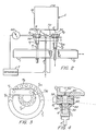
- the O-ring 132 of the cap 120 cooperates with a seating region 136 in a lever arm 138, best seen in Fig. 10.
- the positioning and movement of the lever arm 138 is substantially similar to that described above in connection with the embodiment depicted in Figs. 6A-6C.
- the lever arm 138 of the present embodiment differs in several particulars.
- a substantially flat surface region is provided against which the sealing region 128 of the cap 120 seats when the vial is brought into contact with the lever arm 138, as described more fully below.
- the seating region 136 is defined by an annular, substantially flat surface.
- the seating region 136 surrounds devices (described below) for permitting access to the interior of the vial.
- the seating region 136 can be recessed to provide a shoulder 142 for defining the region in which the cap will be positioned.
- One or more, preferably four, fingers 144A, 144B, 144C, 144D depend downwardly from the level arm 138 for pushing downward the four flaps 126 when they are brought into contact with the sampling region 122 of the cap 120.
- the present embodiment is described in connection with a lever arm mechanism, the embodiment can be used in connection with configurations which do not employ a lever arm, such as the block configuration depicted in Fig. 4, or by providing for direct sealing of the vial to a portion of the cartridge.
- the lever arm 138 can be made of any material capable of providing the desired seal and with sufficient structural integrity to support forces encountered during operation.
- the lever arm 138 is integrally formed from a plastic material, such as by injection molding or the like.
- the vial 154 is at least partially filled with a material to be sampled.
- a cap 120 such as that depicted in Fig 8A, is used to cover the open end of the vial 154, e.g. , using screw threads 155 on the cap flange 157.
- the vial is positioned under the lever arm 138.
- the vial 154 is then moved into contact with the lever arm 138, such as by a plunger, as described above.
- the fingers 144 contact the sampling region 122 of the cap, the fingers 144 force the flaps 124 to deflect downward, as depicted in Fig. 9B, thus providing an opening 156 in the cap.
- the sealing region 128 contacts the seating region 136 of the lever arm 138 to provide a substantial seal surrounding the sample region 122.
- the upward movement of the vial 154 causes the lever arm 138 to rotate about its axis 162, and bring the vial 154 adjacent to the capillary 148 and electrode 152.
- the capillary 148 and electrode 152 are inserted through the conduits 146 of the lever arm 138.
- the capillary 148 and electrode 152 are, in this manner, inserted into the vial 154, as depicted in Fig. 9B, to be partially submerged in the liquid being sampled.
- the plunger is lowered. This allows the spring 80, seen in Fig. 6A, to move the lever arm 18 to its original position, as depicted in Fig. 9A. In this way, the capillary 148 and electrode 152 are withdrawn from the vial 154. Downward movement of the vial 154 causes the vial 154 to move away from the seating area 136 of the lever arm 138, breaking the seal, and permitting the flaps 124 to resiliently deflect upward to substantially their original positions.
- the vial 154 can be repositioned adjacent to the lever arm 138, as described above.
- the vial can be provided either with the original contents of the vial or, after washing and refilling the vial, with a second sample.
- the vial 154 can then be moved upward for sampling the contents of the vial again. Because the sealing region 128 of the cap has not been substantially changed by the first sampling operation, it is effective to provide the desired seal during the second sampling operation. In this manner, the cap and the combination of the cap and vial are reusable.
- the lever arm 138 can be provided without hypodermics or other potentially injurious or sharp objects.
- the lever arm 138 can be made of a single injection molded part, and thus provides for ease of construction and maintenance.
- the present application relates to a covering for a receptacle adapted to be coupled to the opening of the receptacle and including a flexible membrane which may be deflected to allow access to the interior of the receptacle, and to a container comprising the combination of such a covering and receptacle.
- the invention is particularly suited for use with a sampling apparatus as described herein with reference to Figs. I to 7 of the drawings, which apparatus is the subject of co-pending European Patent Application No. 89302491.9 (0339781, published 2 November 1989).
Landscapes
- Health & Medical Sciences (AREA)
- Life Sciences & Earth Sciences (AREA)
- Molecular Biology (AREA)
- Chemical & Material Sciences (AREA)
- Physics & Mathematics (AREA)
- Electrochemistry (AREA)
- Chemical Kinetics & Catalysis (AREA)
- Analytical Chemistry (AREA)
- Biochemistry (AREA)
- General Health & Medical Sciences (AREA)
- General Physics & Mathematics (AREA)
- Immunology (AREA)
- Pathology (AREA)
- Automatic Analysis And Handling Materials Therefor (AREA)
- Sampling And Sample Adjustment (AREA)
Applications Claiming Priority (2)
| Application Number | Priority Date | Filing Date | Title |
|---|---|---|---|
| US31132589A | 1989-02-14 | 1989-02-14 | |
| US311325 | 1989-02-14 |
Publications (2)
| Publication Number | Publication Date |
|---|---|
| EP0383459A2 true EP0383459A2 (de) | 1990-08-22 |
| EP0383459A3 EP0383459A3 (de) | 1991-04-24 |
Family
ID=23206387
Family Applications (1)
| Application Number | Title | Priority Date | Filing Date |
|---|---|---|---|
| EP19900301064 Withdrawn EP0383459A3 (de) | 1989-02-14 | 1990-02-01 | Automatischer Injektor für Kapillare |
Country Status (3)
| Country | Link |
|---|---|
| EP (1) | EP0383459A3 (de) |
| JP (1) | JPH02247554A (de) |
| CA (1) | CA2008494A1 (de) |
Cited By (7)
| Publication number | Priority date | Publication date | Assignee | Title |
|---|---|---|---|---|
| EP0475533A3 (en) * | 1990-09-11 | 1992-12-09 | Lauer Labs B.V. | Method and apparatus for the introduction of a volume of at least one fluid in a tube, in particular suitable for capillary electrophoresis systems and method and apparatus for separating and/or analyzing a fluid material |
| EP0581984A1 (de) * | 1992-08-04 | 1994-02-09 | Hewlett-Packard GmbH | Vorrichtung zur Behandlung von Fiolen in einem "Analyseapparat" |
| EP0581983A1 (de) * | 1992-08-04 | 1994-02-09 | Hewlett-Packard GmbH | Vorrichtung für die Kapillarelektrophorese |
| DE4244825C2 (de) * | 1992-06-06 | 1997-06-05 | Hermann Prof Dr Bauer | Verfahren zur Durchführung einer kapillarelektrophoretischen Bestimmung |
| WO2002079773A1 (fr) * | 2001-03-29 | 2002-10-10 | Hitachi, Ltd. | Dispositif d'electrophorese |
| WO2019241399A1 (en) * | 2018-06-12 | 2019-12-19 | Gmj Technologies, Llc | Liquid handling devices and methods in capillary electrophoresis |
| CN111051846A (zh) * | 2017-09-05 | 2020-04-21 | 霍罗杰克股份有限公司 | 用于自动化标本制备系统的废料排出设备 |
Family Cites Families (4)
| Publication number | Priority date | Publication date | Assignee | Title |
|---|---|---|---|---|
| NL7411605A (nl) * | 1974-09-02 | 1976-03-04 | Philips Nv | Werkwijze voor het automatisch transporteren en injekteren van een vloeistofmonster. |
| US4463616A (en) * | 1982-03-24 | 1984-08-07 | Instrumentation Laboratory Inc. | Sample handling apparatus |
| US4539855A (en) * | 1984-05-03 | 1985-09-10 | Eastman Kodak Company | Apparatus for transferring liquid out of a capped container, and analyzer utilizing same |
| EP0339781A3 (de) * | 1988-04-29 | 1991-09-25 | Beckman Instruments, Inc. | Automatischer Kapillarinjektor |
-
1990
- 1990-01-24 CA CA 2008494 patent/CA2008494A1/en not_active Abandoned
- 1990-02-01 EP EP19900301064 patent/EP0383459A3/de not_active Withdrawn
- 1990-02-14 JP JP2031670A patent/JPH02247554A/ja active Pending
Cited By (10)
| Publication number | Priority date | Publication date | Assignee | Title |
|---|---|---|---|---|
| EP0475533A3 (en) * | 1990-09-11 | 1992-12-09 | Lauer Labs B.V. | Method and apparatus for the introduction of a volume of at least one fluid in a tube, in particular suitable for capillary electrophoresis systems and method and apparatus for separating and/or analyzing a fluid material |
| US5217590A (en) * | 1990-09-11 | 1993-06-08 | Lauer Labs B.V. | Method and apparatus for the introduction of a volume of at least one fluid in a tube in particular suitable for capillary electrophoresis systems and method and apparatus for separating and/or analyzing a fluid material |
| DE4244825C2 (de) * | 1992-06-06 | 1997-06-05 | Hermann Prof Dr Bauer | Verfahren zur Durchführung einer kapillarelektrophoretischen Bestimmung |
| EP0581984A1 (de) * | 1992-08-04 | 1994-02-09 | Hewlett-Packard GmbH | Vorrichtung zur Behandlung von Fiolen in einem "Analyseapparat" |
| EP0581983A1 (de) * | 1992-08-04 | 1994-02-09 | Hewlett-Packard GmbH | Vorrichtung für die Kapillarelektrophorese |
| US5424037A (en) * | 1992-08-04 | 1995-06-13 | Hewlett-Packard Company | Apparatus for handling liquid vials in an analytical device |
| WO2002079773A1 (fr) * | 2001-03-29 | 2002-10-10 | Hitachi, Ltd. | Dispositif d'electrophorese |
| CN111051846A (zh) * | 2017-09-05 | 2020-04-21 | 霍罗杰克股份有限公司 | 用于自动化标本制备系统的废料排出设备 |
| US11768135B2 (en) | 2017-09-05 | 2023-09-26 | Hologic, Inc. | Waste evacuation apparatus for an automated specimen preparation system |
| WO2019241399A1 (en) * | 2018-06-12 | 2019-12-19 | Gmj Technologies, Llc | Liquid handling devices and methods in capillary electrophoresis |
Also Published As
| Publication number | Publication date |
|---|---|
| CA2008494A1 (en) | 1990-08-14 |
| EP0383459A3 (de) | 1991-04-24 |
| JPH02247554A (ja) | 1990-10-03 |
Similar Documents
| Publication | Publication Date | Title |
|---|---|---|
| EP0339781A2 (de) | Automatischer Kapillarinjektor | |
| EP0475533B1 (de) | Verfahren und Vorrichtung zur Einführung mindestens eines Flüssigkeitsvolumens in eine Röhre, insbesondere für kapillare Elektrophoresesysteme und Verfahren und Vorrichtung zur Trennung und/oder Analyse eines fluiden Materials | |
| US6001230A (en) | Automated capillary electrophoresis apparatus | |
| US3680967A (en) | Self-locating sample receptacle having integral identification label | |
| EP0382817B1 (de) | Zugriffssystem für agbeschlossenen behälter | |
| US7374054B2 (en) | Sample vial and vial closure device for use in gas analysis | |
| US5043141A (en) | Injection systems for sample testing for luminometers | |
| EP2210095B1 (de) | Vorrichtungen und Verfahren zur Entnahme und Vorschüttlung perkutaner biologischer Flüssigkeisproben | |
| JPS62100663A (ja) | 小量の液体を処理する装置 | |
| US5384024A (en) | Capillary electrophoresis | |
| US4457846A (en) | Liquid chromatography methods and devices | |
| US20100310426A1 (en) | Reagent cartridge | |
| EP0141148B1 (de) | Automatische Probevorrichtung und Probeverfahren | |
| CN1236434A (zh) | 在加塞的试样管内用于取样和/或注入的装置 | |
| US5351563A (en) | One-way measuring element for analyzing gaseous or liquid samples | |
| AU2007214898A1 (en) | Method and device for withdrawing a volume of liquid by suction, in particular for collecting a sample for analysis by means of a liquid chromatography device | |
| US4823623A (en) | Device for transfer of fluid into sealable vials | |
| EP0581983A1 (de) | Vorrichtung für die Kapillarelektrophorese | |
| CA2008494A1 (en) | Automated capillary injector | |
| US4196618A (en) | Specific volume determining method and apparatus | |
| CN109425573B (zh) | 一种溶液检测装置及检测方法 | |
| US4949858A (en) | Sample bottle and cap therefor | |
| US4461181A (en) | Control for sample volume metering apparatus | |
| US6077713A (en) | Method and apparatus for extracting liquid samples from a closed container | |
| EP0339779A2 (de) | Automatische Vorrichtung für kapillare Elektrophorese |
Legal Events
| Date | Code | Title | Description |
|---|---|---|---|
| PUAI | Public reference made under article 153(3) epc to a published international application that has entered the european phase |
Free format text: ORIGINAL CODE: 0009012 |
|
| AK | Designated contracting states |
Kind code of ref document: A2 Designated state(s): CH DE FR GB IT LI SE |
|
| PUAL | Search report despatched |
Free format text: ORIGINAL CODE: 0009013 |
|
| 17P | Request for examination filed |
Effective date: 19901227 |
|
| AK | Designated contracting states |
Kind code of ref document: A3 Designated state(s): CH DE FR GB IT LI SE |
|
| 17Q | First examination report despatched |
Effective date: 19920731 |
|
| STAA | Information on the status of an ep patent application or granted ep patent |
Free format text: STATUS: THE APPLICATION HAS BEEN WITHDRAWN |
|
| 18W | Application withdrawn |
Withdrawal date: 19930104 |