EP0383508A2 - Verbesserungen an oder in Zusammenhang mit dem Herstellungsverfahren von Schneideeinheiten für rotierende Bohrköpfe - Google Patents
Verbesserungen an oder in Zusammenhang mit dem Herstellungsverfahren von Schneideeinheiten für rotierende Bohrköpfe Download PDFInfo
- Publication number
- EP0383508A2 EP0383508A2 EP90301436A EP90301436A EP0383508A2 EP 0383508 A2 EP0383508 A2 EP 0383508A2 EP 90301436 A EP90301436 A EP 90301436A EP 90301436 A EP90301436 A EP 90301436A EP 0383508 A2 EP0383508 A2 EP 0383508A2
- Authority
- EP
- European Patent Office
- Prior art keywords
- carrier
- backing layer
- rear surface
- bonding
- cutting element
- Prior art date
- Legal status (The legal status is an assumption and is not a legal conclusion. Google has not performed a legal analysis and makes no representation as to the accuracy of the status listed.)
- Granted
Links
Images
Classifications
-
- B—PERFORMING OPERATIONS; TRANSPORTING
- B23—MACHINE TOOLS; METAL-WORKING NOT OTHERWISE PROVIDED FOR
- B23K—SOLDERING OR UNSOLDERING; WELDING; CLADDING OR PLATING BY SOLDERING OR WELDING; CUTTING BY APPLYING HEAT LOCALLY, e.g. FLAME CUTTING; WORKING BY LASER BEAM
- B23K1/00—Soldering, e.g. brazing, or unsoldering
- B23K1/0008—Soldering, e.g. brazing, or unsoldering specially adapted for particular articles or work
-
- B—PERFORMING OPERATIONS; TRANSPORTING
- B23—MACHINE TOOLS; METAL-WORKING NOT OTHERWISE PROVIDED FOR
- B23K—SOLDERING OR UNSOLDERING; WELDING; CLADDING OR PLATING BY SOLDERING OR WELDING; CUTTING BY APPLYING HEAT LOCALLY, e.g. FLAME CUTTING; WORKING BY LASER BEAM
- B23K1/00—Soldering, e.g. brazing, or unsoldering
- B23K1/20—Preliminary treatment of work or areas to be soldered, e.g. in respect of a galvanic coating
-
- B—PERFORMING OPERATIONS; TRANSPORTING
- B23—MACHINE TOOLS; METAL-WORKING NOT OTHERWISE PROVIDED FOR
- B23K—SOLDERING OR UNSOLDERING; WELDING; CLADDING OR PLATING BY SOLDERING OR WELDING; CUTTING BY APPLYING HEAT LOCALLY, e.g. FLAME CUTTING; WORKING BY LASER BEAM
- B23K20/00—Non-electric welding by applying impact or other pressure, with or without the application of heat, e.g. cladding or plating
- B23K20/002—Non-electric welding by applying impact or other pressure, with or without the application of heat, e.g. cladding or plating specially adapted for particular articles or work
-
- B—PERFORMING OPERATIONS; TRANSPORTING
- B23—MACHINE TOOLS; METAL-WORKING NOT OTHERWISE PROVIDED FOR
- B23K—SOLDERING OR UNSOLDERING; WELDING; CLADDING OR PLATING BY SOLDERING OR WELDING; CUTTING BY APPLYING HEAT LOCALLY, e.g. FLAME CUTTING; WORKING BY LASER BEAM
- B23K20/00—Non-electric welding by applying impact or other pressure, with or without the application of heat, e.g. cladding or plating
- B23K20/24—Preliminary treatment
-
- E—FIXED CONSTRUCTIONS
- E21—EARTH OR ROCK DRILLING; MINING
- E21B—EARTH OR ROCK DRILLING; OBTAINING OIL, GAS, WATER, SOLUBLE OR MELTABLE MATERIALS OR A SLURRY OF MINERALS FROM WELLS
- E21B10/00—Drill bits
- E21B10/46—Drill bits characterised by wear resisting parts, e.g. diamond inserts
- E21B10/56—Button-type inserts
- E21B10/567—Button-type inserts with preformed cutting elements mounted on a distinct support, e.g. polycrystalline inserts
- E21B10/5673—Button-type inserts with preformed cutting elements mounted on a distinct support, e.g. polycrystalline inserts having a non planar or non circular cutting face
-
- Y—GENERAL TAGGING OF NEW TECHNOLOGICAL DEVELOPMENTS; GENERAL TAGGING OF CROSS-SECTIONAL TECHNOLOGIES SPANNING OVER SEVERAL SECTIONS OF THE IPC; TECHNICAL SUBJECTS COVERED BY FORMER USPC CROSS-REFERENCE ART COLLECTIONS [XRACs] AND DIGESTS
- Y10—TECHNICAL SUBJECTS COVERED BY FORMER USPC
- Y10S—TECHNICAL SUBJECTS COVERED BY FORMER USPC CROSS-REFERENCE ART COLLECTIONS [XRACs] AND DIGESTS
- Y10S76/00—Metal tools and implements, making
- Y10S76/11—Tungsten and tungsten carbide
-
- Y—GENERAL TAGGING OF NEW TECHNOLOGICAL DEVELOPMENTS; GENERAL TAGGING OF CROSS-SECTIONAL TECHNOLOGIES SPANNING OVER SEVERAL SECTIONS OF THE IPC; TECHNICAL SUBJECTS COVERED BY FORMER USPC CROSS-REFERENCE ART COLLECTIONS [XRACs] AND DIGESTS
- Y10—TECHNICAL SUBJECTS COVERED BY FORMER USPC
- Y10S—TECHNICAL SUBJECTS COVERED BY FORMER USPC CROSS-REFERENCE ART COLLECTIONS [XRACs] AND DIGESTS
- Y10S76/00—Metal tools and implements, making
- Y10S76/12—Diamond tools
Definitions
- the invention relates to rotary drill bits for use in drilling or coring holes in subsurface formations, and particularly to the manufacture of cutter assemblies for use in such drill bits.
- Rotary drill bits of the kind to which the present invention is applicable comprise a bit body having a shank for connection to a drill string and a passage for supplying drilling fluid to the face of the bit, which carries a plurality of cutting elements.
- the cutting elements are so called "preform" cutters comprising a tablet, often circular or part-circular, made out of a thin hard facing layer, usually polycrystalline diamond, bonded to a less hard backing layer, usually cemented tungsten carbide.
- bit body is machined from solid metal, usually steel, or is moulded using a powder metallurgy process in which tungsten carbide powder is infiltrated with metal alloy binder in a furnace so as to form a hard matrix.
- each cutting element is normally mounted on a carrier, such as a stud or post, and the stud or post is then secured within a socket in the bit body.
- a carrier such as a stud or post
- the rear surface of the backing layer is bonded to a surface of the carrier by brazing, although it has also been proposed that other bonding methods may be used, and in particular diffusion bonding.
- the rear surface of the backing layer is substantially flat and is bonded to a corresponding flat surface on the carrier.
- the less hard backing layer normally has a greater coefficient of thermal expansion than the hard facing layer of the cutting element and consequently when the element is heated to the temperature necessary to effect brazing or diffusion bonding there is a differential expansion which causes the cutting element to become dished, with the result that the rear surface of the backing layer is convexly deformed.
- Very high pressure requires to be imparted to the cutting element to flatten it against the flat surface of the carrier and this is difficult to achieve in practice.
- the convex deformity of the rear surface of the backing layer has the result that the spacing between the rear surface and the surface of the carrier is not of constant thickness but is greater nearer the periphery of the cutting element and this may adversely affect the strength of the final bond.
- the present invention sets out to provide methods for overcoming this problem.
- a method of manufacturing a cutter assembly for a rotary drill bit including bonding to a carrier a cutting element which comprises a thin hard facing layer already bonded to a less hard backing layer, the backing layer having a greater coefficient of thermal expansion than the hard facing layer, the method including the step of providing the backing layer with a rear surface, for bonding to the carrier, which is concave at ambient temperature.
- the concave rear surface will tend to flatten as a result of the differential expansion of the diamond layer and backing layer. That is to say, depending on the initial concavity it may become less concave, flat or slightly convex.
- the provision of any concavity in the rear surface of the backing layer is likely to provide some advantage, even in cases where the rear surface is still slightly concavely or convexly deformed at the bonding temperature, since in such cases the deformity may be less than it would be if the rear surface of the backing layer were initially flat.
- the initial concavity of the rear surface of the backing layer is preferably so selected that the rear surface becomes substantially flat at the elevated temperature at which it is bonded to the carrier.
- the cutting element When the cutter assembly is cooled after bonding it to the carrier, the cutting element will tend to try to return to its initial shape and this will have the effect of stressing the bond between the rear surface of the cutting element and the carrier.
- the peripheral edges of the bond will be in compression and this pre-stressed bond may be stronger than the conventional bond between surfaces which are flat at ambient temperature.
- a method of manufacturing a cutter assembly for a rotary drill bit including bonding to a carrier a cutting element which comprises a thin hard facing layer already bonded to a less hard backing layer, the backing layer having a greater coefficient of thermal expansion than the hard facing layer, the method including the step of providing the carrier with a concave surface, and bonding the rear surface of the backing layer of the cutting element to said concave surface of the carrier, whereby said concave surface at least partly accommodates any convex deformation of the rear surface of the backing layer at the elevated temperature at which bonding is carried out.
- the cutting element may be of conventional form, having a flat rear surface, and the convex deformation of the rear surface is then accommodated partly or wholly by the concavity of the surface of the carrier.
- the initial concavity of the surface of the carrier is selected so as substantially to match the convexity of the rear surface of the backing layer at the elevated temperature at which it is bonded to the carrier.
- the methods according to the invention are particularly applicable to the case where the cutting element is diffusion bonded to the carrier, but advantage may also be given in cases where the cutting element is brazed or otherwise bonded to the carrier.
- both the rear surface of the backing layer of the cutting element and the surface on the carrier are concave at ambient temperature.
- the concavity of each will require to be less than in the case where only one surface is initially concave.
- the concavity may be effected by a grinding operation such as the operation commonly used in the art of grinding spherical lenses where a plurality of elements are ground simultaneously using a large part-spherical grinding head.
- Cutter assemblies to which the invention relates are for mounting in the body of a rotary drill bit of the kind first referred to.
- the bit body is formed over the surface thereof with a plurality of sockets and received in each socket is the stud portion of a cutter assembly.
- the cutter assembly is usually shrink-fitted or brazed into its socket.
- the cutter assemblies may be used with bits where the bit body is machined from metal, usually steel, or with matrix-bodied bits which are moulded using a powder metallurgy process, and in this case the sockets are initially moulded in the bit body.
- the construction of such bits is well known and will not be described in further detail.
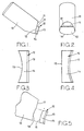
- the cutter assembly comprises a stud or post 10 formed from cemented tungsten carbide.
- the stud is generally cylindrical and circular in cross section and, in use, is received in a socket in the bit body.
- the stud is formed at one end with a flat surface 11 which is inclined at an angle of less than 90° to the longitudinal central axis of the stud.
- a cutting element 12 is bonded to the surface 11 of the stud by diffusion bonding, brazing or other bonding method.
- the cutting element comprises a front hard facing layer 13 of polycrystalline diamond bonded to a thicker backing layer 14 of cemented tungsten carbide.
- the backing layer 14 has a rear surface 15 which is bonded to the surface 11 of the stud 10.
- the cutting element 12 has a part-circular edge 16 opposite a straight edge 17.
- the invention is applicable to other shapes of cutting element and in particular to shapes of cutting element commonly used in the art, such as circular and part-circular cutting elements.
- the illustrated stud or post 10 is by way of example only and any other configuration of carrier may be employed.
- Figure 3 shows the cutting element 12 at ambient temperature. It will be seen that the hard facing layer 13 is flat, in conventional manner, but that the rear surface 15 of the backing layer 14 is spherically concavely curved. As previously described, the concave surface 15 may be formed by a grinding process such as that commonly used in the grinding of concave lenses, appropriate grinding materials being used having regard to the nature of the material of the backing layer 14, namely cemented tungsten carbide.
- two-layer cutting elements of the general kind described are formed by hot pressing a layer of polycrystalline diamond and a layer of powdered tungsten carbide in a press under extremely high pressure and temperature. Accordingly, it may also be possible, as an alternative, to preform the backing layer 14 with the concave surface during the forming process, rather than grinding it subsequently.
- the concavity of the surface 15 is so selected that, at the elevated temperature at which bonding occurs, whether it be diffusion bonding or brazing, the differential expansion effect, due to the difference in coefficients of thermal expansion of the diamond layer and backing layer, causes the rear surface 15 to flatten, as indicated in Figure 4 which shows the cutting element 12 at the temperature of bonding. It will be seen that, as a result of the differential expansion, the diamond layer 13 has adopted a slight concavity. (It should be appreciated that the concavities shown in Figures 3 and 4 are exaggerated for clarity and the actual concavities are considerably smaller).
- the flattened rear surface 15 of the backing layer 14 may be readily and accurately bonded to the flat surface 11 on the stud or post 10.
- the bond between the surfaces 15 and 11 becomes stressed, placing the bond in compression around the periphery of the cutting element, and this may increase the strength of the bond.
- the invention includes within its scope arrangements where the rear surface is still slightly concave or becomes slightly convex at the bonding temperature, since such deformation will still be less than the convex deformity which would otherwise occur if the rear surface were initially flat.
- FIG. 5 illustrates an alternative method according to the invention.
- the rear surface of the cutting element is flat at ambient temperature and it is the surface 11 of the stud 10 which is initially formed with a concavity, as indicated at 18.
- the cutting element 12 may be of conventional configuration, i.e. a tablet of substantially constant thickness.
- the drawing illustrates the deformed shape of the cutting element 12 at the elevated temperature of bonding and it will be seen that, as a result of the differential expansion effect, the rear surface 15 of the backing layer 14 is convexly deformed.
- the initial concavity 18 on the surface 11 of the stud 10 is so selected as substantially to match the convex deformity of the surface 15 so that the two surfaces may be bonded together accurately, by diffusion bonding, brazing or other method.
- the two methods described may be combined.
- the initial concavity of the rear surface 15 is such that it reduces but is not sufficient to eliminate the convex deformation of the surface which occurs upon heating, due to the bi-metallic effect.
- the remaining convexity of the surface is compensated by a corresponding smaller concavity 18 in the surface of the stud 10.
Landscapes
- Engineering & Computer Science (AREA)
- Mechanical Engineering (AREA)
- Life Sciences & Earth Sciences (AREA)
- Mining & Mineral Resources (AREA)
- Geology (AREA)
- Crystallography & Structural Chemistry (AREA)
- Environmental & Geological Engineering (AREA)
- Fluid Mechanics (AREA)
- Physics & Mathematics (AREA)
- Chemical & Material Sciences (AREA)
- General Life Sciences & Earth Sciences (AREA)
- Geochemistry & Mineralogy (AREA)
- Earth Drilling (AREA)
- Drilling Tools (AREA)
Applications Claiming Priority (2)
| Application Number | Priority Date | Filing Date | Title |
|---|---|---|---|
| GB8903542 | 1989-02-16 | ||
| GB8903542A GB2229124B (en) | 1989-02-16 | 1989-02-16 | Improvements in or relating to methods of manufacturing cutter assemblies for rotary drill bits |
Publications (3)
| Publication Number | Publication Date |
|---|---|
| EP0383508A2 true EP0383508A2 (de) | 1990-08-22 |
| EP0383508A3 EP0383508A3 (de) | 1991-01-02 |
| EP0383508B1 EP0383508B1 (de) | 1994-04-20 |
Family
ID=10651803
Family Applications (1)
| Application Number | Title | Priority Date | Filing Date |
|---|---|---|---|
| EP90301436A Expired - Lifetime EP0383508B1 (de) | 1989-02-16 | 1990-02-12 | Verbesserungen an oder in Zusammenhang mit dem Herstellungsverfahren von Schneideeinheiten für rotierende Bohrköpfe |
Country Status (6)
| Country | Link |
|---|---|
| US (1) | US5101691A (de) |
| EP (1) | EP0383508B1 (de) |
| DE (1) | DE69008213T2 (de) |
| GB (1) | GB2229124B (de) |
| IE (1) | IE64127B1 (de) |
| ZA (1) | ZA901113B (de) |
Families Citing this family (6)
| Publication number | Priority date | Publication date | Assignee | Title |
|---|---|---|---|---|
| GB9019914D0 (en) * | 1990-09-12 | 1990-10-24 | Reed Tool Co | Improvements in or relating to the manufacture of cutting structures for rotary drill bits |
| US7000715B2 (en) | 1997-09-08 | 2006-02-21 | Baker Hughes Incorporated | Rotary drill bits exhibiting cutting element placement for optimizing bit torque and cutter life |
| US6672406B2 (en) | 1997-09-08 | 2004-01-06 | Baker Hughes Incorporated | Multi-aggressiveness cuttting face on PDC cutters and method of drilling subterranean formations |
| US6003623A (en) * | 1998-04-24 | 1999-12-21 | Dresser Industries, Inc. | Cutters and bits for terrestrial boring |
| US6823952B1 (en) * | 2000-10-26 | 2004-11-30 | Smith International, Inc. | Structure for polycrystalline diamond insert drill bit body |
| US8540037B2 (en) | 2008-04-30 | 2013-09-24 | Schlumberger Technology Corporation | Layered polycrystalline diamond |
Family Cites Families (6)
| Publication number | Priority date | Publication date | Assignee | Title |
|---|---|---|---|---|
| US4351402A (en) * | 1980-05-27 | 1982-09-28 | Gonzalez Eduardo B | Body structure and nozzle for enhancing the flow of drilling fluid in a rotary drill bit |
| US4660659A (en) * | 1983-02-22 | 1987-04-28 | Nl Industries, Inc. | Drag type drill bit |
| GB8418481D0 (en) * | 1984-07-19 | 1984-08-22 | Nl Petroleum Prod | Rotary drill bits |
| GB8500925D0 (en) * | 1985-01-15 | 1985-02-20 | Nl Petroleum Prod | Cutter assemblies |
| GB8713807D0 (en) * | 1987-06-12 | 1987-07-15 | Nl Petroleum Prod | Cutting structures for rotary drill bits |
| GB8805789D0 (en) * | 1988-03-11 | 1988-04-13 | Reed Tool Co | Improvements in/relating to cutter assemblies for rotary drill bits |
-
1989
- 1989-02-16 GB GB8903542A patent/GB2229124B/en not_active Expired - Fee Related
-
1990
- 1990-02-12 EP EP90301436A patent/EP0383508B1/de not_active Expired - Lifetime
- 1990-02-12 DE DE69008213T patent/DE69008213T2/de not_active Expired - Fee Related
- 1990-02-14 US US07/480,607 patent/US5101691A/en not_active Expired - Fee Related
- 1990-02-14 ZA ZA901113A patent/ZA901113B/xx unknown
- 1990-02-16 IE IE58690A patent/IE64127B1/en not_active IP Right Cessation
Also Published As
| Publication number | Publication date |
|---|---|
| US5101691A (en) | 1992-04-07 |
| EP0383508A3 (de) | 1991-01-02 |
| IE64127B1 (en) | 1995-07-12 |
| GB8903542D0 (en) | 1989-04-05 |
| IE900586L (en) | 1990-08-16 |
| ZA901113B (en) | 1990-11-28 |
| EP0383508B1 (de) | 1994-04-20 |
| DE69008213D1 (de) | 1994-05-26 |
| GB2229124B (en) | 1993-03-31 |
| GB2229124A (en) | 1990-09-19 |
| DE69008213T2 (de) | 1994-10-20 |
Similar Documents
| Publication | Publication Date | Title |
|---|---|---|
| US5533582A (en) | Drill bit cutting element | |
| US4780274A (en) | Manufacture of rotary drill bits | |
| US4109737A (en) | Rotary drill bit | |
| EP0145421B1 (de) | Herstellung von Drehbohrwerkzeugen | |
| EP0295151B1 (de) | Herstellung von Schneideinzelteilen für drehende Bohrköpfe | |
| EP0145423B1 (de) | Drehbohrmeissel und Schneidelement für derartigen Bohrmeissel | |
| US5819862A (en) | Downhole components for use in subsurface drilling | |
| EP0246789A2 (de) | Schneidelement für einen Drehbohrmeissel, Drehbohrmeissel mit derartigem Schneidelement und dessen Herstellungsverfahren | |
| US4699227A (en) | Method of forming cutting structures for rotary drill bits | |
| EP0720879A2 (de) | Verbesserungen an oder bezüglich, mit einem superharten Material bekleideten, Elementen | |
| EP1201873B1 (de) | PDC-Bohrkopf mit spannungsvermindernder Nut | |
| JPH0692045B2 (ja) | 多層多結晶ダイヤモンド固結構造体 | |
| US5060739A (en) | Cutter assemblies for rotary drill bits, and method of manufacturing same | |
| US5101691A (en) | Methods of manufacturing cutter assemblies for rotary drill bits | |
| US4373410A (en) | Method and apparatus for fabricating diamond stud assemblies | |
| EP0193361B1 (de) | Drehbohrmeissel und Verfahren zur Herstellung solcher Meissel | |
| EP0955446B1 (de) | Vorgeformtes Schneidelement | |
| US4781256A (en) | Cutting structures for rotary drill bits | |
| EP0242999A2 (de) | Schneidstrukturen für drehende Bohrköpfe | |
| US20200131855A1 (en) | Polycrystalline diamond compact including at least one mechanically-stressed polycrystalline diamond table and methods of making the same | |
| EP0315221A2 (de) | Drehbohrmeissel und Verfahren zur Herstellung solcher Meissel | |
| IE64021B1 (en) | Improvements in or relating to cutting elements for rotary drill bits | |
| JPS60199190A (ja) | ロ−タリ掘削ビツトのカツテイング要素およびその形成方法 | |
| GB2247855A (en) | Improvements in or relating to the manufacture of cutting structures for rotary drill bits |
Legal Events
| Date | Code | Title | Description |
|---|---|---|---|
| PUAI | Public reference made under article 153(3) epc to a published international application that has entered the european phase |
Free format text: ORIGINAL CODE: 0009012 |
|
| AK | Designated contracting states |
Kind code of ref document: A2 Designated state(s): BE DE FR GB NL |
|
| PUAL | Search report despatched |
Free format text: ORIGINAL CODE: 0009013 |
|
| AK | Designated contracting states |
Kind code of ref document: A3 Designated state(s): BE DE FR GB NL |
|
| 17P | Request for examination filed |
Effective date: 19910618 |
|
| 17Q | First examination report despatched |
Effective date: 19920601 |
|
| RAP1 | Party data changed (applicant data changed or rights of an application transferred) |
Owner name: CAMCO DRILLING GROUP LIMITED |
|
| RBV | Designated contracting states (corrected) |
Designated state(s): BE DE FR NL |
|
| GRAA | (expected) grant |
Free format text: ORIGINAL CODE: 0009210 |
|
| AK | Designated contracting states |
Kind code of ref document: B1 Designated state(s): BE DE FR NL |
|
| REF | Corresponds to: |
Ref document number: 69008213 Country of ref document: DE Date of ref document: 19940526 |
|
| ET | Fr: translation filed | ||
| PGFP | Annual fee paid to national office [announced via postgrant information from national office to epo] |
Ref country code: DE Payment date: 19950209 Year of fee payment: 6 |
|
| PLBE | No opposition filed within time limit |
Free format text: ORIGINAL CODE: 0009261 |
|
| STAA | Information on the status of an ep patent application or granted ep patent |
Free format text: STATUS: NO OPPOSITION FILED WITHIN TIME LIMIT |
|
| PGFP | Annual fee paid to national office [announced via postgrant information from national office to epo] |
Ref country code: BE Payment date: 19950410 Year of fee payment: 6 |
|
| 26N | No opposition filed | ||
| PG25 | Lapsed in a contracting state [announced via postgrant information from national office to epo] |
Ref country code: NL Effective date: 19950901 |
|
| PG25 | Lapsed in a contracting state [announced via postgrant information from national office to epo] |
Ref country code: FR Effective date: 19951031 |
|
| NLV4 | Nl: lapsed or anulled due to non-payment of the annual fee |
Effective date: 19950901 |
|
| REG | Reference to a national code |
Ref country code: FR Ref legal event code: ST |
|
| PG25 | Lapsed in a contracting state [announced via postgrant information from national office to epo] |
Ref country code: BE Effective date: 19960228 |
|
| BERE | Be: lapsed |
Owner name: CAMCO DRILLING GROUP LTD Effective date: 19960228 |
|
| PG25 | Lapsed in a contracting state [announced via postgrant information from national office to epo] |
Ref country code: DE Effective date: 19961101 |