EP0383542A1 - Cric pour lever une charge - Google Patents
Cric pour lever une charge Download PDFInfo
- Publication number
- EP0383542A1 EP0383542A1 EP90301514A EP90301514A EP0383542A1 EP 0383542 A1 EP0383542 A1 EP 0383542A1 EP 90301514 A EP90301514 A EP 90301514A EP 90301514 A EP90301514 A EP 90301514A EP 0383542 A1 EP0383542 A1 EP 0383542A1
- Authority
- EP
- European Patent Office
- Prior art keywords
- load
- bearing
- base
- arm
- carried
- Prior art date
- Legal status (The legal status is an assumption and is not a legal conclusion. Google has not performed a legal analysis and makes no representation as to the accuracy of the status listed.)
- Withdrawn
Links
Images

Classifications
-
- B—PERFORMING OPERATIONS; TRANSPORTING
- B66—HOISTING; LIFTING; HAULING
- B66F—HOISTING, LIFTING, HAULING OR PUSHING, NOT OTHERWISE PROVIDED FOR, e.g. DEVICES WHICH APPLY A LIFTING OR PUSHING FORCE DIRECTLY TO THE SURFACE OF A LOAD
- B66F3/00—Devices, e.g. jacks, adapted for uninterrupted lifting of loads
- B66F3/08—Devices, e.g. jacks, adapted for uninterrupted lifting of loads screw operated
- B66F3/12—Devices, e.g. jacks, adapted for uninterrupted lifting of loads screw operated comprising toggle levers
Definitions
- This invention is concerned with improvements in or relating to load-lifting jacks and especially to such jacks for use in jacking vehicles e.g. for changing wheels.
- Load-lifting jacks of various constructions have been proposed in the past.
- jacks made by the applicant company which are sometimes referred to as cantilever-type jacks.
- jacks of this general type are shown: both of these specifications describe a jack in which a load-bearing arm is moved by a lead screw through a nut (to which the arm is pivotally connected) which itself is moved lengthwise of the lead screw by rotation of the screw.
- a link is pivotally connected to the load-bearing arm at a position intermediate the point at which the arm is pivotally connected to the nut and a load-engaging portion of the arm, the link also being pivotally connected to a ground-engaging member.
- the lead screw in both instances, is rotatably mounted on the ground-engaging member by means of a thrust bearing carried by the member at a position remote from the position at which the link is pivotted, the nut being disposed between the thrust bearing and the pivot for the link.
- the invention may be considered to provide a load-lifting jack comprising a ground-engaging frame, link means mounted on the ground-engaging frame by first pivot means and connected to a load-bearing arm by second pivot means positioned intermediate a load-engaging portion of the arm and third pivot means by which the arm is connected to a nut which is in threaded engagement with a lead screw the lead screw being mounted for rotation in a load-carrying bearing mounted on the ground-engaging frame so that the bearing is closer to said first pivot means than is the nut.
- the ground-engaging frame of a jack in accordance with the invention comprises a base on which the link means is pivotted and the load-carrying bearing is carried by a bearing support suitably carried by one or more brackets projecting upwardly from the base.
- the bearing is preferably carried by the support at a position intermediate the nut and said first pivot means.
- the link means comprises two links symmetrically positioned at either side of the arm and the first pivot means comprises coaxial pivots, conveniently carried by spaced brackets upwardly projecting from the base.
- the preferred bearing support is of a generally U-shaped configuration, and comprises two limbs mounted on the base and a transverse connecting portion by which the limbs are connected remote from the base, the bearing being carried by the connecting portion.
- the limbs suitably are encompassed by the links of the link means and are mounted on the pivots for the links.
- Each of the brackets of the preferred jack has an associated link carried by its pivot, the link being disposed outwardly of the bracket and the limb of the bearing support inwardly thereof.
- the lead screw is also supported at a position remote from the load-carrying bearing by a part of the ground-engaging member to stabilise it.
- the support provided is sufficient to permit rotation of the lead screw and to provide sufficient restraint against movement transversely to the axis of the lead screw but no, or substantially no load is transferred to the part in a direction axially of the screw.
- Means is provided for rotating the lead screw to operate the jack and this suitably comprises a portion of the lead screw projecting beyond said part adapted to be engaged by an operating member, for example a ratchet spanner, whereby to rotate the lead screw.
- the illustrative load-lifting jack is suitable for use in jacking up vehicles for example for changing wheels and is especially intended for use with light goods vehicles.
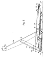
- the illustrative jack comprises a ground-engaging frame comprising a base 10, channel section main frame members 12 each having a first end portion secured to the base 10, the members 12 each having two portions 14 converging from the base to parallel portions 16.
- the ground-engaging frame further comprises a foot 18 interconnecting the parallel portions 16, a tie member 20 disposed between the foot 18 and the base 10 also interconnecting the parallel portions 16 and a transverse support portion provided by an end plate 22 inter-connecting the parallel end portions 16 at the end portion remote from the base 10.
- Two channel section links 24 are mounted for pivotal movement about first pivot means, namely coaxial pivots 26 carried by brackets 28 projecting upwardly from the base 10.
- the base 10 comprises a body part pressed from a metal sheet and has two spaced portions cut from the metal sheet and bent upwardly to provide part of the bracket 28 leaving openings 30 in the body part.
- a cover plate 32 is spot welded beneath the body part of the base 10 and has two ears upstanding through the openings 30 adjacent the upwardly bent portions of the body part of the base plate the ears and the upwardly bent portions together providing the brackets 28.
- a lead screw 46 is mounted for rotation in the load-carrying bearing and comprises a headed end portion 48 adapted to engage the thrust collar 44 of the bearing whereby to transmit load applied by the lead screw 46 through the bearing to the bearing support 34.
- the lead screw 46 is supported at a position remote from the bearing by the end plate 22 of the ground-engaging frame to stabilise the screw 46.
- a knurled disc 50 is secured to the lead screw outwardly of the end plate 22 so that the lead screw 46 can be readily rotated by hand using the knurled disc 50 when there is little or no load on the jack.
- the lead screw 46 may also be rotated by an operating member (not shown), for example a suitable ratchet spanner or handle: the end portion of the lead screw outwardly of the knurled disc 50 is provided with drive means 52 with which such an operating member may be brought into engagement and used to rotate the lead screw.
- an operating member for example a suitable ratchet spanner or handle: the end portion of the lead screw outwardly of the knurled disc 50 is provided with drive means 52 with which such an operating member may be brought into engagement and used to rotate the lead screw.
- the illustrative jack further comprises a load-carrying arm 54 comprising a load-engaging portion, namely a top step 56 at one end portion of the arm.
- the top step is connected to an end portion of the arm 54 by a pivot pin 58 and includes a peg 60 adapted to engage a vehicle body whereby to position the top step in suitable location relative to a jacking point of the vehicle body.
- the links 24 are connected by second pivot means, namely a pivot 68, at end portions remote from the pivots 26, to the load-bearing arm 54.
- the pivot 68 is positioned intermediate the top step 56 and third pivot means, namely pivot pins 62 by which an end portion of the load-bearing arm 54 opposite the top step 56 is connected to a nut 64 which is in threaded engagement with the lead screw 46. Collars 66 retain the load-bearing arm 54 in engagement with the pivot pins 62 carried by the nut 64.
- the base 10 and foot 18 of the ground-engaging member are placed on the ground G and the lead screw 46 rotated by means of the knurled disc 50 to raise the load-bearing arm 54 from a retracted position (in which it is shown in full line in Figure 2) to a suitable extended position in engagement with a jacking point of a vehicle which is to be raised by the jack.
- the load-bearing arm 54 is further raised using a suitable operating member applied to the portion 52.
- the load is distributed over a substantially greater area than is the case where the load is transferred through a thrust bearing to an end plate remote from the region at which the links are pivotted.
- the change in construction not only reduces the possibility that distortion of the jack (especially the end plate) will occur under load but also enables the use of a lighter construction as less reinforcement is required.
- the illustrative jack is believed to be not only of more efficient construction and less liable to damage than the previously known jacks referred to above but also to be relatively cheap to manufacture.
Landscapes
- Life Sciences & Earth Sciences (AREA)
- Engineering & Computer Science (AREA)
- Geology (AREA)
- Mechanical Engineering (AREA)
- Structural Engineering (AREA)
- Vehicle Cleaning, Maintenance, Repair, Refitting, And Outriggers (AREA)
- Jib Cranes (AREA)
Applications Claiming Priority (2)
| Application Number | Priority Date | Filing Date | Title |
|---|---|---|---|
| GB8903495A GB2228249A (en) | 1989-02-16 | 1989-02-16 | Load-lifting jack. |
| GB8903495 | 1989-02-16 |
Publications (1)
| Publication Number | Publication Date |
|---|---|
| EP0383542A1 true EP0383542A1 (fr) | 1990-08-22 |
Family
ID=10651776
Family Applications (1)
| Application Number | Title | Priority Date | Filing Date |
|---|---|---|---|
| EP90301514A Withdrawn EP0383542A1 (fr) | 1989-02-16 | 1990-02-13 | Cric pour lever une charge |
Country Status (2)
| Country | Link |
|---|---|
| EP (1) | EP0383542A1 (fr) |
| GB (1) | GB2228249A (fr) |
Families Citing this family (2)
| Publication number | Priority date | Publication date | Assignee | Title |
|---|---|---|---|---|
| US5346180A (en) * | 1993-06-10 | 1994-09-13 | Seeburn Metal Products Limited | Pantograph jack |
| US5449149A (en) * | 1994-05-19 | 1995-09-12 | Ventra Group, Inc. | Pantograph jack |
Citations (8)
| Publication number | Priority date | Publication date | Assignee | Title |
|---|---|---|---|---|
| US2469048A (en) * | 1946-06-24 | 1949-05-03 | Walker Mfg Company Of Wisconsi | Lifting mechanism |
| GB903079A (en) * | 1958-10-25 | 1962-08-09 | Metallifacture Ltd | Improvements in or relating to load lifting jacks |
| GB980024A (en) * | 1963-01-05 | 1965-01-13 | Metallifacture Ltd | Improvements in or relating to load lifting jacks |
| GB1082067A (en) * | 1965-02-26 | 1967-09-06 | Metallifacture Ltd | Improvements in or relating to load lifting jacks |
| CH483360A (de) * | 1968-04-11 | 1969-12-31 | Tangyes Ltd | Wagenheber |
| GB1227715A (fr) * | 1969-01-17 | 1971-04-07 | ||
| GB1322426A (en) * | 1970-07-03 | 1973-07-04 | Aisin Seiki | Load lifting jacks |
| EP0226695A1 (fr) * | 1985-12-18 | 1987-07-01 | Ford-Werke Aktiengesellschaft | Cric pour véhicules à moteur |
Family Cites Families (2)
| Publication number | Priority date | Publication date | Assignee | Title |
|---|---|---|---|---|
| US3938780A (en) * | 1974-02-21 | 1976-02-17 | Hauptman Murray L | Automobile chassis jack |
| US4589630A (en) * | 1985-03-13 | 1986-05-20 | Safe-T-Jack, Inc. | Dual automobile jack for consumer use |
-
1989
- 1989-02-16 GB GB8903495A patent/GB2228249A/en not_active Withdrawn
-
1990
- 1990-02-13 EP EP90301514A patent/EP0383542A1/fr not_active Withdrawn
Patent Citations (8)
| Publication number | Priority date | Publication date | Assignee | Title |
|---|---|---|---|---|
| US2469048A (en) * | 1946-06-24 | 1949-05-03 | Walker Mfg Company Of Wisconsi | Lifting mechanism |
| GB903079A (en) * | 1958-10-25 | 1962-08-09 | Metallifacture Ltd | Improvements in or relating to load lifting jacks |
| GB980024A (en) * | 1963-01-05 | 1965-01-13 | Metallifacture Ltd | Improvements in or relating to load lifting jacks |
| GB1082067A (en) * | 1965-02-26 | 1967-09-06 | Metallifacture Ltd | Improvements in or relating to load lifting jacks |
| CH483360A (de) * | 1968-04-11 | 1969-12-31 | Tangyes Ltd | Wagenheber |
| GB1227715A (fr) * | 1969-01-17 | 1971-04-07 | ||
| GB1322426A (en) * | 1970-07-03 | 1973-07-04 | Aisin Seiki | Load lifting jacks |
| EP0226695A1 (fr) * | 1985-12-18 | 1987-07-01 | Ford-Werke Aktiengesellschaft | Cric pour véhicules à moteur |
Also Published As
| Publication number | Publication date |
|---|---|
| GB8903495D0 (en) | 1989-04-05 |
| GB2228249A (en) | 1990-08-22 |
Similar Documents
| Publication | Publication Date | Title |
|---|---|---|
| US4655466A (en) | Cart | |
| US4549721A (en) | Portable jack for small tractors and like vehicles | |
| US4765595A (en) | Scissor jack | |
| US3989225A (en) | Vehicle lifting jack | |
| US5549437A (en) | Fork lift truck loading mechanism | |
| US6070856A (en) | Car jack | |
| US4415300A (en) | Transporter-unloader for large cylindrical hay bales | |
| EP0151154B1 (fr) | Cercle horizontal | |
| US4690378A (en) | Vehicle jack | |
| EP0138818B1 (fr) | Plate-forme de chargement et dispositif de montage combines pour un hayon elevateur et plate-forme et organe de support pour une telle combinaison | |
| CN212049253U (zh) | 一种举升装置及自动导引运输车 | |
| US3762590A (en) | Material lifting and transporting vehicle | |
| GB2228249A (en) | Load-lifting jack. | |
| EP2014605A1 (fr) | Dispositif monte-charge et plate-forme pour dispositif monte-charge | |
| EP0060064A2 (fr) | Cric pour le levage par le côté d'automobiles à coque autoportante | |
| EP1195470A1 (fr) | Machine de terrassement | |
| EP0396233A1 (fr) | Cric de véhicule | |
| EP0040542A1 (fr) | Remorque à col de cygne repliable | |
| AU606074B2 (en) | Multi-function wrecker lift | |
| US4893785A (en) | Lifting device | |
| EP0773186A2 (fr) | Tourillon pour l'utilisation avec une grue à parallélogramme | |
| WO2003043850A1 (fr) | Prolongement arriere pivotant | |
| WO1989002867A1 (fr) | Dispositif de presentation de vehicules | |
| EP0543791A1 (fr) | Véhicule élévateur pour le stockage de charges | |
| EP0321164B1 (fr) | Cric de véhicule |
Legal Events
| Date | Code | Title | Description |
|---|---|---|---|
| PUAI | Public reference made under article 153(3) epc to a published international application that has entered the european phase |
Free format text: ORIGINAL CODE: 0009012 |
|
| AK | Designated contracting states |
Kind code of ref document: A1 Designated state(s): DE ES FR GB IT SE |
|
| STAA | Information on the status of an ep patent application or granted ep patent |
Free format text: STATUS: THE APPLICATION IS DEEMED TO BE WITHDRAWN |
|
| 18D | Application deemed to be withdrawn |
Effective date: 19910223 |