EP0383581A2 - Matériaux de revêtement intérieur pour un tube à rayons cathodiques - Google Patents
Matériaux de revêtement intérieur pour un tube à rayons cathodiques Download PDFInfo
- Publication number
- EP0383581A2 EP0383581A2 EP90301588A EP90301588A EP0383581A2 EP 0383581 A2 EP0383581 A2 EP 0383581A2 EP 90301588 A EP90301588 A EP 90301588A EP 90301588 A EP90301588 A EP 90301588A EP 0383581 A2 EP0383581 A2 EP 0383581A2
- Authority
- EP
- European Patent Office
- Prior art keywords
- coating
- silica
- internal coating
- range
- cathode ray
- Prior art date
- Legal status (The legal status is an assumption and is not a legal conclusion. Google has not performed a legal analysis and makes no representation as to the accuracy of the status listed.)
- Withdrawn
Links
Images


Classifications
-
- H—ELECTRICITY
- H01—ELECTRIC ELEMENTS
- H01J—ELECTRIC DISCHARGE TUBES OR DISCHARGE LAMPS
- H01J29/00—Details of cathode-ray tubes or of electron-beam tubes of the types covered by group H01J31/00
- H01J29/86—Vessels; Containers; Vacuum locks
- H01J29/88—Vessels; Containers; Vacuum locks provided with coatings on the walls thereof; Selection of materials for the coatings
-
- H—ELECTRICITY
- H01—ELECTRIC ELEMENTS
- H01J—ELECTRIC DISCHARGE TUBES OR DISCHARGE LAMPS
- H01J9/00—Apparatus or processes specially adapted for the manufacture, installation, removal, maintenance of electric discharge tubes, discharge lamps, or parts thereof; Recovery of material from discharge tubes or lamps
- H01J9/20—Manufacture of screens on or from which an image or pattern is formed, picked up, converted or stored; Applying coatings to the vessel
-
- H—ELECTRICITY
- H01—ELECTRIC ELEMENTS
- H01J—ELECTRIC DISCHARGE TUBES OR DISCHARGE LAMPS
- H01J2229/00—Details of cathode ray tubes or electron beam tubes
- H01J2229/88—Coatings
- H01J2229/882—Coatings having particular electrical resistive or conductive properties
Definitions
- This invention broadly relates to internal coating materials for a cathode ray tube which are characterized by the fact that, in order to increase the electric resistivity of the internal coating, a non-conductive pigment which is predominantly comprised of silica powders for instance made by fusing and spraying with the average primary particle size of 0.05 to 3, or more broadly 0.02 to 15 micron on average, and the maximum primary particle size at 20 micron (or more preferably at 15 micron) are used together with electrically conductive graphite powders at the mixing ratio from 0.1 to 15.
- a non-conductive pigment which is predominantly comprised of silica powders for instance made by fusing and spraying with the average primary particle size of 0.05 to 3, or more broadly 0.02 to 15 micron on average, and the maximum primary particle size at 20 micron (or more preferably at 15 micron) are used together with electrically conductive graphite powders at the mixing ratio from 0.1 to 15.
- the invention also relates to such internal coating materials in which silica powders are used which have been fused in the process of flame spraying, along with other optional mineral products of similar chemical compositions, and/or optional artificial materials with similar chemical compositions which are powdered or in finely particulated form.
- This invention also relates to internal coating compositions of the type described above in which one of, or more than one of, the non-conductive materials, such as iron oxide, titanium oxide, chromium oxide, aluminum oxide, and silicon carbide are selectively used together with the silica powder.
- the non-conductive materials such as iron oxide, titanium oxide, chromium oxide, aluminum oxide, and silicon carbide are selectively used together with the silica powder.
- the internal coating materials described herein have an electric resistance, broadly stated from 0.075 to 50,000 ohm cm, preferably from 0.15 to 20,000 ohm cm, or most preferably from 1 to 1,000 ohm cm.
- Internal coating materials referred to herein are to be applied over a part of, or the entire internal surface of, a funnel of a TV cathode ray tube, at the thickness of 3 to 50 micron, or more preferably 8 to 30 micron.
- This invention is related to the internal coating materials to be applied over the cathode ray tubes including TV cathode ray tubes.
- an electrically conductive coating is applied on an internal surface of a funnel of a black and white TV(or a color TV) cathode ray tube which is mainly composed of graphite powders and sodium or potassium water glass.
- This coating serves to accelerate electrons by applying a high electric voltage, to increase the clarity color by capturing secondary electrons which are generated from a shadow mask etc. and for other functions.
- the required resistivity is 0.03 to 0.3 ohm cm and such a coating is called a normal resistance internal coating.
- a high resistance internal coating is required and is widely used, such that it can suppress the peak value of a surge current when an unexpectedly great electric current flows through the internal coating.
- a stable and non-conductive inorganic pigment is used together with graphite powders to make such an internal coating material.
- Such pigments are for example titanium oxide, iron oxide, zinc oxide, etc.
- U.S. Patent 4,272,701(GTE Products Corporation) which explains the relation between the heat of formation and chemical stability of chromium oxide, aluminum oxide and titanium oxide.
- Various works have been reported which also discussed the possibility of using nickel oxide, manganese oxide, magnesium oxide, cobalt oxide and aluminum oxide.
- the oxides referred to above are relatively thermodynamically unstable being reduced from a normal oxidation state to a lower oxidation state resulting in the generation of oxygen, followed by the generation of carbon monoxide as the result of the reaction of oxygen and graphite powders. It goes without saying these gases deteriorate the degree of vacuum and cause a wasteful consumption of barium.
- the internal coating materials for a cathode ray tube which are produced by using silica powders with the average primary particle size broadly between 0.02 and 15 micron(preferably between 0.05 and 3 micron) and the maximum primary particle size less than 20 micron, broadly stated, and preferably less than 15 micron; together with the electrically conductive graphite powders at the mixing weight ratio of 0.1 to 15; and preferably mixing weight ratio(i.e., pigment ratio) of silica to graphite of from about 1 to about 10.
- the use of the ratio of silica to graphite in the range from 1.5 to 4.0 generally results in the electric resistivity of about 2.0 ohm cm to about 11 ohm cm.
- This invention is also to include a formulation in which a part of the silica powders is replaced by other metallic oxides, or other non-conductive pigments, and which has the above range of resistivity.
- Such electrically conducting internal coating dispersions as disclosed herein can be applied not only by brush coating, but also by sponge, spray, spray followed by flow, flow, or dip coating methods.
- silica powders work was carried out on silica powders and a range of electrically resistive internal coatings were prepared and evaluated. No internal coatings with satisfactory properties were obtained by use of commonly known colloidal silica, silica powders made either by the sol or the gel method both based on the wet process, nor silica powders produced as a biproduct of the manufacture of metallic silicon. However it was discovered that an internal coating with excellent properties was obtainable when silica powders having a specified particle size range, and special shape and surface nature were employed.
- the silica powder is comprised primarily of silica(but minor amounts of other minerals of similar chemical composition or artificial materials of similar chemical composition may also be present).
- the silica powders are fused during the process of flame spraying(and this is what is meant by the terminology "fused and sprayed" as is sometimes used herein).
- the silica powders are generally spherical, or of hexahedron shape, or similar shapes, having the average size of the primary particle broadly of 0.02 to 15 micron(preferably 0.05 to 3 micron) average particle size, and the maximum primary particle size of 20 micron.
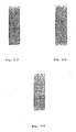
- Fig. 2-1 to Fig. 2-11 show the tapes after the tape test, by use of an adhesive tape conducted by the normal tape test practice, of the internal coatings for a cathode ray tube comprising graphite powders and various types of silica powders as non-conductive metallic oxide. These coatings were applied over a glass panel by a brush, dried at 150°C for 30 minutes and then baked at 430°C for 1 hour before the tape test.
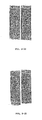
- Fig. 2-12(Photo 12) shows the tape of the tape test of the internal coating of the present invention(Formulation 9) applied over a panel and Dag5610(a normal resistance internal coating of Acheson company) which was applied after Formulation 9 with a small overlapping area.
- Fig. 2-13(Photo 13) shows the tape after the tape test of the commercially existing high resistance internal coating comprising a metallic oxide applied over a glass panel and the commercially existing normal resistance internal coating applied with a small overlapping are in the same way as before. (See further discussion in Working Example 3).
- Such internal coatings or dispersions are usually produced by charging water glass, that is, an aqueous solution of a silicate of an alkali metal(especially sodium silicate or potassium silicate), graphite powers, non-conductive pigments, an organic thickener such as PVA and CMC and a small amount of a dispersing agent such as sodium lignin sulfonate into a pebble mill, and by rolling it for a required period of time.
- silica powders as described herein over other known non-conductive pigments are as follows. It is larger than many commonly used metallic oxide powders. Therefore the statistical chances are much less for such powders to be detached accidentally, to fly up inside the funnel, and subsequently to cause the short circuit of the electrodes of an electron gun. The reduction reaction of other metallic oxide is relatively likely to take place due to the relatively small heat of reaction.
- the materials covered by the present invention especially silica powders made by fusing and spraying will provide a coating having an electric resistivity continuously changing over a wide range, within a workable viscosity value, by altering the pigment ratio of silica to graphite.
- the tape test results are also very beneficial in the above range of resistivity. It is widely practiced in the industry to apply both a normal resistance internal coating and a high resistance internal coating in the front and rear areas respectively, of a cathode ray tube, for the purpose of controlling the overall resistance of the internal coating.
- silica powders produced by fusing and spraying as described in this invention it will become possible to coat the entire funnel surface with one kind of coating whose resistivity is controlled to a desired value by selecting a specific mixing ratio(pigment ratio) of the silica powders to graphite.
- silica powders employed in the working examples are as follows. Average diameter of primary particle (micron) 1) Colloidal silica Nissan Chemical Co. Snowtex ZL 0.1 2) Colloidal silica Nissan Chemical Co. Snowtex C 0.01 - 0.02 3) Wet process silica Nippon Silica Co. E 150K 1 4) Wet process silica Nippon Silica Co. E 75 1 5) Wet process (Gel process) silica Fuji Davidson Co. Cylloid 66 0.5 6) Silica, by-product of metallic silicon production ELKEM Materials A/S Microsilica 580-V 4 7) Powdered silica(silica rock mechanically powdered) Tatsumori Co.
- Crystallite VX-X 1 Fused and powdered silica rock (silica rock fused and powdered after cooling) Tatsumori Co.
- Fuse FF 2 Fused and spray-powdered silica i.e., fused in the process of flame spraying Micron Co. Harimic S-OF 2.3
- Coating dispersions were manufactured as below. Manufacturing method 1 Weight % Graphite powders 5.5 Silica powders 12.7 CMC 1.0 Potassium water glass(28% Solids) 37.7 Deionized water 43.1 100.0 The above raw materials were charged into a pebble mill and rolled for 15 to 25 hours. Following is the evaluation method for the coating dispersions prepared.
- the electric resistivity can be varied by changing the pigment ratio of silica powders(manufactured by fusing and spraying) to graphite powders.
- the total weight percent of silica powders and graphite is 18.2%.
- a series of experiments were carried out by changing the ratio of silica powder to graphite but by maintaining the total weight percent constant at 18.2%.
- Photo 12 shows the tape of the tape test of Formulation 9 or the high resistance internal coating of the present invention and Dag56lo(a normal resistance internal coating) of Acheson Company successively applied.
- Photo 13 shows the tape of a prior existing high resistance internal coating containing a metallic oxide and an existing normal resistance internal coating successively applied.
- the area of the tapes indicating the area of a high resistance internal coating indicates the superior property of Formulation 9 of the present invention.
- the tape is pressed against the normal resistance internal coating in the overlapping area.
- the tape test of Dag5610, a normal resistance internal coating of Acheson Company appears much better than that of the existing normal resistance internal coating when corresponding high resistance internal coatings are underlying.
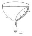
- the elements 1, 2, 3, and 4 are a funnel, a glass wall, a normal resistance internal coating and a high resistance internal coating, respectively.
- a particularly preferred coating composition in accordance with the invention is as follows: Weight % Electrically conductive graphite powder 5.5 (preferably synthetic graphite) (having a particle size within the range of about 1 to about 7 microns) Silica powder 12.7 (fused and sprayed) (Harimic S-OF 2) CMC 1.0 Potassium water glass 37.7 (28% solids) Water 43.1 (preferably deionized) 100.0 This coating composition is prepared as described in manufacturing method #1 above.
- the properties of the internal coating material for cathode ray tubes as described in this invention should be generally as follows.
- the electric resistance of the coating should broadly be within the range of about 0.075 to about 50,000 ohm cm; and preferably within the range of about 0.15 to about 20,000 ohm cm; and best results have been obtained when the electric resistance of the coating is maintained within the range of about 1 to about 1,000 ohm cm.
- the thickness for the applied coatings should generally be within the range of about 3 to about 50 microns thickness for the coating, and preferably within the range of about 8 to about 30 microns thickness for the coating.
- the silica powder should have an average particle size within the range of about 0.02 to about 15 microns and preferably within the range of about 0.05 to about 3 microns.
- the maximum primary particle size for the silica powders should be about 20 microns or less, and preferably less than about 15 microns.
- the viscosity range for the coating composition prior to application should be within the range of about 270 to about 850 cps.
- the graphite powder should preferably be a synthetic graphite, or a purified natural graphite can also be used.
- the graphite powder should have a particle size, broadly stated within the range of about 0.1 to about 30 microns, and preferably within the range of about 1 to about 7 microns.
Landscapes
- Engineering & Computer Science (AREA)
- Manufacturing & Machinery (AREA)
- Vessels, Lead-In Wires, Accessory Apparatuses For Cathode-Ray Tubes (AREA)
- Paints Or Removers (AREA)
- Conductive Materials (AREA)
Applications Claiming Priority (2)
| Application Number | Priority Date | Filing Date | Title |
|---|---|---|---|
| JP35437/89 | 1989-02-15 | ||
| JP1035437A JPH02214784A (ja) | 1989-02-15 | 1989-02-15 | 陰極線管用内装コーティング剤組成物 |
Publications (2)
| Publication Number | Publication Date |
|---|---|
| EP0383581A2 true EP0383581A2 (fr) | 1990-08-22 |
| EP0383581A3 EP0383581A3 (fr) | 1991-07-24 |
Family
ID=12441825
Family Applications (1)
| Application Number | Title | Priority Date | Filing Date |
|---|---|---|---|
| EP19900301588 Withdrawn EP0383581A3 (fr) | 1989-02-15 | 1990-02-14 | Matériaux de revêtement intérieur pour un tube à rayons cathodiques |
Country Status (4)
| Country | Link |
|---|---|
| US (1) | US5160375A (fr) |
| EP (1) | EP0383581A3 (fr) |
| JP (1) | JPH02214784A (fr) |
| BR (1) | BR9000681A (fr) |
Families Citing this family (11)
| Publication number | Priority date | Publication date | Assignee | Title |
|---|---|---|---|---|
| EP0533030B1 (fr) * | 1991-09-20 | 1995-06-21 | Hitachi, Ltd. | Procédé et dispositif pour fabrication d'une pellicule antireflets pour tubes à rayons cathodique |
| US6303181B1 (en) | 1993-05-17 | 2001-10-16 | Electrochemicals Inc. | Direct metallization process employing a cationic conditioner and a binder |
| US5725807A (en) | 1993-05-17 | 1998-03-10 | Electrochemicals Inc. | Carbon containing composition for electroplating |
| US6710259B2 (en) | 1993-05-17 | 2004-03-23 | Electrochemicals, Inc. | Printed wiring boards and methods for making them |
| US6171468B1 (en) * | 1993-05-17 | 2001-01-09 | Electrochemicals Inc. | Direct metallization process |
| US5667729A (en) * | 1995-04-04 | 1997-09-16 | Hitachi Powdered Metals Co., Ltd. | Coating material for inner coat of cathode-ray tube |
| JP2000268717A (ja) * | 1999-03-19 | 2000-09-29 | Hitachi Ltd | 陰極線管およびその製造方法 |
| JP3578971B2 (ja) * | 2000-05-17 | 2004-10-20 | 日立粉末冶金株式会社 | 陰極線管用内装塗料 |
| JP3509778B2 (ja) * | 2001-06-01 | 2004-03-22 | ソニー株式会社 | 陰極線管及び陰極線管の製造方法 |
| US6819040B2 (en) * | 2003-02-27 | 2004-11-16 | Thomson Licensing S. A. | Cathode ray tube having an internal neutral density filter |
| US7264752B2 (en) * | 2003-08-29 | 2007-09-04 | Xerox Corporation | Conductive coatings for corona generating devices |
Family Cites Families (14)
| Publication number | Priority date | Publication date | Assignee | Title |
|---|---|---|---|---|
| US2951773A (en) * | 1955-02-12 | 1960-09-06 | Philips Corp | Method of coating electrical discharge tubes |
| DE1639202B2 (de) * | 1965-06-15 | 1971-04-29 | Suspension und verfahren zum herstellen eines leicht entgas baren haftfesten elektrisch leitenden ueberzuges in elektro nenroehren | |
| NL145095B (nl) * | 1965-06-15 | 1975-02-17 | Acheson Ind Inc | Werkwijze voor het bereiden van een preparaat voor het vormen van een elektrisch geleidende bekledingslaag, alsmede werkwijze voor het vormen van deze elektrisch geleidende bekledingslaag op drageroppervlakken en voorwerp met aan het oppervlak een dergelijke bekledingslaag. |
| BE791817A (fr) * | 1971-11-26 | 1973-03-16 | Rca Corp | Tube a rayons cathodiques |
| US4153857A (en) * | 1977-06-06 | 1979-05-08 | Zenith Radio Corporation | Television cathode ray tube having getter flash tolerant internal resistive element |
| US4210844A (en) * | 1978-11-20 | 1980-07-01 | Gte Sylvania Incorporated | Cathode ray tube arc suppressor coating |
| JPS5641655A (en) * | 1979-09-14 | 1981-04-18 | Hitachi Powdered Metals Co Ltd | Preparation of coating for cathode ray tube |
| US4342943A (en) * | 1979-10-17 | 1982-08-03 | Owens-Illinois, Inc. | P2 O5 -V2 O5 -PbO glass which reduces arcing in funnel portion of CRT |
| JPS5750753A (en) * | 1980-09-12 | 1982-03-25 | Hitachi Ltd | Color picture tube |
| US4425377A (en) * | 1981-07-22 | 1984-01-10 | Rca Corporation | Method of making a cathode-ray tube having a conductive internal coating exhibiting reduced arcing current |
| US4623820A (en) * | 1984-05-07 | 1986-11-18 | Rca Corporation | CRT with carbon-particle layer on a metallized viewing screen |
| KR900006174B1 (ko) * | 1985-01-31 | 1990-08-24 | 히타찌 훈마쯔 야킨 가부시끼가이샤 | 브라운관 및 브라운관의 내장용 도료 |
| JPS6240140A (ja) * | 1985-08-14 | 1987-02-21 | Sony Corp | 陰極線管 |
| JP2677818B2 (ja) * | 1987-08-17 | 1997-11-17 | コニカ株式会社 | 放射線画像変換パネル |
-
1989
- 1989-02-15 JP JP1035437A patent/JPH02214784A/ja active Pending
-
1990
- 1990-02-02 US US07/474,472 patent/US5160375A/en not_active Expired - Fee Related
- 1990-02-14 BR BR909000681A patent/BR9000681A/pt not_active Application Discontinuation
- 1990-02-14 EP EP19900301588 patent/EP0383581A3/fr not_active Withdrawn
Also Published As
| Publication number | Publication date |
|---|---|
| US5160375A (en) | 1992-11-03 |
| JPH02214784A (ja) | 1990-08-27 |
| EP0383581A3 (fr) | 1991-07-24 |
| BR9000681A (pt) | 1991-01-15 |
Similar Documents
| Publication | Publication Date | Title |
|---|---|---|
| US4342943A (en) | P2 O5 -V2 O5 -PbO glass which reduces arcing in funnel portion of CRT | |
| EP0383581A2 (fr) | Matériaux de revêtement intérieur pour un tube à rayons cathodiques | |
| US3791546A (en) | Cathode-ray tube having conductive internal coating comprised of iron oxide and graphite | |
| US5147460A (en) | Internal coating materials for a cathode ray tube | |
| US4018717A (en) | Arc suppression in a cathode ray tube | |
| US4052641A (en) | Electrically conductive coating in cathode ray tube | |
| US4425377A (en) | Method of making a cathode-ray tube having a conductive internal coating exhibiting reduced arcing current | |
| US3108906A (en) | Electric discharge tube | |
| US4760310A (en) | Cathode-ray tubes and coating materials therefor | |
| KR100213774B1 (ko) | 칼라음극선관의 내장도료 | |
| DE10148055B4 (de) | Elektrisch leitfähiges Pigment | |
| US5693259A (en) | Coating compositions for glass surfaces or cathode ray tubes | |
| JP7225469B2 (ja) | グラスライニング製品の製造方法 | |
| JP3032839B2 (ja) | 面状発熱体 | |
| JPH0359542B2 (fr) | ||
| US4272701A (en) | Cathode ray tube arc limiting coating | |
| US6793729B2 (en) | Conductive material for use in interior coating of cathode ray tube | |
| CA1144362A (fr) | Methode et solution pour couvrir l'interieur des tubes cathodiques d'une couche conductrice | |
| CN1084361C (zh) | 阴极射线管用低阻内导电涂料及制备方法 | |
| US4289800A (en) | Method for providing an electrically conductive bridge in cathode ray tubes | |
| KR100596815B1 (ko) | 음극선관용 흑연-산화물계 코팅재 조성물 | |
| KR100229339B1 (ko) | 칼라 음극선관의 내장 도전막 | |
| EP0898295B1 (fr) | Procédé de fabrication d'une couche pour un goujon de contact | |
| JP2021127481A (ja) | グラスライニング用スラリー組成物及びグラスライニング製品の製造方法 | |
| JPH0222933Y2 (fr) |
Legal Events
| Date | Code | Title | Description |
|---|---|---|---|
| PUAI | Public reference made under article 153(3) epc to a published international application that has entered the european phase |
Free format text: ORIGINAL CODE: 0009012 |
|
| AK | Designated contracting states |
Kind code of ref document: A2 Designated state(s): DE FR GB IT NL |
|
| PUAL | Search report despatched |
Free format text: ORIGINAL CODE: 0009013 |
|
| AK | Designated contracting states |
Kind code of ref document: A3 Designated state(s): DE FR GB IT NL |
|
| 17P | Request for examination filed |
Effective date: 19911230 |
|
| STAA | Information on the status of an ep patent application or granted ep patent |
Free format text: STATUS: THE APPLICATION IS DEEMED TO BE WITHDRAWN |
|
| 18D | Application deemed to be withdrawn |
Effective date: 19930901 |